
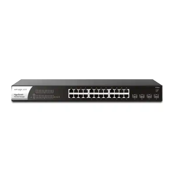
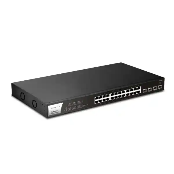
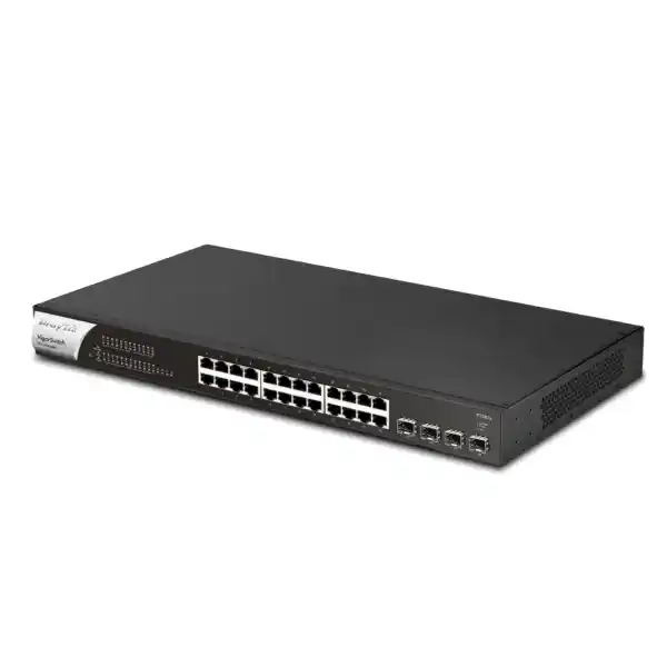
DrayTek VigorSwitch P1281x in UAE
A practical access-layer PoE+ switch for offices, surveillance networks, wireless deployments, VoIP environments and distributed business sites that require twenty-four Gigabit powered access ports together with four high-speed 1G/10G SFP+ uplinks. The VigorSwitch P1281x combines a 140W PoE budget, 56Gbps switching capacity, VLAN segmentation, QoS, link aggregation, surveillance-aware management and DrayTek centralized administration in a compact 1U rack-mount platform.
All 24 RJ-45 access ports support IEEE 802.3af/at powered devices, simplifying cabling for IP cameras, wireless access points and desk phones.
Four SFP+ interfaces support 1G/10G optical or compatible direct-attach uplinks for aggregation, core connectivity and resilient multi-link designs.
A browser-based interface provides VLAN, QoS, link aggregation, surveillance, security and monitoring controls without requiring a command-line-centric workflow.
ONVIF discovery, surveillance topology, camera maintenance functions and device checks help administrators operate camera networks from the switching layer.
What the DrayTek VigorSwitch P1281x is designed to do
The DrayTek VigorSwitch P1281x is positioned as a Web Smart managed PoE+ switch for networks that need more operational control than an unmanaged switch but do not require the full routing and advanced Layer 3 feature set of a higher-tier enterprise access switch. Its hardware arrangement is straightforward: twenty-four Gigabit Ethernet copper access interfaces provide data and PoE/PoE+ delivery, while four SFP+ interfaces provide 1Gbps or 10Gbps fiber-capable uplink connectivity. This makes the switch well suited to an access-layer role where many endpoint devices need to converge into a smaller number of fast links toward a core switch, aggregation switch, firewall, server network or another building distribution point.
For a typical UAE office, retail site, warehouse, school, clinic, small hotel, CCTV deployment or branch network, the P1281x can sit in a communications cabinet and serve powered endpoints across structured copper cabling. Instead of installing separate mains adapters beside each IP camera or access point, the switch can deliver power through the same Ethernet cable used for data. That reduces local power requirements at endpoint positions and gives administrators the ability to manage PoE behavior centrally. The 140W total PoE budget must be planned correctly, but for environments with moderate-power endpoints it can support a useful mix of cameras, phones and access points.
The four SFP+ ports are particularly important because they provide headroom between the edge and the rest of the network. A 24-port access switch can accumulate significant traffic even when no single endpoint exceeds 1Gbps. Multiple 10G uplink options allow designers to separate traffic paths, build link aggregation groups, connect to redundant upstream devices where the topology permits, or dedicate uplinks for camera recording, office LAN traffic and server access. The switch therefore addresses a common practical requirement: keep endpoint connectivity cost-efficient at 1Gbps while avoiding a 1Gbps bottleneck between the access layer and the aggregation layer.
Organizations comparing switch options through FourTeck UAE can use the P1281x when the required feature profile is primarily managed Layer 2 switching, PoE+, VLAN separation, QoS, link aggregation, device monitoring and surveillance integration. For broader security architecture and firewall projects, the switch can be integrated into a segmented LAN behind security appliances and managed as one component of a larger network design through Firewall Dubai.
Technical specification overview
Port architecture and traffic design
Ports 1 through 24 form the copper access layer. Each port can negotiate standard Ethernet rates up to 1Gbps and can provide PoE to a compatible powered device. From a network-design perspective, these interfaces are where user endpoints and infrastructure endpoints attach: IP phones, printers, access points, cameras, network controllers, workstations, building-management devices and other Ethernet-connected systems. The switch can then classify, segment and prioritize traffic before forwarding it toward other endpoints or upstream links.
Ports 25 through 28 are the SFP+ interfaces. The value of four uplinks is not simply that they run faster. Four discrete interfaces give the designer several topology choices. One organization may use a single 10G uplink to a core switch and keep the remaining ports for expansion. Another may place two 10G interfaces in an LACP bundle, use one 10G link to a video-recording network and reserve another for a secondary cabinet. A multi-building site may use fiber transceivers to extend network connectivity beyond copper distance constraints. A data-room deployment may use short direct-attach cables to an aggregation switch where compatible optics and cabling are selected.
The P1281x supports static aggregation and LACP. Link aggregation can increase aggregate bandwidth across compatible links and can also provide path resilience when designed correctly with compatible upstream equipment. It is important to understand that an individual Ethernet flow is normally hashed to one member link rather than striped at packet level across every link. Consequently, combining two 10G links can raise the total capacity available to many simultaneous flows, but it does not automatically make one single flow operate at 20Gbps. This distinction matters when the switch is carrying many IP camera streams, dozens of office sessions or multiple access points because aggregate throughput is usually the more relevant metric.
The 56Gbps switching-capacity specification and 41.7Mpps forwarding-rate figure characterize the platform’s switching performance under vendor-stated test conditions. In practical designs, performance also depends on frame sizes, traffic distribution, enabled functions, uplink design, oversubscription, endpoint behavior and upstream bottlenecks. A switch is only one stage in the path. For example, a 10G uplink into a firewall does not create 10Gbps Internet throughput if the firewall, ISP circuit, security inspection profile or remote endpoint operates at a lower rate. Similarly, a 1Gbps camera-recording server NIC can become a constraint even if the switch fabric and uplink have additional capacity.
For structured deployments, treat the P1281x as an access switch and size upstream links according to measured or estimated traffic. Office endpoints often generate bursty traffic with low sustained utilization, whereas surveillance endpoints generate relatively steady streams. Wireless access points can exhibit both patterns depending on client density. Mixing these traffic classes is entirely practical, but VLAN separation, QoS and uplink planning should be deliberate rather than left to default settings.
PoE design: how to size the 140W budget correctly
The VigorSwitch P1281x supports IEEE 802.3af and IEEE 802.3at powered devices across its twenty-four RJ-45 ports. IEEE 802.3af is commonly associated with lower-power devices, while 802.3at PoE+ provides a higher per-port power class for devices that require more energy. The important system-level limit on this model is the 140W total PoE budget. That value must cover the combined allocation or consumption of all powered devices connected at the same time.
A simple sizing method is to list every powered endpoint, note its maximum expected PoE draw, add the values, and include sensible engineering headroom. Suppose a branch site has eight cameras rated for a maximum 9W each, four phones rated for 6W each and three wireless access points rated for 15W each. The theoretical maximum is 72W for cameras, 24W for phones and 45W for access points, for a combined 141W. That is already beyond the 140W switch budget, even though many endpoints may use less power during normal operation. This configuration should therefore be redesigned rather than accepted on the assumption that all devices will remain below their maximum draw.
A more conservative design might place twelve 7W cameras and four 8W phones on the switch. That totals 116W, leaving 24W of nominal budget. Whether that margin is sufficient depends on the actual device specifications, startup behavior, environmental conditions and future expansion. Wireless access points with multiple radios can draw significantly more than simple phones, especially under high load or when powering USB accessories. Pan-tilt-zoom cameras, IR illuminators and heaters can also increase consumption compared with fixed indoor cameras. Always use the powered-device data sheet rather than a generic category assumption.
PoE scheduling can reduce unnecessary power use or enforce operational policies. In some environments, selected access points or phones may be powered only during defined hours. In other cases, surveillance cameras should remain powered continuously and should never be scheduled off. The switch also supports device-check behavior that can ping a monitored endpoint and, when configured, cycle PoE if the endpoint stops responding. This can help recover certain hung devices without dispatching an engineer merely to disconnect and reconnect a cable. It should be used carefully: a failed ping does not always mean that power cycling is the correct response, particularly if the device is intentionally blocking ICMP or the network path rather than the endpoint itself has failed.
For UAE projects, PoE planning should be included in the quotation stage together with endpoint quantities, exact models, cable distances, rack ventilation, UPS sizing and expected growth. A 24-port switch is not automatically a 24-device PoE solution if the connected devices collectively require more than 140W. When a design requires many high-power devices, consider splitting the load across multiple switches or choosing a higher-budget PoE platform.
VLAN segmentation for business, voice, wireless and surveillance traffic
VLANs are one of the central reasons to use a managed switch rather than an unmanaged model. The P1281x supports up to 512 VLANs and includes 802.1Q tag-based VLANs along with management, voice, surveillance, MAC-based and protocol-based VLAN functions. In a well-designed network, VLANs create logical separation between device classes even when those devices connect to the same physical switch. For example, office computers can reside in one VLAN, IP phones in another, CCTV cameras in another, guest wireless clients in another and switch-management interfaces in a restricted infrastructure VLAN.
The switch itself is primarily a Layer 2 platform and does not provide the static routing and VLAN routing functions of DrayTek’s L2+ models. Inter-VLAN communication therefore belongs on an upstream Layer 3 device such as a firewall, router or core switch. This architecture is often desirable because it centralizes security policy at a device designed to enforce it. A camera VLAN can be allowed to reach an NVR while being denied access to finance workstations. A guest VLAN can be permitted to reach the Internet but blocked from internal servers. A voice VLAN can receive differentiated QoS handling and tightly defined access to call-control services.
Trunk links carry multiple tagged VLANs between the P1281x and an upstream switch, router or firewall. Access ports generally carry the untagged traffic of one endpoint VLAN, though voice deployments can use mechanisms such as LLDP-MED and voice VLAN features to separate phone traffic from an attached workstation where the phone provides a downstream PC port. The precise configuration should reflect the phone vendor, DHCP options, LLDP behavior and call-platform design.
Management VLAN separation deserves special attention. Leaving infrastructure management interfaces accessible from the same network as ordinary user devices expands the attack surface. A more disciplined deployment places switch management on a dedicated VLAN that is reachable only from approved administrator workstations, jump hosts or network-management systems. Access-control policies on the upstream firewall can then limit HTTPS, SSH, SNMP and other management traffic to authorized sources.
VLANs are not a complete security system by themselves. Their value depends on correct port membership, trunk configuration, upstream routing rules and administrator discipline. When deployed as part of a broader security architecture, however, they are an effective foundation for reducing broadcast scope, separating trust zones and making policies easier to understand and audit.
QoS and traffic priority
Eight QoS queues, strict-priority and weighted round-robin scheduling, CoS, DSCP and IP Precedence handling allow important traffic to receive differentiated treatment. This is useful for voice, interactive applications and selected business-critical flows when congestion occurs.
Rate limiting
Per-port or policy-based rate controls can prevent a device class from consuming disproportionate bandwidth. Rate limiting should be applied with an understanding of application behavior so that legitimate bursts, backups or software distribution are not unintentionally constrained.
Loop protection
STP, RSTP and loop-protection functions help prevent Layer 2 loops from creating broadcast storms or destabilizing the LAN. Redundant links should be engineered deliberately rather than connected casually between switches.
Energy efficiency
IEEE 802.3az Energy Efficient Ethernet support can reduce interface power consumption when traffic conditions allow. Actual savings depend on link state, connected equipment and workload.
ONVIF surveillance features and CCTV operations
One of the distinguishing characteristics of the VigorSwitch P1281x is its ONVIF-oriented surveillance functionality. ONVIF is widely used in IP video environments to improve interoperability between surveillance devices and management systems. The switch can discover compatible ONVIF devices, present a surveillance topology and provide access to selected device-maintenance functions. This helps network administrators understand which cameras are attached to which switch ports and can shorten troubleshooting when a camera goes offline.
Traditional switch troubleshooting begins at the port level: is the link up, what speed was negotiated, is PoE being delivered, is traffic moving and which VLAN is assigned? Surveillance-aware management adds device context. Instead of seeing only an anonymous MAC address, the administrator may be able to identify a camera through ONVIF discovery and inspect the surveillance topology. This is useful in buildings where dozens of cameras are distributed across floors, entrances, parking areas, corridors and service spaces.
The switch also supports monitoring behaviors associated with camera availability and snapshots. In practical operations, such tools can help an administrator identify that a camera has become unreachable and then decide whether to attempt a PoE restart. Automated recovery can reduce downtime caused by transient endpoint faults, but it should not be viewed as a substitute for root-cause analysis. Repeated camera resets may indicate cabling faults, marginal power, firmware problems, overloaded endpoints, address conflicts or network-policy issues that require proper investigation.
For video networks, bandwidth sizing should account for codec, resolution, frame rate, scene complexity and recording mode. A 4MP H.265 camera may have a very different bit rate from a 4K camera using high frame rates and less efficient settings. Multiply the expected bit rate by camera count, include overhead and design margin, and verify that the uplinks and NVR interfaces are sized accordingly. Twenty-four cameras at 8Mbps each generate roughly 192Mbps of payload traffic before overhead, which is easily within a Gigabit link in many cases. Higher-resolution cameras, multiple client streams, analytics traffic, camera management and server backup traffic can increase this substantially.
VLAN separation is strongly recommended for surveillance networks. Cameras generally do not need unrestricted access to user workstations or business servers. Place them in a dedicated VLAN, route through an upstream firewall or Layer 3 device, and explicitly allow only the services they require. The NVR, VMS server, time server, DNS services and authorized administration stations can then be permitted according to policy. This reduces exposure and creates clearer operational boundaries.
For CCTV projects that also require server, storage or NVR infrastructure planning, organizations can coordinate switching with broader compute requirements through Server Dubai. Treat recording retention, RAID/storage sizing, camera bit rates, uplink bandwidth and PoE capacity as one integrated design exercise rather than independent purchasing decisions.
Security and network-stability controls
The P1281x includes several controls that help maintain a stable Layer 2 environment. IP Conflict Detection and Prevention can identify duplicate or problematic IP use and can be configured to block offending hosts in supported scenarios. Duplicate IP addresses are a common source of intermittent connectivity problems because two devices may respond for the same address, causing ARP tables to change unpredictably. In an office or surveillance network with statically configured devices, conflict detection can materially reduce troubleshooting time.
Traffic-control capabilities include storm control and denial-of-service defense features at the switching layer. Storm control is useful for limiting excessive broadcast, multicast or unknown traffic that might otherwise consume large portions of the LAN. It does not replace firewall-based threat prevention, but it can help contain Layer 2 abnormal behavior before it affects every connected endpoint.
The switch supports access-control capabilities, SNMP v1/v2c/v3, secure web access through HTTPS and SSH v2 for management. Administrators should favor encrypted management protocols and SNMPv3 where operationally practical. Legacy management services should be disabled when they are not required, and management access should be restricted by network policy. Strong credentials, configuration backups, controlled firmware maintenance and limited administrator access remain essential even on an internal switch.
The platform does not provide the more advanced security controls found on higher-tier DrayTek managed switches, such as DHCP Snooping, Dynamic ARP Inspection and IP Source Guard according to the published feature matrix. If those capabilities are mandatory for the access layer, a different model should be selected. This distinction is important in procurement: selecting a switch should begin with required controls and topology, not merely port count.
Management options: local GUI, VigorRouter, VigorConnect and VigorACS
Local management is available through a browser-based interface, which is appropriate for individual sites where administrators want direct visibility into port state, PoE delivery, VLAN configuration, link aggregation, QoS and other switch functions. For many small and medium organizations, this approach is easier to operate than a command-line-only switch because common tasks can be performed through structured screens and status views.
In environments that use compatible DrayTek routers, Switch Management features can provide discovery, provisioning, monitoring and a hierarchical view from the router. This can simplify branch administration when a router and one or more DrayTek switches are deployed together. VLAN and port-control profiles can be centrally coordinated, and common maintenance tasks can be performed without opening a separate browser session to every switch.
VigorConnect is another management option intended for DrayTek AP and switch environments. It supports device discovery, provisioning, monitoring, alarms and maintenance workflows. VigorACS extends centralized management further and is designed for larger or distributed deployments where multiple DrayTek routers, access points and switches need coordinated monitoring and remote management. For managed-service providers or businesses with several branches, centralized management can reduce the cost of routine changes because an administrator does not need to travel to every site for basic configuration.
Centralization does not remove the need for good operational practice. Administrators should maintain a standard naming convention, document switch locations and uplink paths, export configuration backups after significant changes, define maintenance windows and track firmware versions. A central platform is most valuable when the underlying network inventory is accurate and the organization knows which switch, port, endpoint and VLAN correspond to each business function.
For organizations that want deployment, migration, monitoring and network-management assistance beyond the hardware itself, FourTeck IT Services UAE can be used as a reference point for broader implementation requirements. Switch procurement should be coordinated with configuration, testing, documentation and handover requirements rather than treated as a stand-alone box purchase.
Deployment scenarios
Business office
Use separate VLANs for staff, voice, printers, guest Wi-Fi and management. Power IP phones and access points from selected PoE ports, reserve SFP+ uplinks for the distribution layer, and apply QoS to voice and interactive applications.
IP surveillance network
Connect up to twenty-four camera or mixed endpoints within the 140W budget, place cameras in a surveillance VLAN, use ONVIF visibility for operations, and uplink at 10G where recording or analytics traffic justifies the additional capacity.
Wireless access layer
Power multiple Wi-Fi access points while transporting tagged SSIDs across VLAN trunks. Confirm each AP’s maximum PoE requirement and ensure that 1Gbps access ports are suitable for the selected APs’ wired uplink capability.
Retail or hospitality branch
Separate point-of-sale, staff, voice, cameras, signage and guest networks. Centralized management can simplify remote support when the switch is installed in a branch communications rack.
Education or training facility
Segment administration, student, lab, voice and camera systems. Use fiber uplinks to connect floors or separate wiring closets while maintaining centrally defined VLAN policies.
Warehouse or light industrial site
Support cameras, phones, access points and networked devices from a protected communications room. Verify ambient temperature, dust control, cabinet ventilation and cable-path design because the P1281x is a commercial rack switch rather than an industrial hardened switch.
How to design uplinks and prevent bottlenecks
A 10G uplink is most valuable when the downstream access switch carries enough traffic to justify it or when future growth is expected. In many ordinary offices, twenty-four Gigabit endpoints rarely transmit at line rate simultaneously, so a single 10G uplink provides substantial aggregate capacity. For CCTV deployments, traffic is more predictable because cameras stream continuously. Add the expected bit rates, include overhead, and consider whether live viewing, recording, analytics and backup processes will traverse the same uplink.
When two or more SFP+ links are aggregated, both sides must be configured compatibly. LACP parameters, allowed VLANs, native VLAN behavior and link speed must match the upstream device. A mismatch can lead to partial connectivity, loops or unexpected path selection. It is good practice to label both ends of every fiber or DAC link and document the exact switch ports used in the bundle.
Fiber selection should be based on distance and existing plant. Short-range multimode optics may be appropriate inside a building or campus where compatible multimode fiber is installed. Single-mode optics can support much longer runs. Direct-attach copper can be efficient for short connections inside the same rack or adjacent racks. Transceiver compatibility, optical budget and connector type should be verified before ordering. The presence of an SFP+ cage does not mean that every third-party module will necessarily provide the same support experience.
Resilience requires more than multiple cables. If two uplinks terminate on the same upstream switch, an upstream hardware failure still interrupts service. Higher availability may require dual upstream switches and a topology designed around their capabilities. Because the P1281x supports STP/RSTP rather than MSTP and is not a stackable switch, designers should choose a redundancy approach that is simple, deterministic and compatible with the upstream infrastructure.
Avoid overengineering small sites. A clear single-uplink topology with documented spare ports may be more reliable than unnecessary redundancy configured by staff who do not maintain it. The right design balances availability requirements, operational skill, budget and the business cost of downtime.
QoS planning for IP telephony and real-time applications
Voice and interactive media traffic can be sensitive to delay, jitter and packet loss. The P1281x provides multiple QoS mechanisms, including eight queues and classification using CoS, DSCP and IP Precedence. In a properly designed voice network, endpoints or upstream systems mark real-time traffic, and the switch uses those markings to place packets into appropriate queues. Weighted or strict-priority scheduling can then protect latency-sensitive traffic during congestion.
QoS should not be treated as a substitute for sufficient bandwidth. If an uplink is continuously saturated, QoS determines which traffic suffers rather than creating additional capacity. The goal is to provide enough bandwidth for normal operation and use QoS to handle bursts, contention and priority differences. For example, a large software deployment or backup should not cause voice calls to become unusable if the network has been designed and classified properly.
Voice VLAN features can simplify phone deployment by logically separating telephony from workstation traffic. LLDP-MED can help communicate network policies to compatible endpoints. In mixed environments where different phone vendors or older devices are used, test auto-discovery behavior before deploying it site-wide. Explicit configuration may be preferable when predictability is more important than automation.
For deployments that include IP PBX infrastructure, desk phones or SIP platforms, the switch can form the PoE access layer while voice services are delivered elsewhere in the network. Coordination between switching, firewall, SIP, DHCP, VLAN and QoS settings is essential to avoid one-way audio, registration failures or inconsistent phone provisioning.
Important platform limitations to consider before purchase
The VigorSwitch P1281x is a Web Smart Layer 2 switch rather than a full Layer 3 or L2+ routing switch. It does not provide static routing, VLAN routing or a DHCP server according to the published feature set. If the network architecture requires routing directly on the access switch, select a different platform and confirm the exact Layer 3 feature scope before purchase.
The switch supports PoE and PoE+, not 802.3bt PoE++. Devices that require PoE++ should not be planned on this model. Similarly, the 140W total PoE budget is significantly lower than the aggregate theoretical maximum of twenty-four 30W PoE+ ports, so endpoint power must be calculated as a system rather than judged from the per-port capability.
The copper access interfaces are Gigabit Ethernet rather than 2.5GbE or 5GbE multigigabit ports. This is suitable for many phones, cameras, computers and conventional access points, but high-performance Wi-Fi access points with 2.5GbE uplinks may be constrained to 1Gbps when connected to this switch. If multigigabit access is a requirement, choose a model designed for that purpose.
There is no hardware stacking feature in the published specification. Multiple P1281x switches can operate in the same network and can be centrally managed, but they do not become one hardware stack with a shared control plane. Designs requiring stacking, advanced redundancy, DHCP Snooping, Dynamic ARP Inspection, IP Source Guard, MSTP or Layer 3 routing should be matched to a higher-tier switch platform.
UAE deployment considerations: rack, cooling, cabling and power
The P1281x is a 1U rack-mount switch measuring approximately 440 x 216 x 44mm and weighing around 3.25kg. It should be installed in a proper 19-inch cabinet or rack with adequate front and rear clearance, structured cable management and ventilation. Even though its depth is modest, space planning should include patch panels, horizontal cable managers, fiber trays, PDUs, UPS equipment and bend radius for optical patch cords.
The published operating range is 0 to 50°C, with non-condensing humidity limits. In the UAE, this makes environmental control especially important. Network closets exposed to direct sun, poor ventilation or intermittent air conditioning can exceed comfortable operating conditions even when the occupied office area remains cool. Temperature inside a closed wall cabinet can be substantially higher than the room itself. The switch should therefore be installed in a conditioned or adequately ventilated technical space rather than an unprotected outdoor enclosure.
Power input is 100–240V AC, which suits typical UAE mains environments when the supplied or locally appropriate power cord is used. Business-critical installations should normally connect the switch to a UPS because loss of switch power also removes PoE power from connected cameras, phones and access points. UPS sizing must include the switch’s own load plus the downstream PoE load and desired runtime. A 140W PoE budget does not mean the switch consumes exactly 140W; overall system consumption varies with endpoint load, switch operation and efficiency, and the published maximum consumption is higher.
Copper cabling should meet the required category and installation standard. Cat 5e can support Gigabit Ethernet at standard channel distances when properly installed, though many new commercial projects standardize on Cat 6 or better. PoE adds thermal considerations in large cable bundles, especially at higher power levels. Certified cabling, proper termination and testing are important because marginal pairs can create intermittent Ethernet or PoE faults that appear to be switch problems.
Fiber uplinks should be planned with the correct transceiver type and fiber grade. Before procurement, record the distance, connector type, existing fiber mode, patch-panel presentation and target upstream switch. This prevents the common situation where the switch arrives but the correct optics or patch cords are missing from the bill of materials.
Installation and commissioning methodology
A professional switch deployment should begin before the device is installed. Create a port plan that maps each physical port to its intended endpoint, VLAN, PoE state, description and expected link speed. Reserve uplink ports and document which SFP+ interface connects to which upstream port. If link aggregation will be used, define both sides of the bundle in advance.
After rack installation and power-up, establish management access from an isolated commissioning network or approved management VLAN. Change default credentials immediately and configure the intended management IP, subnet mask, gateway and DNS/NTP settings as appropriate. Use HTTPS and SSH rather than insecure management protocols where possible. Restrict administrator access to known management sources.
Create VLANs and assign port membership according to the approved network design. Configure trunks to carry only the VLANs required at each uplink. Avoid allowing every VLAN everywhere simply because it is convenient. Constraining VLAN propagation reduces accidental exposure and makes troubleshooting easier. For voice and surveillance deployments, validate auto-VLAN behavior in a test port before enabling it broadly.
Configure PoE policy after endpoint requirements are known. Label ports that must remain powered continuously, identify scheduled ports and define any device-check behavior carefully. Connect powered devices in stages while monitoring total PoE consumption so that a mistaken power assumption is discovered during commissioning rather than after handover.
QoS should be tested under load. Generate representative traffic while placing voice calls, streaming cameras or running the applications that matter to the business. Confirm that priority behavior is functioning and that uplinks are not consistently saturated. Do not rely solely on configuration screenshots; test real traffic paths.
Finally, export a configuration backup and document the installed firmware version, management address, administrator process, port map, VLAN table, uplink topology, transceiver types and connected critical endpoints. A concise handover document can save hours during a future incident. Good documentation is part of the network design, not an optional administrative task.
If the switch is part of a larger infrastructure refresh, align commissioning with firewall rules, DHCP scopes, wireless SSIDs, IP PBX settings, camera addressing, NVR storage and monitoring. A switch can be configured perfectly and still appear to fail if the upstream network has not been prepared for the new VLANs and routes.
Operational monitoring and troubleshooting
Start troubleshooting at the physical layer. Check whether the port is up, verify negotiated speed, inspect patching and confirm that the endpoint receives PoE if required. A powered device can sometimes light up while data connectivity remains faulty because PoE and Ethernet use the cable in related but distinct ways. Cable testing and port substitution can quickly isolate physical issues.
Next, verify VLAN membership. Many apparent switching failures are actually tagging mismatches: an access port is assigned to the wrong VLAN, a trunk does not allow the required VLAN, or the upstream firewall lacks the corresponding subinterface. Confirm the endpoint’s IP address, gateway and DHCP lease, then trace the VLAN path from edge port to uplink.
For camera networks, ONVIF topology and device-check features add operational context. If one camera fails, compare its port state and PoE draw to neighboring cameras. If many cameras fail simultaneously, investigate the common uplink, VLAN, NVR or power source rather than power-cycling every endpoint individually. Patterns are diagnostically valuable.
SNMP can feed status data into a network-monitoring platform. Useful metrics include port state, traffic counters, error rates, device availability and environmental or power information exposed by the switch. Set thresholds that indicate actual problems rather than creating constant low-value alerts. Monitoring should answer operational questions: which link is congested, which endpoint is flapping, which uplink has errors and when did the change begin?
When making firmware changes, follow a controlled process. Review release notes, back up configuration, schedule a maintenance window and confirm recovery access. Do not interrupt power while the switch is writing configuration or firmware. After an upgrade, verify uplinks, VLANs, PoE operation and management connectivity before closing the change.
P1281x compared with common alternative requirements
The correct question is not whether the P1281x is universally better than another switch; it is whether its capabilities match the project’s requirements. If the design needs twenty-four Gigabit PoE+ access ports, a moderate 140W power budget, four 10G-capable fiber uplinks, VLANs, QoS and practical centralized management, the P1281x aligns well with that profile. If the project needs 2.5GbE access, PoE++, a 400W or higher PoE budget, advanced Layer 3 routing, stacking or high-end access security features, a different switch category is more appropriate.
Compared with an unmanaged 24-port PoE switch, the P1281x provides much greater control over VLANs, QoS, topology, monitoring and PoE operations. The additional management layer becomes valuable as soon as the network carries multiple business services or needs remote troubleshooting. Unmanaged switches are simple, but they cannot provide the same segmentation or visibility.
Compared with a full L2+ enterprise switch, the P1281x is simpler and omits certain advanced capabilities. That can be an advantage in a branch where routing belongs on the firewall and operators want a straightforward managed access switch. It can be a limitation in a campus core or distribution role where routing, advanced security and high availability features are mandatory.
Procurement should therefore start with a matrix: required port count, endpoint speeds, PoE standards, total PoE wattage, uplink quantity, uplink speed, VLAN scale, routing requirements, access security, redundancy, management platform and environmental limits. Map the switch against those requirements and reject it if any non-negotiable item is missing.
Detailed use case: mixed office, Wi-Fi, voice and CCTV
Consider a two-floor office that needs twelve IP cameras, six IP phones, four wireless access points and several non-PoE devices. A P1281x can serve as an access switch if the total PoE demand remains within 140W. Cameras may be connected on ports 1–12, phones on 13–18, access points on 19–22 and two ports reserved for local non-PoE devices or growth. The four SFP+ interfaces provide uplink flexibility.
The logical design might use VLAN 10 for corporate users, VLAN 20 for voice, VLAN 30 for cameras, VLAN 40 for guest Wi-Fi and VLAN 99 for management. Access points carry tagged corporate and guest SSIDs while using a management VLAN for their own administrative traffic. Phones use the voice VLAN and may pass workstation traffic through a separate data VLAN. Cameras remain isolated in VLAN 30 and are permitted to communicate only with the NVR, DNS/NTP services and authorized maintenance systems.
One 10G SFP+ uplink can carry the VLAN trunk to the main core or firewall. If the NVR is located elsewhere and camera traffic is heavy, another SFP+ interface can connect to a dedicated aggregation path depending on the architecture. LACP could be used for aggregate capacity where both devices support a compatible configuration. The remaining SFP+ ports can be retained for expansion or a secondary cabinet.
QoS marks voice as high priority, while guest traffic can be rate-limited to protect business services. The switch’s ONVIF functions help map cameras to ports. Device checks can monitor selected cameras or access points and issue alerts when they become unreachable. Configuration backup is stored after commissioning.
The PoE calculation remains decisive. If each camera can draw 7W, the twelve cameras account for 84W. If phones draw 5W each, six phones add 30W, bringing the total to 114W. Four access points drawing 12W each would add 48W, raising the requirement to 162W, which exceeds the switch’s 140W budget. The solution might be to power some access points from another switch or injector, reduce powered endpoint count, or choose a switch with a larger PoE budget. This example demonstrates why port availability alone is not enough for PoE sizing.
If the access points actually require 2.5GbE Ethernet, the P1281x also becomes a speed constraint because its copper access ports are Gigabit. A requirements review may therefore lead to a multigigabit PoE switch instead. Good design is not about forcing a selected model into the project; it is about matching the platform to the workload.
Detailed use case: dedicated surveillance cabinet
A dedicated surveillance cabinet is one of the clearest use cases for the P1281x because the device combines PoE+ access with 10G uplinks and ONVIF-oriented operations. Imagine eighteen fixed cameras distributed through a commercial property. Each camera uses an average of 5W with a specified maximum of 8W. At the maximum figure, eighteen cameras require 144W and would exceed the 140W budget, so the project must be adjusted. At seventeen cameras the theoretical maximum becomes 136W, leaving only 4W headroom, which may still be too tight for a robust design. A lower camera count or higher-budget switch may be preferred.
From the bandwidth side, suppose each camera averages 6Mbps. Eighteen cameras generate about 108Mbps before overhead, well within a Gigabit path. However, if multiple viewing clients pull secondary or primary streams, analytics servers request additional feeds, or cameras use much higher bit rates, traffic rises. A 10G uplink is therefore not always required for raw recording bandwidth but can provide useful headroom and allow the surveillance switch to integrate into a higher-speed core without becoming the bottleneck.
The surveillance VLAN should terminate on a firewall or Layer 3 switch with rules limiting outbound and lateral access. Cameras rarely need unrestricted Internet access. Firmware-update workflows, cloud connectivity and remote viewing requirements should be explicitly documented. If remote viewing is provided through an NVR or VMS platform, expose the minimum necessary services rather than publishing cameras directly to the Internet.
ONVIF discovery can help map the camera estate, but the authoritative asset register should still include camera name, location, IP address, MAC address, switch port, VLAN and recording server. Physical labels in the cabinet should correspond to the logical names used by the VMS. When a security team reports that “Loading Bay Camera 3” is offline, the network team should be able to identify the exact switch and port without tracing cables manually.
UPS runtime is especially important for surveillance. If the property expects cameras to continue during short power interruptions, size the UPS for the switch plus the actual PoE load and the NVR or related equipment that must remain active. A camera network powered by PoE will fail as a group when the switch loses power, so the switch becomes part of the surveillance power architecture, not merely the data path.
Detailed use case: multi-site branch standardization
Organizations with multiple branches often benefit from standardizing on a small number of switch templates. A 24-port PoE+ model such as the P1281x can fit branches that need a combination of phones, access points, cameras and local devices. Standardization simplifies spare inventory, administrator training and configuration templates. It also makes documentation more consistent because port conventions and VLAN IDs can be reused across locations.
A branch template might reserve ports 1–8 for phones, 9–12 for wireless access points, 13–20 for cameras, 21–24 for local infrastructure, SFP+ 25–26 for primary uplinks and SFP+ 27–28 for growth or special connections. Real sites will differ, but a consistent starting pattern reduces configuration errors. Port descriptions should identify the physical room or endpoint, not just the device type.
Central management through compatible DrayTek systems can reduce travel. An administrator can monitor whether a branch switch is online, review alerts and perform selected maintenance remotely. Before adopting any central management method, the organization should define who can make changes, how credentials are protected, where configuration backups are stored and how changes are approved.
Branch standardization also makes lifecycle planning easier. If a future wireless upgrade requires 2.5GbE access ports, the organization can identify which branch switches no longer meet the standard and replace them systematically. The P1281x then remains useful in sites where Gigabit access is sufficient rather than being treated as a one-size-fits-all platform.
Procurement checklist for UAE buyers
Before requesting a final quotation, confirm the following technical inputs. The goal is to ensure that the quoted switch, optics, accessories and deployment services match the real project rather than only the model name.
- Total number of copper endpoints required now and expected within the planning horizon.
- Which endpoints require PoE, their exact models and maximum power consumption.
- Whether any endpoint requires PoE++ rather than PoE/PoE+.
- Whether any access device requires more than 1Gbps over copper.
- Required SFP+ uplink count, speed, distance and fiber type.
- Whether link aggregation or redundant paths are required.
- VLAN design and the location of the Layer 3 gateway or firewall.
- Required access-layer security features and whether the P1281x feature set is sufficient.
- Rack size, power availability, UPS requirement and cabinet cooling.
- Need for installation, configuration, testing, documentation and ongoing support.
Frequently asked technical questions
Does the P1281x provide 24 PoE+ ports?
Yes. All twenty-four Gigabit RJ-45 access ports support IEEE 802.3af/at PoE/PoE+. The total power available across those ports is limited to the switch’s 140W PoE budget.
Can every port deliver 30W at the same time?
No. Although individual ports support PoE+, the total 140W budget prevents twenty-four ports from each delivering the maximum PoE+ power simultaneously. Size the connected devices as a combined load.
Are the SFP+ ports 10G capable?
Yes. The four uplink interfaces support 1G/10G SFP+ connectivity, subject to compatible transceivers, cabling and the connected device.
Does it support Layer 3 routing?
No. The published feature matrix does not list static routing or VLAN routing for this model. Use an upstream router, firewall or Layer 3 switch for inter-VLAN routing.
Can it be used for CCTV?
Yes. The switch includes ONVIF-oriented surveillance features, PoE+, surveillance VLAN capability and device monitoring. Confirm total camera power and bandwidth before deployment.
Can it power Wi-Fi 6 or Wi-Fi 7 access points?
It can power compatible 802.3af/at devices within the 140W budget, but its access ports are limited to 1Gbps. APs that require 2.5GbE or PoE++ may need a different switch.
Does it support LACP?
Yes. Static aggregation and IEEE 802.3ad LACP are supported, with up to eight aggregation groups and up to eight members per group according to the published specification.
Is it rack mountable?
Yes. It uses a 1U rack-mount form factor and is supplied with rack-mount hardware as part of the normal package contents.
Decision recap: when the VigorSwitch P1281x fits the project
Strong fit when
You need up to 24 Gigabit PoE/PoE+ access ports, can stay within a 140W PoE budget, want four 10G-capable SFP+ uplinks, require VLANs and QoS, value ONVIF surveillance functions, and plan to perform Layer 3 routing elsewhere in the network.
Consider another model when
You require PoE++, substantially more than 140W of PoE, 2.5GbE access ports, switch-based routing, advanced DHCP Snooping/DAI/IP Source Guard controls, hardware stacking, MSTP or other higher-tier campus features.
Quotation input checklist
For a precise UAE quotation, prepare the following information so the switch and accessories can be sized without assumptions:
Number of cameras, phones, access points and non-PoE devices.
Exact maximum wattage for every powered-device model.
1G or 10G, fiber distance, connector and transceiver requirement.
VLANs, firewall/core model, routing location and redundancy goals.
Cabinet space, UPS runtime target, room cooling and power distribution.
Installation, configuration, testing, documentation, migration or support scope.
Plan the DrayTek VigorSwitch P1281x as part of the complete LAN
A reliable switch deployment depends on more than ordering the correct chassis. Port count, PoE power, VLAN design, fiber uplinks, firewall rules, UPS runtime, rack cooling and endpoint requirements should be reviewed together. The DrayTek VigorSwitch P1281x is best used where its strengths—24 Gigabit PoE+ ports, four 10G SFP+ uplinks, 140W PoE budget, Web Smart management and surveillance-aware tools—align directly with the site requirements.
For UAE projects, FourTeck can structure the bill of materials around the switch, compatible uplink optics, patching, rack integration and the surrounding network architecture. Where the project extends across multiple regions or requires broader vendor coordination, the FourTeck global site provides an additional reference for infrastructure sourcing and technical engagement.
Before purchase, confirm the exact endpoint inventory and power profile. This avoids oversizing some parts of the network while discovering too late that the PoE budget, access speed or routing feature set is insufficient. A short design review at quotation stage is usually faster and less expensive than correcting a mismatch after installation.

Reviews
There are no reviews yet.