
High-density 100GbE data center switching for Dubai and the UAE
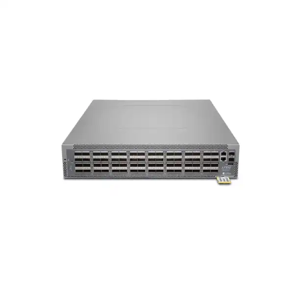
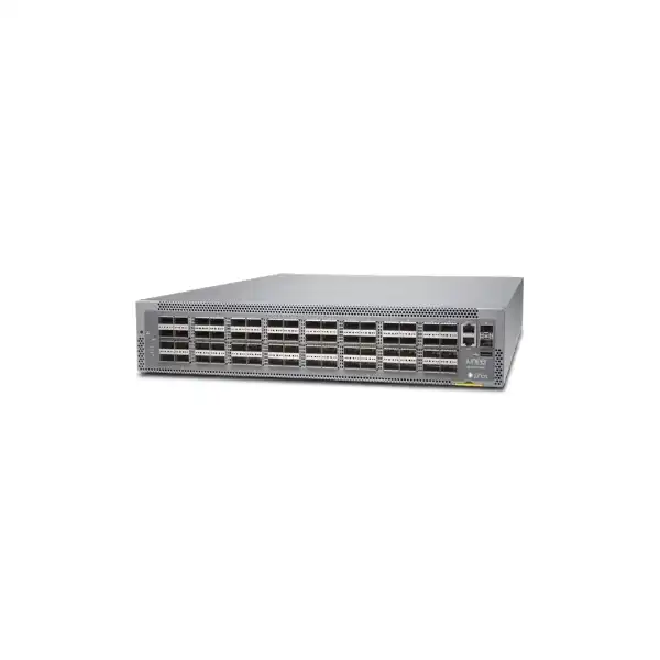
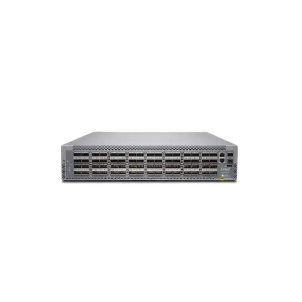
Juniper QFX5210 Data Center Switch
The QFX5210 is a 2U fixed-configuration switch designed for high-density spine-and-leaf networks, server aggregation and IP fabrics that need 10GbE, 25GbE, 40GbE and 100GbE connectivity. Its value comes from 64 QSFP+/QSFP28 ports, line-rate forwarding, Junos OS operations and a hardware design that suits large east-west traffic environments. The decisive purchasing questions are not simply how many ports are on the front panel, but how those ports will be channelized, which optics will be used, what airflow direction the rack requires, which software features are licensed and whether 100GbE is the right long-term fabric speed for the project.
Direct answer: what the QFX5210 is and when it makes sense
The Juniper QFX5210 is a high-density, fixed-configuration data center Ethernet switch primarily intended for spine-and-leaf IP fabrics, high-bandwidth server access and intra-fabric connectivity. The core model, QFX5210-64C, provides 64 QSFP+/QSFP28 ports and supports 10GbE, 25GbE, 40GbE and 100GbE connection speeds through appropriate port modes, optics and breakout arrangements. Juniper publishes system performance of up to 12.8 Tbps bidirectional throughput and up to 4.2 billion packets per second, placing it in the class of switches built for large east-west traffic flows rather than conventional office access switching.
It should be considered by enterprises, cloud operators, service providers, large virtualization environments, hosting platforms and data center teams that are designing or refreshing a 100GbE-based fabric. It can operate as a high-density spine or leaf, and published deployment guidance also shows a 25GbE access use case using breakout connectivity. The most important factor to confirm is the intended fabric architecture: exact port-speed mix, number of leaf or spine links, oversubscription target, optics and cable reach, airflow orientation, power source, Junos release and required software entitlement all affect the final bill of materials.
FourTeck can help translate those design inputs into an orderable configuration for Dubai or another UAE site, including the exact hardware variant, power and airflow direction, transceiver and cable selection, breakout requirements, software licensing, support coverage and installation scope. The QFX5210 should not be selected only because its headline port count looks attractive; the correct choice is the one that matches the current traffic model while leaving a sensible migration path for the next server and uplink generation.
Why the QFX5210 is different from a conventional enterprise access switch
A typical campus access switch is designed around endpoint density, PoE delivery, user authentication and edge connectivity. The QFX5210 addresses a very different traffic pattern. In a modern data center, large volumes of traffic move laterally between servers, storage systems, hypervisors, application tiers and security or service nodes. That east-west traffic can create sustained loads that are difficult to handle efficiently with older three-tier network designs. A spine-and-leaf fabric solves this by creating predictable hop counts and many equal-cost paths between racks. The QFX5210 is built for that role: high-speed ports are concentrated in a compact 2U chassis, while Junos OS supplies the routing, switching, telemetry and automation framework needed to operate it as part of a fabric rather than as an isolated box.
Its 64 QSFP+/QSFP28 ports are especially important. These interfaces can be used at 40GbE or 100GbE and, where supported by the selected port configuration, channelized for lower-speed server or leaf connections. Juniper publishes a 64 × 100GbE spine/leaf example as well as a 96 × 25GbE plus 8 × 100GbE 25GbE-access example. This demonstrates the platform’s value as a flexible bridge between 25GbE server connectivity and a 100GbE fabric. It also highlights a key design discipline: theoretical lane counts are not the same as a guaranteed usable production configuration. Port groups, channelization rules, Junos support, optic type and the selected breakout cable must be validated against the exact topology.
For Dubai buyers, this distinction matters because data center projects often combine equipment from several generations. A new switch may need to connect 25GbE servers, 100GbE upstream fabric links, existing 40GbE appliances and selected 10GbE service interfaces at the same time. A correct design maps every required connection to a supported switch port and media type before the purchase order is raised. That process reduces the common risk of buying enough aggregate bandwidth but not enough usable interfaces in the required speed and physical format.
Published hardware specifications that matter in a real deployment
| Specification | QFX5210 published value | Why the buyer should care |
|---|---|---|
| Primary network ports | 64 QSFP+/QSFP28 ports, plus 2 SFP+ network ports | The high-density front panel is designed for fabric links. Exact breakout and speed combinations must be planned rather than inferred from raw lane count. |
| Supported Ethernet speeds | 10GbE, 25GbE, 40GbE and 100GbE | Useful for mixed-generation data centers, but the correct optic, cable and Junos-supported port mode is required for each speed. |
| System throughput | Up to 12.8 Tbps bidirectional | Supports the aggregate traffic profile expected from a dense 100GbE fabric, subject to the actual configuration and workload. |
| Forwarding capacity | Up to 4.2 Bpps | Packet-rate capacity matters for workloads dominated by small packets and high connection counts, not only for large-file throughput. |
| Packet buffer | 42 MB total | Buffer behavior should be reviewed for bursty storage, incast or congestion-sensitive applications; it is not a substitute for correct fabric design and capacity planning. |
| Form factor and size | 2U; approximately 43.84 cm wide × 8.77 cm high × 61.2 cm deep including fan handle | Rack depth, rear clearance and cable bend radius should be checked before installation, especially in dense cabinets. |
| Weight | Approximately 14.1 kg | Useful for rack loading, handling and installation planning. |
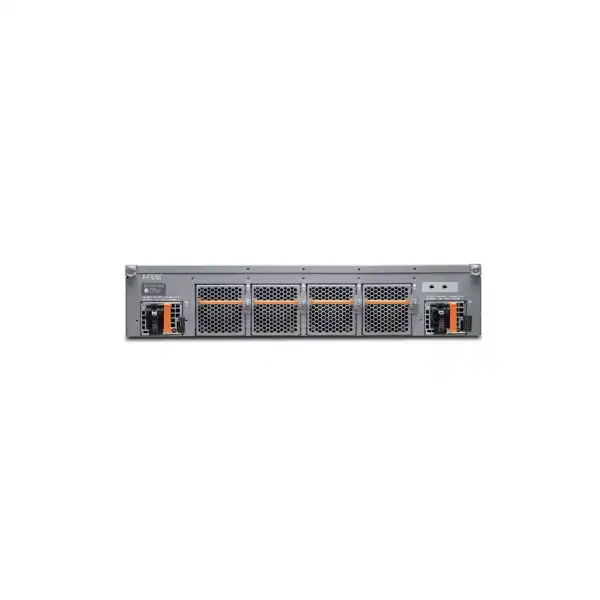
| Power supplies | Redundant 1+1 hot-pluggable 1100 W AC or DC options | A and B power feeds should be planned separately when true power-path resilience is required. |
| Cooling | Front-to-back or back-to-front; redundant N+1 hot-pluggable fan modules | The airflow direction must match the hot-aisle/cold-aisle design. Mixing incompatible airflow components is not a valid installation method. |
| Operating system | Junos OS on standard QFX5210 configurations | Feature availability depends on the selected software release and entitlement. The desired feature set should be checked before choosing an image or license tier. |
Port planning: turn 64 QSFP28 interfaces into a usable fabric design
Port planning is the first place where an apparently simple QFX5210 bill of materials can become complicated. The switch has 64 QSFP+/QSFP28 interfaces, but a project rarely uses every port in exactly the same way. A spine role may use a large number of native 100GbE links to leaf switches. A leaf or access role may use a mixture of 100GbE uplinks and channelized 25GbE server-facing links. Some environments still need 40GbE links to storage or legacy fabric equipment, while selected 10GbE connections may be retained for appliances that have not yet moved to 25GbE.
Juniper’s published deployment examples are a good starting point because they show supported design intent rather than an abstract maximum. A 64 × 100GbE configuration is directly aligned with a dense spine or leaf fabric. Another published example uses 96 × 25GbE plus 8 × 100GbE for 25GbE access. That combination is important because it demonstrates how the QFX5210 can concentrate many server links while preserving high-speed fabric uplinks. It also gives buyers a practical warning: do not multiply 64 ports by four and assume that every theoretical breakout lane can be used at 25GbE simultaneously. Channelization constraints, port groups and supported combinations must be checked against the exact Junos release and hardware configuration.
The media plan is equally important. A 100GbE port can be connected with direct-attach copper, active optical cable or optical transceivers depending on distance, rack layout and interoperability requirements. Breakout applications require the correct fan-out cable or optic arrangement. For multimode or single-mode fibre, connector type, fibre grade, patch-panel design, optical budget and transceiver qualification all matter. When links leave the rack, a design based purely on cable length can miss patching loss, intermediate panels or future moves. A proper bill of materials maps every logical link to an exact physical path and then chooses an optic or cable that covers that path with reasonable margin.
For brownfield Dubai data centers, the safest approach is to create a port schedule before ordering. Each row should identify the source and destination device, required speed, cable distance, fibre type, connector type, whether breakout is required and whether the far-end device supports the same FEC and negotiation behavior. This small engineering step often prevents more procurement rework than any later configuration change because it catches physical incompatibilities while they are still inexpensive to correct.
100GbE spine role
As a spine, the QFX5210 is attractive when the leaf layer needs many 100GbE uplinks and the design is intentionally built around a 100GbE fabric. The 64-port density can support a sizeable Clos topology without moving immediately to a modular chassis. The real sizing variable is not the number of servers but the number of leaf-facing fabric links. A pair or larger set of spines is normally designed so every leaf has equal-cost paths through the fabric, and the required spine count follows from leaf count, links per leaf, resilience target and expected growth.
This role suits organizations that value a simple fixed-switch architecture and can keep the entire fabric within the 100GbE speed class. If the design already requires 400GbE or 800GbE spine links, a newer QFX platform should be evaluated instead of forcing the QFX5210 into a roadmap it was not designed to satisfy.
25GbE leaf or access role
A 25GbE server-access design can use QSFP28 breakout to present multiple lower-speed server-facing interfaces while keeping selected 100GbE ports for uplinks. This is useful for virtualization clusters, dense compute racks and storage environments that have standardized on 25GbE NICs. The design should calculate oversubscription from actual server-facing capacity and uplink capacity, then determine whether that ratio remains acceptable during failures or maintenance when one uplink is unavailable.
Do not treat breakout as a cabling afterthought. The fan-out type, transceiver choice, port channelization capability and server NIC interface all have to line up. When the far end uses SFP28, the selected breakout assembly must be supported by both sides and practical for the rack’s cable-management system.
Junos OS, routing and fabric capabilities
The QFX5210 is not valuable only because it forwards packets quickly. Its operating model is based on Junos OS, giving data center teams a familiar configuration, routing and automation environment across a large part of the Juniper portfolio. Published capabilities include Layer 2 switching, static routing, OSPF, BGP, IS-IS, IPv6, filter-based forwarding, VRRP, multicast functions, quality-of-service controls, traffic mirroring, sFlow, SNMP, XML management, configuration rescue and rollback, zero-touch provisioning and scripting or automation hooks. Exact availability still depends on the installed release, feature support on this hardware and the selected entitlement.
For modern data center fabrics, EVPN and VXLAN are usually the most important architectural features to evaluate. EVPN supplies a control-plane mechanism for distributing reachability information, while VXLAN extends Layer 2 segments over a Layer 3 underlay. Together they can support scalable segmentation and workload mobility patterns without relying on large spanning-tree domains. QFX5210 documentation supports EVPN over VXLAN, but the detailed behavior varies by Junos release. For example, Juniper documentation notes that VXLAN routing support on QFX5210 is available from Junos OS 21.3R1, illustrating why the target software version is part of the design rather than an administrative detail to decide after installation.
A production design should therefore define the control plane first. If the underlay will use eBGP, OSPF or IS-IS, confirm that the operational team already has route policy, addressing and troubleshooting standards for that protocol. If EVPN-VXLAN is required, identify the gateway model, anycast gateway approach, route types, multihoming method, VLAN-to-VNI mapping and automation system. When those decisions are clear, the QFX5210 can be evaluated against a specific fabric blueprint instead of a generic feature checklist.
Licensing: define the feature set before the purchase order
Licensing is one of the most important procurement dependencies for the QFX5210 because the same hardware can be used for different network roles. Juniper’s current QFX licensing documentation places the QFX5210-64C in Class 3 and provides Flex three-tier software options. The current tier structure includes Advanced 1, Advanced 2 and Premium 1 entitlements, offered as perpetual or subscription licenses. The entitlement tables show different feature groups across those tiers, and Juniper explicitly cautions that inclusion of a feature in a license does not automatically mean the feature is supported on every hardware platform or release. The hardware capability, Junos support and license must all align.
Advanced 1
The current Class 3 entitlement table includes functions such as BGP, IS-IS, OSPF, VRRP, filter-based forwarding, GRE, sFlow and EZ-LAG. This tier can make sense for routed underlay designs where the required control-plane functions are included and overlay capabilities are not needed.
Advanced 2
The current Class 3 table adds capabilities including EVPN-VXLAN, VXLAN, ESI-LAG, multicast functions, connectivity fault management and other advanced features. This tier is especially relevant when the QFX5210 is part of an EVPN-VXLAN fabric rather than a simpler routed network.
Premium 1
The current Class 3 table adds service-provider-style functions such as EVPN-MPLS, L2 Circuit, L3 VPN, LDP, RSVP and Segment Routing. It should be evaluated where MPLS or more advanced transport features are part of the target design.
Older environments may still reference legacy Junos base, advanced or premium licensing language. That is why a renewal, expansion or replacement quote should not be built from a license name remembered from an older deployment. The exact device serial entitlement, desired Junos release, migration plan and current commercial licensing program should be checked together. This is particularly important when adding new QFX5210 units to an installed fleet purchased under an earlier licensing model.
For procurement, state the actual feature requirement rather than simply requesting the highest license. For example, specify whether BGP underlay, EVPN-VXLAN overlay, ESI-LAG multihoming, MPLS, segment routing, advanced telemetry or another feature is mandatory. The quotation can then include the appropriate entitlement and term without paying for unrelated capability or discovering later that a required feature was omitted.
Routing scale and forwarding-table considerations
A data center switch should be sized not only by ports but also by the amount of state it must hold. Juniper publishes unidimensional scale figures for the QFX5210 that include up to 264,000 MAC addresses, 4,096 VLAN IDs with several reserved internally, IPv4 route capacity around 262,140 entries, IPv4 host capacity around 204,750 entries, IPv6 route capacity around 172,016 entries, IPv6 host capacity around 102,339 entries, approximately 49,000 ARP entries and 32,000 MPLS labels. These are useful reference points, but the word unidimensional matters: maximum values are normally measured with one resource stressed in isolation. A real configuration consumes multiple forwarding resources simultaneously.
For a straightforward leaf-spine fabric, the most useful question is which state will be programmed into every switch. A routed underlay may carry only infrastructure prefixes, while an EVPN overlay can add MAC, IP and route information associated with tenant workloads. A centralized gateway design distributes state differently from a distributed gateway design. Security policy, access-control lists and large numbers of logical interfaces can consume other hardware resources. If the deployment is approaching published limits, the design should be modeled using the intended feature combination rather than assuming every maximum can coexist.
The same reasoning applies to LAGs and ACLs. The published platform scale includes up to 64 link aggregation groups and up to 64 ports per LAG, while firewall-filter resources are divided between ingress and egress use cases. These numbers are useful for validating a design with server bonds, appliance clusters or aggregated uplinks, but they should not be treated as a guarantee for an arbitrary mixed policy set. A proof-of-concept or detailed feature validation is sensible for environments with unusually large ACL tables, heavy multicast state or complex policy combinations.
This is also where growth planning becomes more precise. If the current environment already carries hundreds of thousands of host or route entries, the question is not whether the QFX5210 can boot with that state today, but whether it leaves operational headroom for failover, maintenance, future racks and new overlays. A switch that is technically within limits but routinely close to its resource ceiling creates a fragile operational posture. Capacity headroom should be treated as a design requirement.
Packet buffer and congestion
The QFX5210 publishes 42 MB of total packet buffer. That figure should be interpreted in context. In a well-designed low-latency Clos fabric, traffic is spread across multiple links and congestion is managed by capacity, equal-cost routing and queue policy. A larger buffer alone does not solve chronic oversubscription. Conversely, workloads with synchronized bursts, storage incast or elephant flows can still expose queue pressure even when aggregate link capacity looks sufficient.
Before using the switch for latency-sensitive storage or specialized workloads, confirm traffic characteristics, queue requirements, loss tolerance and whether priority flow control or other data-center-bridging behavior is required. The correct answer may involve fabric tuning, a different oversubscription ratio or a platform with a buffering architecture better suited to the workload.
Latency and forwarding behavior
Juniper publishes store-and-forward latency around 600 ns for the platform. That is a useful indicator of the switch’s data center orientation, but application latency is the sum of many components: server NICs, virtualization, fibre distance, congestion, queueing, routing path and application behavior. A low switch forwarding latency cannot compensate for a congested fabric or poorly distributed traffic.
When low latency is a formal requirement, define it at the service level. Measure not only idle-path latency but also behavior during peak load, maintenance events and link failures. This creates a realistic acceptance test for the whole network rather than relying on a single device specification.
Power design for Dubai data centers
The QFX5210 uses redundant hot-pluggable 1100 W power-supply options and can be ordered for AC or DC environments. Juniper’s current hardware guidance publishes typical AC power consumption of about 357 W and maximum AC consumption of about 655 W under its stated test conditions. For DC variants, typical consumption is published around 383 W with a maximum around 696 W. These figures are much more useful for facility planning than the power-supply nameplate alone, but neither should be treated as a universal real-world draw. Transceiver choice, traffic load, temperature and component variation influence consumption, and Juniper’s typical figure excludes transceivers.
A resilient installation normally connects the two power supplies to independent power sources so the loss of one feed does not remove both supplies at once. The rack PDU rating, connector type, available circuit capacity and upstream UPS or generator strategy should be checked before delivery. In a data center with many QFX5210 switches, thermal planning should use realistic total rack power rather than multiplying only the typical switch figure. High-power optics can add a meaningful amount of heat, and a dense 100GbE rack may contain dozens of transceivers.
The UAE context makes temperature control particularly important. Outdoor conditions are not the operating environment for a data center switch; the relevant figure is the temperature at the equipment air intake. Juniper publishes an operating temperature range of 0°C to 40°C and operating relative humidity of 5% to 90% non-condensing. Cooling design should therefore keep the switch within its specified inlet conditions even during chiller maintenance, partial cooling failure or high rack load. A room that is generally cool but has poor front-to-back airflow can still create local hot spots at dense switches.
Power and cooling should be finalized with the exact airflow variant because the fan and PSU orientation are part of the chassis thermal path. A purchase order that lists only QFX5210-64C without the required airflow and power details is incomplete for a production deployment. The rack’s hot-aisle/cold-aisle direction, PDU arrangement and preferred AC or DC architecture should be part of the quotation request.
Airflow orientation: a small suffix with large operational impact
QFX5210 hardware is available with different airflow directions. Juniper describes FRU-to-port airflow and port-to-FRU airflow, and the current hardware compatibility information shows AFI and AFO variants across AC and DC configurations. In operational terms, this must match the cabinet’s cold-aisle and hot-aisle layout. If the front of the switch faces the cold aisle, choose the airflow direction that draws cool air from that side and exhausts it toward the hot aisle. Reversing that relationship can cause the switch to ingest heated exhaust air from neighboring equipment.
The fan and power-supply components must also be consistent with the chassis airflow. Juniper’s hardware guide warns against mixing power supplies with different airflow or wattage and identifies separate fan modules for the two airflow directions. This is not cosmetic labeling. The system’s thermal design assumes a predictable direction of air movement across the internal components. A spare-parts strategy should therefore keep the correct fan and PSU variants for the installed fleet.
Another published environmental detail deserves attention: the current datasheet lists AFO models for operation up to 6,000 feet, while AFI models are listed for sea-level operation. Dubai itself is a low-altitude location, but UAE deployments are not always in the same environment. If equipment will be installed at a different altitude or in a special industrial location, validate the environmental specification for the exact ordered variant rather than applying a generic QFX5210 assumption.
Optics, DACs and breakout cables: build the physical layer before ordering
A high-speed switch quote can be incomplete even when the correct chassis is listed. The transceiver and cabling plan often represents a substantial part of the project cost and determines whether the network can actually be connected on installation day. The QFX5210 uses QSFP-class interfaces for its 40GbE and 100GbE connectivity, with channelization for selected lower-speed uses. Each link should be assigned a media type based on distance, fibre plant and operational requirements.
For very short intra-rack links, direct-attach copper can be economical and operationally simple, provided the cable length and supported part are appropriate. For nearby racks, active optical cables can reduce transceiver and patching complexity, but they create a fixed cable assembly that may be less flexible for structured cabling. Optical transceivers are preferable when the network uses patch panels, longer links or existing fibre infrastructure. Multimode and single-mode optics serve different distance and fibre-plant requirements, and connector type must be compatible with the installed panels. A generic statement such as ‘100G fibre’ is not enough for procurement.
Breakout links deserve a dedicated schedule because one physical QSFP28 port becomes several logical interfaces. The far-end ports may be SFP28 or SFP+, and the cable must fan out accordingly. Operators should decide how breakout strands will be labeled, routed and documented, because troubleshooting a four-way fan-out becomes difficult if the physical branches are not tied clearly to logical interface names. This is especially relevant when dozens of server links are concentrated into a small number of switch ports.
Optic qualification should also be handled carefully. Juniper provides hardware compatibility information for qualified transceivers and cables, while its hardware guidance cautions that high-power third-party optical modules can create thermal or support concerns. If the project intends to use third-party optics, that should be a deliberate engineering and support decision rather than a surprise during installation. Confirm power draw, thermal behavior, DOM support, alarm behavior, warranty implications and interoperability with the far-end device.
For a quotation, provide FourTeck with the number of 100G, 40G, 25G and 10G links, approximate distance for each link class, fibre type where known and whether the connection is intra-rack, inter-rack or across a structured cabling system. That allows the chassis, optics, DACs, fan-out assemblies and patching accessories to be reviewed as one system.
Management, telemetry and day-two operations
The strongest data center designs are built around how the network will be operated after commissioning. The QFX5210 provides a dedicated RJ-45 management port, a console interface and a USB port in addition to the switching interfaces. These should be incorporated into an out-of-band management design so engineers can reach the switch even when the production fabric is impaired. The management network should have its own addressing, access control, authentication and monitoring plan rather than being treated as an optional cable added after the rack is built.
Junos operations include role-based CLI access, configuration rescue and rollback, image rollback, SNMP, XML management, high-frequency statistics collection, sFlow, local and remote traffic mirroring and scripting or automation mechanisms. These tools are most valuable when they are integrated into standard procedures. For example, configuration changes can follow a controlled commit process, monitoring can collect interface errors and utilization trends, and sFlow or telemetry can help identify changing traffic patterns before congestion becomes an incident.
Zero-touch provisioning can reduce manual work when many switches are deployed, but it should be paired with a secure bootstrap process and a source-controlled configuration model. The goal is not simply faster initial configuration. A repeatable template makes replacement and expansion easier because the network state can be reconstructed from automation rather than from undocumented command history. For multi-rack projects, this operational consistency often provides more long-term value than a marginal difference in switch hardware price.
Before procurement, identify the existing toolchain: configuration management, IP address management, syslog, SNMP or streaming telemetry collectors, backup systems, AAA servers and automation platforms. Confirm that the planned Junos release and feature set integrate with those systems. A switch that technically supports the required protocol can still create operational friction if the surrounding monitoring or automation platform expects a different data model or software version.
High availability: design resilience at the fabric level
The QFX5210 contains redundant hardware elements, including 1+1 power supplies and N+1 fan modules, but data center availability cannot be reduced to internal component redundancy. The more important question is what happens when an entire switch, rack, uplink or maintenance domain becomes unavailable. A leaf-spine architecture should provide alternate paths so traffic can continue through another spine or, where the application design allows, another leaf. This requires multiple physical links, routing convergence, correct ECMP behavior and enough surviving bandwidth to carry the remaining load.
Juniper lists Bidirectional Forwarding Detection and uplink failure detection among the platform’s high-availability capabilities. BFD can provide rapid failure detection for routed adjacencies, while routing protocols determine the control-plane response. For EVPN fabrics, multihoming and ESI-LAG may be part of the server or appliance resiliency model, subject to the required license tier and supported software release. The exact architecture should distinguish between link failure, device failure and maintenance; each scenario can have different forwarding behavior.
Capacity under failure is often overlooked. If a leaf normally has two 100GbE uplinks and either one can carry the full peak workload, the design has strong single-link resilience. If both uplinks are required to support normal traffic, a failure may not disconnect the rack but can create congestion severe enough to affect applications. The same applies to spines: losing one spine changes the available fabric capacity. Redundancy should therefore be measured in surviving throughput as well as in the number of remaining paths.
Operational processes complete the design. Maintenance windows should be tested using graceful shutdown or routing procedures, software upgrades should follow a validated path, and configuration rollback should be part of the change plan. A resilient network is one in which routine work can occur without unexpected traffic loss, not simply one that contains duplicate hardware.
Security and segmentation considerations
The QFX5210 includes the controls expected from an enterprise data center switch: interface filters, routing filters, VLAN controls, DHCP snooping, storm control, management authentication through RADIUS or TACACS+, SSH access, control-plane denial-of-service protections and logging or traffic-mirroring functions. These capabilities support a layered security design, but the switch is not a replacement for a next-generation firewall where application inspection, threat prevention or advanced security policy is required.
In an EVPN-VXLAN fabric, segmentation can be designed around VRFs, VLANs and VNIs, separating tenant or application traffic while using the routed fabric for transport. The security model should define where policy enforcement occurs. Some organizations use the fabric primarily for segmentation and route isolation, then direct traffic through firewalls for inspection. Others use distributed routing and apply network filters for specific east-west controls. The QFX5210’s role should be chosen in conjunction with the security architecture so that the network does not create unintended bypass paths.
Management-plane security deserves separate attention. The dedicated management interface should be placed on an isolated administrative network, with access limited to approved management hosts or jump servers. Centralized AAA helps enforce individual accountability, while syslog and configuration archives provide change visibility. Protocols and services that are not required should be disabled or restricted. The operational goal is to make the out-of-band network more trustworthy than the production network it controls.
For buyers replacing an existing switch, collect the current VLAN, VRF, ACL, routing-policy and management-access requirements before migration. A new platform may have more capability, but a secure migration still depends on reproducing the intended controls accurately and removing legacy exceptions that are no longer required.
A practical QFX5210 deployment workflow
Define fabric role
Decide whether each unit will be a spine, leaf, server-access switch or part of a transition design. Count required links and map failure domains.
Create port schedule
List every connection with speed, distance, media, breakout requirement and far-end interface. Reserve capacity for growth and maintenance.
Select airflow and power
Match AFI or AFO direction to the rack, choose AC or DC, and confirm independent feeds, PDU connectors and spare components.
Lock software design
Choose the Junos release and required routing, EVPN-VXLAN, MPLS or telemetry features, then map them to the correct entitlement.
Stage and validate
Load the approved software, apply configuration templates, test optics, verify routing, confirm telemetry and perform failure testing before production cutover.
Migrate with rollback
Move links in controlled groups, monitor errors and utilization, and retain a documented rollback point until applications and network telemetry confirm stability.
Migration from an older 10GbE or 40GbE data center network
Many QFX5210 projects are not greenfield fabrics. They replace or augment older networks built around 10GbE server links and 40GbE aggregation. A successful migration starts by separating physical, Layer 2, Layer 3 and application dependencies. Physically, the project may need new 25GbE server NICs, QSFP28 optics, breakout cables and fibre patching. At Layer 2, VLAN IDs, trunking, LAGs and spanning-tree behavior must be understood. At Layer 3, routing protocols, route policies, static routes, VRFs and gateway addresses must be mapped. Application teams then need to confirm which services depend on Layer 2 adjacency, multicast, fixed source addresses or security zones.
The QFX5210 can participate in a staged migration because it supports multiple Ethernet speeds. That flexibility does not remove the need for a transition plan. A mixed-speed environment can become operationally confusing if temporary links remain indefinitely. Define which 10GbE and 40GbE connections are transitional, which are permanent and what event triggers the next upgrade. Reserve sufficient ports so the switch does not become full during the migration itself, when old and new links may coexist for a period.
If the target architecture introduces EVPN-VXLAN, the project is more than a switch replacement. The team is moving from a traditional VLAN-centric network to an overlay model with a routed underlay and a separate control plane. That change should be staged and tested. Addressing, BGP or IGP design, VNIs, route targets, anycast gateway configuration and multihoming policy need clear standards. Monitoring tools and troubleshooting procedures should be updated before the first production workload depends on the new fabric.
A controlled migration is usually faster than an improvised one because rollback is possible at each stage. The old network can remain available until the new fabric has passed link, routing, application and resilience tests. This reduces the temptation to troubleshoot multiple physical and control-plane changes simultaneously during a short maintenance window.
Where the QFX5210 fits well
100GbE leaf-spine fabrics
The platform is a natural fit where 100GbE remains the planned fabric speed and high port density is needed in a fixed 2U switch. It can provide many equal-cost links without the space and operational model of a modular chassis.
25GbE server access
Published breakout deployment patterns support dense 25GbE access while retaining 100GbE uplinks, making the switch useful for compute racks moving beyond 10GbE server connections.
EVPN-VXLAN fabrics
With the appropriate Junos release and license tier, the QFX5210 can be part of an EVPN-VXLAN architecture for scalable segmentation and routed fabric designs.
Hosting and private cloud
High east-west traffic, virtualized workloads and a need for predictable fabric paths align well with the QFX5210’s dense high-speed interface model.
Service-provider infrastructure
Advanced routing and, with the correct entitlement, MPLS functions can support provider or multi-tenant designs where a fixed 100GbE switch meets the scale and interface requirements.
When a different switch should be evaluated
The QFX5210 should not be recommended automatically for every data center project. Its strength is dense 100GbE-class switching, so the first reason to consider another platform is a different speed roadmap. If new servers, storage systems or spine links already require 200GbE, 400GbE or 800GbE, a newer high-speed QFX design is likely to provide a cleaner lifecycle path. Buying a 100GbE switch for a fabric that is expected to move immediately to 400GbE can create an early replacement cycle even if today’s traffic technically fits.
A smaller switch may also be more appropriate. If the environment needs only a modest number of 10GbE or 25GbE ports and a few 100GbE uplinks, the QFX5210 can provide far more high-speed density than required. Lower-density equipment may reduce capital cost, power draw and optic count while still meeting resilience needs. Conversely, a much larger fabric may be better served by 400GbE or higher-speed spines because the number of 100GbE links needed between tiers becomes operationally and physically cumbersome.
Buffering requirements can be another differentiator. The QFX5210’s published 42 MB packet buffer suits many high-speed IP fabric workloads, but specialized environments with unusually bursty traffic or strict lossless-storage behavior should be validated against actual traffic patterns. The correct platform decision may depend more on queue and buffer architecture than on headline throughput.
Finally, consider software and operations. If the organization has standardized on a different network operating system, automation stack or management platform, the migration cost may outweigh the hardware benefit. A technically excellent switch still needs to fit the team’s operational model, support process and lifecycle plan.
Sizing a QFX5210 fabric without relying on headline bandwidth
Fabric sizing begins with traffic, not with the maximum throughput number. Start by counting server-facing interfaces and classifying their speeds. Estimate how much of that capacity can be active at the same time, then identify where traffic goes. East-west application traffic may remain inside the fabric, north-south traffic may cross firewalls or edge routers, and storage traffic can have a different peak pattern from ordinary application traffic. These flows determine uplink demand and oversubscription.
Consider a rack with many 25GbE servers. The theoretical sum of NIC line rates can be much larger than the rack’s real sustained traffic. A leaf does not always need one-to-one uplink bandwidth, but the acceptable oversubscription ratio depends on workload behavior. A general virtualization rack may tolerate a higher ratio than an HPC or storage-heavy cluster. The correct ratio should also be tested during failure. If the rack has four 100GbE uplinks and can lose one without congestion, that is a stronger design than one that needs all four simply to support normal peaks.
At the spine layer, calculate the number of leaf-facing links each spine must terminate. Then reserve ports for growth, maintenance or migration. Filling every spine port on day one leaves no easy path to add a rack without recabling or installing another spine. A capacity model should include at least the expected project horizon, not only the first installation phase.
Route and MAC scale must be checked alongside interface capacity. If the fabric uses EVPN, determine how many endpoints, prefixes and tenant segments each device will learn. If the design uses large ACLs or extensive multicast, include those resources in the validation. The published maximum table is a starting point, but a production configuration combines resources and feature interactions.
Finally, compare the result against the lifecycle plan. If the network will remain centered on 25GbE servers and 100GbE fabric links for several years, the QFX5210 can be a rational fit. If 100GbE is only an interim step before 400GbE, the design should compare the cost of using QFX5210 now with the cost and disruption of replacing it later. A good sizing exercise therefore includes time as well as bandwidth.
Installation and rack-readiness checklist
Rack space and depth
Reserve 2U and verify cabinet depth, rail compatibility, rear service clearance and cable-management space. The published depth is about 61.2 cm including the fan handle, so shallow racks should be checked carefully.
Airflow alignment
Confirm the data center’s cold-aisle/hot-aisle direction before choosing AFI or AFO hardware. Keep spare fans and power supplies matched to that orientation.
Power feeds
Identify AC or DC, connector and PDU requirements, and connect the redundant supplies to independent sources when the facility design supports A/B feed resilience.
Structured cabling
Verify fibre type, connector type, patch-panel loss and cable path. Label breakout strands and reserve bend-radius space for dense QSFP cabling.
Out-of-band management
Provide management and console connectivity before production cutover. Confirm AAA, NTP, DNS, syslog, monitoring and configuration-backup reachability.
Staging location
Plan a place to unpack, inspect, power on, update and test the switch before it enters the production rack. Staging catches shipping, optic and software issues early.
Software release selection and lifecycle planning
A QFX5210 deployment should have an explicit software policy. The newest available Junos image is not automatically the correct production release, and an old image should not be retained indefinitely only because it is familiar. Choose a release that supports the required features, optics and interoperability, has an appropriate support status and has been validated against the organization’s operational tooling. If EVPN-VXLAN routing, specific transceivers or another feature was introduced or changed in a particular release, that dependency should be documented.
For an existing Juniper environment, compare the target QFX5210 release with other devices in the fabric. Mixed releases are sometimes necessary, but they can complicate troubleshooting and feature consistency. A standard release train reduces variance across configuration syntax, telemetry and known behavior. The upgrade plan should include rollback, configuration compatibility and the expected impact on routing adjacencies or traffic.
Lifecycle planning also includes support entitlement and spare strategy. A data center switch is usually part of a critical path, so define the acceptable replacement time for a failed unit. On-site spare hardware may be justified in large or remote facilities even when vendor support is in place. Keep compatible power supplies, fans, optics and cables where a single component shortage could extend downtime. The correct spare inventory depends on the number of installed units and how quickly replacement parts can reach the site.
Before buying QFX5210 hardware for a new multi-year program, confirm the current product lifecycle status and support horizon with the supplier and manufacturer. Data center switches can remain technically useful long after newer generations appear, but a project should understand how long software maintenance, security fixes and hardware replacement services will remain available. This is especially important when the equipment will be standardized across multiple UAE facilities over several rollout phases.
Procurement risks that a complete QFX5210 quotation should remove
The lowest chassis price is not necessarily the lowest project cost. A complete QFX5210 purchase may require the switch hardware, correct airflow and power variant, rail or rack-mount kit, optics, direct-attach or active optical cables, breakout assemblies, software entitlement, support coverage and installation services. Some items depend directly on topology. For example, two switches with identical chassis part numbers may require very different optic counts because one is used as a spine and the other as 25GbE server access.
The first procurement risk is an underspecified part number. ‘QFX5210’ describes the platform family, but production ordering must resolve the exact QFX5210-64C variant, airflow direction, AC or DC power and any bundled or regional details. The second risk is unsupported media. An optic can match the physical connector and nominal speed yet still fail qualification, FEC or interoperability requirements. The third risk is software entitlement: the desired EVPN, VXLAN or MPLS design may need a specific tier even though basic switching and routing features work without it.
Support should be treated as part of system availability. Confirm the required service level, response time, replacement process, coverage term and local logistics. For sites with strict uptime requirements, compare the cost of premium support with holding a spare switch on site. For multi-year projects, align hardware support with software subscription terms so the environment does not reach a renewal mismatch where the device is covered but a required feature entitlement has expired.
Import, delivery and site-readiness timing also matter in Dubai. High-speed optics and specific airflow variants can have different lead times from the base chassis. If the project schedule is fixed, the bill of materials should be finalized early enough to source the exact configuration rather than substituting incompatible components near the installation date. Staging should occur before the maintenance window so firmware, licenses and optics are verified while there is still time to resolve exceptions.
A strong quotation therefore looks more like an engineered deployment package than a single-line hardware offer. It should make assumptions visible, list what is included and excluded, and tie optional items to a clear technical reason. This lets the buyer compare suppliers on equivalent scope instead of comparing a bare chassis price with a complete production-ready package.
Key buyer questions before selecting the Juniper QFX5210
Is 100GbE the right fabric speed?
If the project is firmly within a 100GbE fabric lifecycle, QFX5210 density can be compelling. If 400GbE is already required or imminent, compare newer platforms before committing.
What is the exact port mix?
Count native 100G and 40G ports plus every 25G or 10G breakout. Use a port schedule to verify supported combinations and leave growth capacity.
Which fabric control plane is planned?
Define underlay routing and whether EVPN-VXLAN, ESI multihoming or MPLS is required. The answer drives configuration, training and licensing.
What optics and reach are required?
Separate intra-rack DACs from inter-rack optical links, record fibre types and distances, and validate every far-end interface.
How resilient must each rack be?
Calculate surviving bandwidth after a link or switch failure. Redundant paths that cannot carry the reduced-capacity workload may still create application impact.
Is the facility ready?
Verify 2U rack space, depth, airflow direction, inlet temperature, power feeds, PDU capacity, management connectivity and cable-management space.
Frequently asked questions about QFX5210 deployment
How many 100GbE ports does the QFX5210 provide?
The QFX5210-64C provides 64 QSFP+/QSFP28 ports. Juniper publishes a 64 × 100GbE spine/leaf deployment. The platform also has two SFP+ network ports, while management uses a separate RJ-45 interface.
Can it connect 25GbE servers?
Yes, the QSFP28 interfaces support channelization for 25GbE use. Juniper publishes a 96 × 25GbE plus 8 × 100GbE example. Exact port groups, breakout components and software support should be confirmed for the planned design.
Does QFX5210 support EVPN-VXLAN?
Juniper documents EVPN over VXLAN for QFX5210. Current licensing places EVPN-VXLAN in the Advanced 2 tier for QFX Class 3 devices. Confirm the target Junos release and feature behavior before implementation.
Is it suitable for a data center spine?
Yes, a 64 × 100GbE configuration is one of the published spine/leaf use cases. The design still needs enough spine ports and surviving bandwidth for the number of leaves, growth and failure scenarios.
What is its switching capacity?
Juniper publishes up to 12.8 Tbps bidirectional system throughput and up to 4.2 Bpps forwarding capacity. Real deployment performance still depends on configuration, traffic patterns and feature use.
How much rack space does it need?
The QFX5210 is a 2U switch. Published depth is about 61.2 cm including the fan handle, so check cabinet depth and rear service clearance before delivery.
Does it have redundant power?
The platform supports two hot-pluggable power supplies in a 1+1 redundant arrangement. For true power-path resilience, connect the supplies to appropriately separate feeds rather than to the same upstream source.
What is typical power consumption?
Juniper publishes typical power around 357 W for AC and 383 W for DC under stated test conditions, excluding transceivers. Maximum published values are 655 W AC and 696 W DC. Facility planning should account for optics and actual load.
Which airflow direction should be ordered?
Choose the AFI or AFO orientation that matches the rack’s cold-aisle and hot-aisle direction. Fans and power supplies should use the matching airflow orientation.
Can existing 40GbE equipment remain connected?
The platform supports 40GbE on its QSFP-class ports, which can help with staged migration. Validate the specific optic, cable, FEC and far-end interoperability rather than assuming every legacy module will work.
Is a license required for BGP or EVPN?
Current QFX Class 3 licensing places BGP in Advanced 1 and EVPN-VXLAN in Advanced 2. Licensing programs change over time, so the quote should be based on the current entitlement model and exact required features.
Is it the best choice for a new 400GbE fabric?
No. The QFX5210 is fundamentally a 100GbE-class platform. If the new design requires 400GbE or higher fabric interfaces, evaluate newer QFX platforms rather than planning an immediate second migration.
Dubai and UAE deployment considerations
Deploying a QFX5210 in Dubai follows the same technical standards as any other enterprise data center project, but local conditions can change procurement and facility decisions. The most obvious issue is climate: the switch belongs in a controlled data center or communications environment where inlet temperature and humidity remain within specification. The external summer temperature is not a reason to derate the switch directly, but it increases the importance of reliable cooling infrastructure, airflow containment and facility resilience. Data center operators should check expected inlet temperature during normal conditions and during maintenance or cooling-system failover.
Power architecture varies by site. Many enterprise facilities use AC-backed racks, while carrier and telecom environments may use DC. QFX5210 variants exist for both. The correct choice should match the site’s existing distribution model rather than introducing a separate power standard for one device. For redundant AC feeds, confirm PDU connectors and circuit capacity. For DC installations, verify the exact voltage, cabling, protection and grounding requirements with the facility team and follow the manufacturer’s hardware guide.
Regional procurement should also consider lead time for exact variants. A chassis may be available before the required airflow direction, power supply, optic or software entitlement. For a scheduled migration, lock those details early. If a substitute optic or cable is proposed because the preferred part is delayed, revalidate support and reach rather than treating it as an equivalent based solely on speed.
For organizations operating multiple UAE sites, standardization can reduce support complexity. Use the same airflow convention wherever rack layouts permit, standardize Junos release and configuration templates, keep a controlled list of approved optics and maintain consistent spare strategy. If one facility requires a different airflow direction or power model, make the difference explicit in asset records so components are not swapped incorrectly during an incident.
FourTeck can structure a Dubai quotation around the actual site conditions rather than a generic chassis request. The most useful inputs are the rack layout, required port mix, cable distances, software features, support level and planned migration date. With those details, the proposal can separate mandatory components from optional growth items and make the technical assumptions clear to procurement and engineering teams.
Decision recap: the six choices that determine whether QFX5210 is a good fit
1. Fabric speed
Choose QFX5210 when 100GbE is an intentional fabric target, not merely a temporary step toward an already-required 400GbE design.
2. Port mix
Validate native and breakout combinations for every 100G, 40G, 25G and 10G connection, including growth and maintenance headroom.
3. Software entitlement
Map BGP, EVPN-VXLAN, ESI-LAG, MPLS or segment-routing requirements to the current QFX license tier and supported Junos release.
4. Physical media
Choose qualified optics, DACs, AOCs and breakout assemblies using distance, fibre type, connector and far-end compatibility.
5. Facility fit
Confirm 2U rack space, chassis depth, AFI/AFO airflow, AC or DC power, A/B feeds, thermal headroom and out-of-band management.
6. Lifecycle
Check support coverage, spare strategy, software maintenance horizon and whether the platform remains aligned with the organization’s speed roadmap.
What FourTeck needs for an accurate QFX5210 quotation
A precise request lets the quotation include the right hardware and avoids hidden dependencies. The following inputs are enough to turn a general QFX5210 enquiry into a technically useful bill of materials.
Plan the QFX5210 as a complete fabric component, not a standalone switch
The Juniper QFX5210 can be an effective choice for dense 100GbE data center fabrics and 25GbE server-access designs, but the strongest result comes from matching the switch to the topology, software features, optics, facility and lifecycle plan. FourTeck can review your Dubai or UAE requirements and prepare a configuration that identifies the exact hardware variant, required media, software entitlement, support coverage and implementation scope.

Reviews
There are no reviews yet.