

Cisco Meraki MS150-24P-4G Dubai
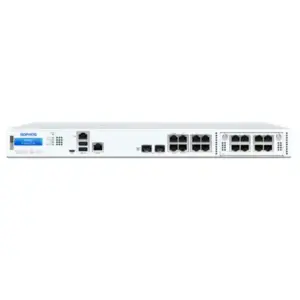
A 24-port Gigabit PoE+ access switch for organisations that want Meraki cloud management, a 370 W PoE budget, four 1 GbE fibre uplinks and dedicated 80 Gbps physical stacking without moving to a 10 GbE uplink model.
4 × 1 GbE SFP
370 W PoE budget
80 Gbps stacking
Meraki Dashboard
Direct answer: what the MS150-24P-4G is and when it fits
What exactly is it?
The Cisco Meraki MS150-24P-4G is a cloud-managed, stackable Layer 2 access switch with static Layer 3 routing capability. It has 24 Gigabit copper access ports, PoE support and four 1 GbE SFP uplink ports.
What is it mainly used for?
It is mainly used as an access-layer switch for wired users, wireless access points, IP phones, cameras, printers, IoT endpoints and other Ethernet devices in branch or campus networks.
Who should consider it?
Organisations that need 24 Gigabit access ports, substantial PoE capacity, cloud operations and physical stacking, while being comfortable with 1 GbE SFP uplinks rather than 10 GbE SFP+ uplinks.
What must be confirmed?
Confirm the Meraki license tier and term, the PoE load of connected devices, fibre transceiver requirements, stacking cables, management connectivity and whether 1 GbE uplinks are adequate for current and future traffic.
What can FourTeck determine?
FourTeck can help map port count, endpoint power, uplink design, license edition, optic type, stack size, rack requirements, migration scope and local deployment services into an accurate UAE quotation.
Where the MS150-24P-4G fits in a modern access network
The MS150 family is positioned by Cisco Meraki as a branch and campus access-switching platform. Within that family, the MS150-24P-4G has a particularly clear role: it gives a site twenty-four conventional 1 Gigabit Ethernet user or device ports, PoE power, four 1 Gigabit SFP uplinks and dedicated physical stacking. That combination matters because it addresses a very common real-world design requirement. Many offices do not need multigigabit copper on every desk, and many branches do not need 10 GbE uplinks from every access switch, but they still want centralised cloud management, a meaningful PoE budget and the ability to build a physical switch stack.
The model is therefore better understood as a balanced access-layer switch than as the fastest member of the MS150 range. Its 24 copper ports are designed for 10/100/1000 Mbps Ethernet connectivity. The four SFP uplinks are 1 GbE rather than SFP+. For a branch with moderate uplink demand, this may be completely appropriate. For a dense wireless environment, a high-volume media workflow, many high-throughput cameras, large local backup flows or a site where access-layer oversubscription must be kept very low, the uplink choice deserves closer examination. Cisco offers MS150 variants with four 10 GbE SFP+ uplinks, so the 4G versus 4X distinction should be a deliberate design decision rather than a small SKU detail.
Power delivery is another defining characteristic. The switch has a 370 W total PoE budget and supports up to 30 W per powered port. This makes it suitable for many access points, IP phones, surveillance cameras and other powered Ethernet devices. The total budget, however, is shared. A design that connects twenty-four devices cannot simply assume that every port may draw 30 W simultaneously: twenty-four times 30 W would exceed the 370 W switch budget. A correct design uses the actual or worst-case power requirement of each endpoint, includes reasonable growth margin and checks whether any endpoint requires more than 30 W. If higher per-port power is required, the MS150 multigigabit PoE++ variants should be considered instead.
The result is a model that can be excellent when its constraints match the site. It is not a generic answer to every 24-port PoE requirement. The strongest purchase case exists when 1 Gigabit client access is sufficient, a 370 W PoE budget covers the planned endpoints, four 1 Gigabit fibre uplinks provide enough aggregate upstream capacity, and Meraki Dashboard operations fit the organisation’s network-management model.
24-port access density
Twenty-four 1 GbE RJ45 ports suit a single wiring-closet segment, a medium office floor, a branch, a classroom block or a device-focused zone where most endpoints operate at conventional Gigabit Ethernet speeds. The port count also leaves room to segregate device types through VLANs without forcing a jump to a 48-port chassis when the physical endpoint count does not justify it.
PoE+ for converged edge devices
The 370 W budget is useful when phones, access points, cameras and selected IoT devices share the switch. Centralised PoE can simplify local power arrangements and supports cleaner UPS planning because endpoint power can be protected through the network rack rather than through many scattered adapters.
Dedicated physical stacking
Two dedicated stack ports provide 80 Gbps stacking bandwidth, and the MS150 family supports physical stacks of up to eight switches. A stack can simplify multi-switch management and increase local scale without consuming ordinary front-panel uplink ports for the stack connection itself.
Cloud-led operations
Meraki Dashboard provides central configuration, visibility, firmware lifecycle handling and remote troubleshooting capabilities. This operational model is particularly valuable for organisations with multiple branches because engineers can work from a common management plane rather than relying only on device-by-device local administration.
Verified MS150-24P-4G technical profile
| Specification | Cisco Meraki MS150-24P-4G | Buyer relevance |
|---|---|---|
| Access ports | 24 × 10/100/1000 Mbps RJ45 | Designed for standard Gigabit endpoints rather than mGig clients. |
| Uplinks | 4 × 1 GbE SFP | Confirm that 1 GbE fibre or copper SFP uplinks provide sufficient upstream capacity. |
| PoE per port | Up to 30 W | Suitable for many PoE/PoE+ endpoints; higher-power devices may require another model. |
| Total PoE budget | 370 W | Total endpoint draw must be calculated rather than assuming 30 W on every port. |
| Dedicated stack ports | 2 | Allows physical stacking without consuming ordinary access/uplink ports. |
| Stacking bandwidth | 80 Gbps | Useful for multi-switch access-layer designs and consolidated management. |
| Switching capacity | 56 Gbps | Matches the port architecture of the 24-port 4G model. |
| Layer 3 capability | SVIs, static routing and DHCP relay | Appropriate for straightforward inter-VLAN routing; not a substitute for a richer dynamic-routing distribution platform. |
| Layer 3 scale | 16 Layer 3 interfaces, 16 static routes, up to 8192 routable clients | Defines the practical boundary for using the MS150 as a local routing device. |
| Management port | 1 dedicated management interface | Supports local status-page access and deployment troubleshooting. |
| Power input | 100–240 VAC | Compatible with standard UAE mains input when deployed with the correct supplied power arrangement. |
| Power load | 22.9 W idle / 422.2 W maximum | Useful for UPS, rack power and thermal planning. |
| Operating temperature | 0°C to 45°C | Rack ventilation and room cooling remain important in UAE deployments. |
| Humidity | 5% to 95% | Environmental conditions should stay within the published operating envelope. |
| Mounting | Integrated 1U rack mount | Fits conventional network racks while keeping access switching compact. |
PoE planning: the 370 W budget is generous, but it still needs calculation
Power over Ethernet is often the reason a buyer chooses the MS150-24P-4G instead of the non-PoE MS150-24T-4G. The switch can deliver up to 30 W on an individual powered port and has a total PoE switch budget of 370 W. This is enough for many mixed office deployments, but the correct sizing method is to work from endpoint requirements rather than from port count alone. A typical branch might have wireless access points, IP phones and surveillance cameras on the same access switch. Their power profiles can be very different, and some endpoints draw significantly more during startup or under full feature load than they do during normal idle operation.
Start with a port-by-port inventory. Record the exact device model, its supported PoE standard and its maximum expected draw. Add the totals and reserve headroom for replacements, firmware changes, device upgrades and future additions. A design that consumes nearly the full 370 W on day one may technically work but leaves little flexibility. In contrast, a design that uses around half to two-thirds of the available budget has more room for growth and reduces the chance that adding one higher-power access point forces an unexpected switch change.
The per-port maximum also matters. The MS150-24P-4G is the 30 W-class model, not the 60 W MS150-24MP-4X. That difference can become decisive with newer high-performance access points, specialist cameras, displays, building systems or other devices that expect PoE++ power above 30 W. A buyer who only looks at the total 370 W figure can therefore reach the wrong conclusion. Total budget answers how much aggregate power the switch can distribute; per-port capability answers whether a particular endpoint can be powered correctly at all.
PoE design also affects the UPS. If the switch is expected to keep phones, access points or cameras alive during a mains interruption, the UPS must be sized for the switch itself plus the attached PoE load. Cisco documents a maximum power load of 422.2 W for the MS150-24P-4G, which is substantially above the 22.9 W idle value. A small UPS selected using only the switch’s base consumption could deliver a much shorter runtime once endpoint power is included. For business continuity, use an actual load estimate and define the required runtime in minutes before selecting the UPS.
Finally, decide which powered devices are business-critical. A branch may prefer to keep voice phones and wireless coverage running during an outage but allow non-critical cameras, displays or lab devices to shut down. That operational priority can be reflected in port policy, UPS sizing and physical switch allocation. The MS150-24P-4G provides the electrical capacity, but the resilience outcome depends on how that capacity is planned.
Uplink design: understand the “4G” in the model name
The four uplink ports on the MS150-24P-4G are 1 GbE SFP interfaces. This is one of the most important facts in the entire buying decision. The MS150-24P-4X is a separate model with four 10 GbE SFP+ uplinks. Both may appear similar in a product list, and both provide twenty-four Gigabit access ports with a 370 W PoE budget, but the uplink architecture is very different. A quotation should therefore preserve the full model suffix rather than describing the requirement only as “MS150 24-port PoE.”
A 1 GbE uplink can be entirely reasonable for a moderate branch. Many user-facing applications are internet-bound, and the site’s WAN service may itself be below 1 Gbps. If most traffic leaves through a firewall or SD-WAN appliance with a sub-gigabit circuit, 10 GbE uplinks may offer limited immediate benefit. The same may apply where the switch serves ordinary desks, phones and low-to-medium-bandwidth cameras with little east-west traffic.
The situation changes when the access switch aggregates high-performance wireless, local servers, large file transfers, video workflows, backup traffic or dense camera streams. Modern wireless access points can generate more than 1 Gbps under favourable conditions, and multiple high-throughput endpoints can converge on the uplink simultaneously. Even if an individual copper access port is 1 GbE, an access switch with many busy ports can place significant load on upstream links. Link aggregation can increase aggregate capacity where the upstream design supports it, but it does not turn a single flow into 10 GbE and it requires careful design on both ends.
Fibre type and transceiver selection are separate procurement decisions. The switch provides SFP slots; the optical modules, fibre patching and upstream compatibility must match the distance and medium. Single-mode and multimode environments require different optics. Copper SFP modules may be relevant in some designs. Existing fibre plant should be inspected for connector type, fibre category, available strands, patch-panel presentation and the specification of the device at the far end. Buying the switch without defining this part of the link can delay commissioning even when the switch itself is available.
For UAE projects, this uplink check is especially useful in refresh work. Older branches often have 1 GbE fibre between communications rooms and can adopt the MS150-24P-4G with minimal backbone change. Newer campuses may already be moving access uplinks to 10 GbE. In that case, the 24P-4X may be the more forward-looking choice. The correct decision depends on measured traffic, application behaviour, backbone design and expected service life rather than on the assumption that higher uplink speed is always necessary.
Physical stacking and scale
Dedicated stack ports
The MS150 provides two dedicated stacking ports, so physical stack connectivity does not consume the four SFP uplinks. Cisco specifies 80 Gbps stacking bandwidth for the family. This is useful when several access switches share a rack or wiring closet and are intended to operate as a coordinated stack.
Up to eight switches
Cisco positions the MS150 for stacks of up to eight switches. This provides substantial port growth inside one access-layer design. A full stack can support hundreds of access ports, although uplink capacity, PoE, failure domains and rack power still need to be engineered for the total deployment.
Stacking cables are separate
The MS150 installation documentation states that stacking cables are not included with the switch and are sold separately. This is a practical quotation dependency. A multi-switch stack should list the required cable type and quantity rather than assuming the base hardware box contains them.
Stacking is valuable, but it should not be treated as a substitute for an overall resilience design. A stack can simplify configuration and create a coherent switching system, while the site still depends on upstream connectivity, power, cooling, fibre paths and the devices connected to the stack. If all stacked switches share one UPS, one rack power circuit or one upstream fibre path, those elements remain common failure points. Resilient projects should consider how power feeds, UPS systems, upstream links and physical cable routes align with the business continuity requirement.
Stack membership also has a lifecycle implication. It is easier to maintain a predictable operational environment when stack members are based on a clear standard and when spare strategy is defined. Mixed hardware generations, changing licensing tiers or inconsistent uplink models can complicate future upgrades. For a site expected to grow from one switch to several, it is useful to decide at the first purchase whether the future stack should remain on the 4G uplink architecture or whether the growth plan points to the 4X or multigigabit versions.
Meraki licensing is a purchase dependency, not an optional extra
The MS150 licensing structure includes Enterprise and Advanced tiers. Cisco documents 1, 3, 5, 7 and 10 year terms for both tiers. In co-termination organisations, MS150 switches in the organisation must use a consistent Enterprise or Advanced license tier, and organisations cannot mix the two editions across the affected switching families where Cisco applies that compatibility rule. This means a new switch purchase should be checked against the customer’s existing Meraki organisation before the license line is finalised.
For the twenty-four-port MS150 models, Cisco identifies LIC-MS150-24-xY for Enterprise license and support and LIC-MS150-24A-xY for Advanced license and support, where the term varies by order. The correct license should be selected according to the organisation’s licensing model, required features and current dashboard estate. Hardware and license should be treated as separate commercial components even though they work together operationally.
Advanced licensing matters when the organisation needs capabilities such as Adaptive Policy and other advanced feature entitlements defined by Cisco. Enterprise licensing may be sufficient for a straightforward branch access deployment. The important point is not to buy Advanced simply because it sounds preferable or to buy Enterprise only to minimise line-item cost. The tier must correspond to the design and the compatibility of the wider Meraki organisation.
Licensing also affects lifecycle planning. A three-year project and a ten-year infrastructure standard imply different renewal processes and budgeting. Procurement teams should identify the intended license term, renewal owner and asset-tracking method at purchase time. This prevents a technically successful deployment from becoming an administrative problem later.
Layer 2 controls and security-oriented access features
The MS150 is primarily an access switch, so its value comes not only from port speed but from the controls applied to those ports. Cisco lists 802.1Q VLAN tagging, 802.1X authentication, IPv4/IPv6 ACL support, DHCP snooping, Dynamic ARP Inspection, broadcast storm control, SNMP/syslog integration, port mirroring, LACP and remote packet-capture capabilities among the family’s features. These controls support a disciplined access-layer design in which user devices, voice, wireless infrastructure, cameras, building systems and guest traffic can be separated and monitored rather than placed into one broad flat network.
VLAN design should reflect business and security boundaries. A phone may need access to call-control services but not to the camera network. A camera may need to reach a recorder or cloud service but should not automatically have broad access to user devices. Wireless access points may transport multiple SSIDs mapped to different VLANs. The switch provides mechanisms that can support these outcomes, but policy still has to be designed. Simply replacing an unmanaged switch with the MS150 does not create segmentation by itself.
802.1X can provide stronger access control by authenticating endpoints or users before granting network access. Its effectiveness depends on the identity infrastructure and on a rollout plan for devices that do not support interactive authentication. Printers, cameras, phones and building systems may require MAC-based exceptions or alternative policy treatment. A migration should therefore inventory endpoint types and not assume every connected device can immediately participate in the same authentication workflow.
DHCP snooping and Dynamic ARP Inspection are valuable protections against common local-network problems, but they depend on correct trust boundaries and address information. Misconfiguration can disrupt legitimate services. In a production change, uplink ports, DHCP server paths, voice services, wireless trunk ports and infrastructure connections should be documented before enforcement is enabled. Policy can then be introduced in stages with monitoring and rollback options.
Remote packet capture is particularly useful for distributed sites. Instead of immediately dispatching an engineer to a branch, an authorised administrator can collect traffic evidence through the Meraki management workflow and investigate issues such as DHCP failure, DNS behaviour, application retransmissions or endpoint connectivity. That operational value is one reason the cloud-management model can reduce support friction across geographically distributed UAE and regional networks.
Static Layer 3 routing: useful at the access layer, but know the boundary
Cisco documents the MS150 as Layer 3 capable with switch virtual interfaces, static routing and DHCP relay. Current guidance lists up to 16 Layer 3 interfaces, 16 static routes and 8192 routable clients for the MS150 platform. These capabilities can be useful when a branch wants selected inter-VLAN routing to happen on the access switch rather than sending every local flow to a firewall or separate router.
A practical example is a branch with a user VLAN, voice VLAN, infrastructure VLAN and several device networks. The MS150 can provide local SVIs and static routes where the design calls for that approach. DHCP relay can forward client requests to a central DHCP service instead of requiring a DHCP server in every VLAN. This can reduce unnecessary traffic paths and keep a simple branch topology compact.
However, static routing is not the same as a feature-rich campus distribution routing platform. Cisco’s higher-tier switching platforms support broader dynamic-routing, redundancy and multicast capabilities that are not the defining role of the MS150. If the project needs OSPF, large route tables, complex first-hop redundancy, advanced distribution-layer convergence or extensive campus-core functions, the design should compare a more capable platform instead of stretching the MS150 beyond its access-layer purpose.
This distinction is especially important in procurement because the presence of “Layer 3” in a specification can be interpreted too broadly. The correct question is not simply whether the switch supports Layer 3. The correct question is which Layer 3 functions the site requires, at what scale, with what resilience, and under what failure conditions. When the requirement is straightforward static inter-VLAN routing, the MS150 can fit well. When routing complexity drives the design, the switch platform should be selected around those routing requirements first.
MS150-24P-4G versus nearby MS150 choices
| Model | Access & PoE profile | Uplinks | When to compare it |
|---|---|---|---|
| MS150-24T-4G | 24 × 1 GbE, no PoE | 4 × 1 GbE SFP | Choose when endpoints do not need switch-supplied power and the same 1 GbE uplink architecture is desired. |
| MS150-24P-4G | 24 × 1 GbE, 370 W PoE, up to 30 W/port | 4 × 1 GbE SFP | Balanced fit for conventional Gigabit access plus PoE when 1 GbE uplinks are sufficient. |
| MS150-24P-4X | 24 × 1 GbE, 370 W PoE, up to 30 W/port | 4 × 10 GbE SFP+ | Compare when backbone capacity, wireless aggregation or future 10 GbE access uplinks are important. |
| MS150-24MP-4X | 16 × 1 GbE + 8 × up to 5 GbE mGig, 370 W PoE with up to 60 W on designated mGig ports | 4 × 10 GbE SFP+ | Compare for higher-power or multigigabit Wi-Fi and IoT requirements where the standard 24P model would constrain endpoint speed or power. |
A good shortlist starts with the constraint that is hardest to change later. If fibre uplink capacity is the likely bottleneck, compare 4G and 4X first. If endpoint power or multigigabit copper is the constraint, compare 24P and 24MP first. If neither PoE nor 10 GbE is needed, the non-PoE 24T-4G may reduce unnecessary hardware capability. This approach keeps the purchase tied to the architecture instead of choosing solely by model hierarchy.
Use cases in Dubai and the UAE
Branch offices
A branch with twenty to forty wired and wireless endpoints can use one or more MS150-24P-4G switches as the access layer. The cloud management model suits distributed IT operations, while PoE supports phones and access points without requiring separate power adapters at every desk or ceiling location.
Education environments
Classrooms, labs and administrative areas often combine wired endpoints, Wi-Fi access points, IP phones and cameras. VLAN separation, central visibility and remote troubleshooting can be useful across multiple buildings, provided uplink bandwidth and PoE draw are sized for the density of each area.
Retail locations
Retail branches may connect POS systems, APs, cameras, back-office PCs, digital systems and building devices. A standardised cloud-managed switch platform can reduce configuration drift across locations and give central teams a repeatable method for monitoring connectivity.
Hospitality and serviced offices
Hotels, serviced-office floors and mixed-use spaces frequently have many PoE endpoints. The MS150-24P-4G can support access points, phones and cameras where 30 W per port is adequate. Traffic segmentation should separate guest, staff, voice, security and building-system services according to the project’s policy.
Distributed enterprise networks
Enterprises with many UAE sites can benefit from one Dashboard-based operational model and standard templates. The design should still account for local WAN speed, fibre availability, endpoint counts, PoE budgets and branch-critical services so that standardisation does not override genuine site differences.
Deployment preparation before the switch reaches site
Meraki’s installation workflow is designed around pre-provisioning. Before an engineer mounts the switch, the device can be claimed into the correct Dashboard organisation and network using order or serial information, the required license can be applied, and the intended configuration can be prepared. This supports a more controlled deployment because VLANs, port profiles, management settings and policies can be reviewed before the maintenance window begins.
Firmware should also be considered before physical installation. Cisco recommends connecting the switch to power and a wired internet connection so required firmware can be applied before final mounting. In a project with many branches, pre-staging can reduce the amount of time technicians spend waiting for upgrades on-site and helps expose licensing or cloud-connectivity problems earlier.
The upstream firewall must permit the outbound connectivity required by the Meraki cloud. Cisco directs administrators to the organisation-specific firewall configuration information available through Dashboard because the current ports and destinations should be taken from the live Meraki guidance. This is an important migration dependency. If an existing firewall blocks required outbound management traffic, the switch can be physically connected yet remain unable to establish normal cloud management.
Management IP addressing must be decided as well. Cisco supports routable management addresses assigned dynamically through DHCP or statically. DHCP reservations can provide predictability without individually configuring every switch. Static addressing may be appropriate where the organisation has a strong infrastructure-addressing standard. Whatever method is used, it should be documented in the IP plan and reachable through the intended management path.
A pre-staging checklist should therefore include serial numbers, site names, network assignment, license tier and term, firmware policy, management addressing, VLAN definitions, uplink configuration, spanning-tree assumptions, PoE policy, port profiles, syslog/SNMP requirements and change-control references. This turns the installation from an improvised onsite configuration exercise into a repeatable deployment process.
Rack, power and environmental planning for UAE sites
The MS150-24P-4G uses an integrated 1U rack-mount form factor and accepts 100–240 VAC input. Cisco lists an operating range of 0°C to 45°C and 5% to 95% humidity. These values define the equipment’s published envelope; they do not eliminate the need for sensible cooling. Communications rooms in the UAE can experience significant heat load, especially when multiple PoE switches, firewalls, UPS systems and servers share a small rack. The room environment should be designed so intake air remains within specification under normal operation and foreseeable cooling interruptions.
PoE increases thermal and power considerations because energy is being delivered through the switch to edge devices. A rack containing several 370 W PoE switches can have a much higher electrical load than a rack of non-PoE access switches. PDU capacity, circuit rating, UPS sizing, cable routing and ventilation should be checked for the planned stack, not for a single device in isolation.
Cisco’s installation guidance calls for sufficient rear clearance to maintain airflow and notes that the building installation should provide appropriate overcurrent protection. The correct power cables and local electrical practice should be used. For business-critical environments, procurement teams should coordinate the network bill of materials with the rack and power plan rather than treating the switch purchase as an isolated IT line item.
Cable management also affects serviceability. Twenty-four copper patch leads, several fibre uplinks and stacking cables can create a dense front and rear rack environment. Use labelled patching, clear colour conventions where the customer standard permits, documented port assignments and enough bend radius for fibre. Keeping stack and uplink cables visibly distinct can make troubleshooting faster during an outage.
The rack plan should leave practical working space for replacement and inspection. An engineer should be able to identify a failed link, replace an optic, trace a patch lead and access the reset or management interfaces without disturbing unrelated circuits. Good physical design is not decorative; it reduces operational risk over the life of the network.
Migration from an existing switch: a practical sequence
Capture the current state
Record port use, VLANs, trunks, spanning-tree settings, LAGs, PoE endpoints, voice configuration, uplinks, fibre optics, management addressing and any security controls. Do not rely on memory or an old spreadsheet when the production switch can be audited.
Validate physical compatibility
Check the rack, power source, fibre type, optic compatibility, patch-panel presentation and copper cabling. Confirm that 1 GbE SFP uplinks fit the target architecture before migration day.
Pre-stage Dashboard
Claim the switch, apply licensing, assign the network, configure the management path, create VLAN and port policies, and define monitoring. Apply required firmware before the maintenance window where practical.
Move uplinks and critical devices first
Bring up the upstream path, verify cloud connectivity, test management and then migrate critical services in a controlled order. Phones, access points and cameras should be checked for PoE negotiation as well as data connectivity.
Validate policy and performance
Test VLAN access, DHCP, DNS, internet reachability, voice, wireless, camera recording, authentication and application paths. Confirm that uplink utilisation and PoE consumption are within the expected range.
Close with documentation
Update rack diagrams, port schedules, asset records, serial numbers, license information, support ownership and rollback notes. Good documentation converts a one-time installation into a supportable production service.
Management and troubleshooting advantages of the Meraki model
Cloud management changes the operating model of an access switch. With Meraki Dashboard, administrators can work with a network-wide view rather than treating every device as an isolated configuration endpoint. That can make branch operations easier to standardise. Port status, client connectivity, configuration changes, alerts and troubleshooting data can be inspected remotely, reducing the number of incidents that immediately require physical access to the site.
Zero-touch provisioning is most valuable when combined with good templates and inventory discipline. A switch can be assigned to the correct network and receive configuration after it reaches cloud connectivity. For a rollout across multiple offices, this can allow a central engineering team to define the intended policy while onsite technicians focus on mounting, patching and validation. The deployment still needs careful serial-number tracking so that the right physical unit is associated with the right logical site.
Automatic firmware management can reduce the operational burden of manually maintaining switch software, but firmware policy should still align with change-control requirements. Enterprises may have approved upgrade windows, testing processes and blackout periods. The benefit of cloud management is not that change control disappears; it is that software lifecycle actions can be coordinated and observed more consistently across the estate.
SNMP and syslog integration allow the switch to participate in broader monitoring environments. Organisations that already have a network management system or security logging platform should define what information will be collected, how alerts are routed and who owns response. Meraki Dashboard can be the operational interface while external systems retain central event visibility across vendors.
Remote packet capture adds a practical diagnostic capability. When an application team reports intermittent connectivity, engineers can investigate packet behaviour from the affected network segment without immediately installing a local capture appliance. Used alongside port statistics, event logs and client visibility, this can materially shorten diagnosis for remote branches.
When the MS150-24P-4G may not be the right choice
The strongest product pages explain limitations as clearly as benefits. The MS150-24P-4G should not be selected simply because twenty-four PoE ports are required. It may be the wrong fit if the site expects access-point or endpoint links above 1 Gbps, because this model has only 1 GbE copper access ports. The MS150-24MP-4X is the closer family comparison when multigigabit access is required.
It may also be unsuitable when the upstream network requires 10 GbE access-switch uplinks. The four SFP ports on the 24P-4G are 1 GbE. The MS150-24P-4X keeps the 24-port Gigabit PoE access profile but changes the uplinks to four 10 GbE SFP+ ports. For a campus refresh with a 10 GbE distribution layer, the 4X model may avoid an immediate uplink constraint.
The model should be reconsidered if one or more powered devices require more than 30 W. The 370 W total budget does not change the 30 W per-port ceiling. Higher-power Wi-Fi access points or specialist endpoints may justify a PoE++ model. Similarly, if the total endpoint load approaches 370 W with little reserve, a different PoE design or additional switch may provide healthier operational margin.
Finally, it should not be used as a substitute for a more capable distribution or core switch when the network requires dynamic routing, larger route scale or advanced high-availability functions. The MS150 offers useful static Layer 3 routing for an access role; complex campus routing should be matched to a platform designed for that function.
These are not weaknesses in the product. They are boundaries that make the product’s intended role clearer. Buying inside those boundaries usually produces a more stable and economical design than choosing a switch by brand and port count alone.
Procurement details that affect an accurate quotation
A complete quotation for the Cisco Meraki MS150-24P-4G may contain more than the base switch. The final bill of materials depends on the customer’s Meraki licensing model, license term, uplink medium, stack design and installation scope. Treating the switch as one isolated SKU can leave critical components missing from the purchase order.
The first dependency is licensing. Confirm whether the organisation uses Enterprise or Advanced licensing and which term is required. If the switch is joining an existing co-termination organisation, check the edition already used by compatible MS150/MS130/MS390/Catalyst Meraki-managed switching families because Cisco applies organisation-level tier consistency rules in that model. If subscription licensing is used, confirm the appropriate subscription structure for the customer’s environment.
The second dependency is uplink optics. Define whether the four SFP ports will use multimode fibre, single-mode fibre or copper SFP modules, and determine the required quantity. Optics must be compatible with the fibre plant and with the upstream switch. For redundant uplinks, include the actual number of transceivers and patch leads required at both ends of the link.
The third dependency is stacking. Cisco documentation states that MS150 stacking cables are sold separately. If two or more switches will form a physical stack, list the cable quantity and suitable lengths. Cable length should match rack placement; excessive slack can obstruct airflow and service access, while an undersized cable can make the planned topology impossible.
The fourth dependency is local deployment scope. A hardware-only quote differs from a project that includes configuration, rack installation, migration, fibre patching, VLAN redesign, authentication integration, firewall-rule updates, monitoring integration, documentation and after-hours cutover. Define these services early so the quotation represents the actual outcome rather than merely the equipment delivery.
The fifth dependency is support ownership. Meraki licensing includes support, and Cisco documents a lifetime warranty guideline for MS150 hardware, while accessories generally have a one-year warranty guideline. The customer should still define who opens support cases, who manages Dashboard administrator access, where proof of purchase and serial records are stored, and how spare or replacement logistics are handled in the UAE.
Compatibility questions to resolve before ordering
Will existing fibre work?
Confirm fibre type, connector presentation, distance, available strands and optic specification at both ends. The switch uses 1 GbE SFP uplinks, so an existing 10 GbE-only design may need a different model or compatible operating mode on the upstream side.
Will every PoE device power correctly?
Check each device’s required PoE class and maximum wattage. Endpoints above the switch’s 30 W per-port capability need a different power strategy or a higher-power switch model.
Will the license fit the existing organisation?
Verify Enterprise versus Advanced, license model and term. In co-term environments, incompatible tier choices can create licensing conflicts across affected Meraki switching families.
Will the firewall allow Meraki cloud access?
The switch needs outbound connectivity to required Meraki cloud destinations. Validate the current Dashboard firewall guidance before installation rather than relying on an old static port list.
Will the rack and UPS support the load?
Account for the switch’s maximum published load, attached PoE devices, rack cooling and required UPS runtime. Multi-switch stacks should be calculated as a complete rack power system.
Will the routing role stay simple?
If the switch will route locally, confirm that static routing, DHCP relay and the documented interface/route scale meet the design. Dynamic-routing requirements may justify another platform.
Warranty, support and lifecycle considerations
Cisco’s current MS150 installation guidance lists a lifetime warranty period for the MS150 hardware and a one-year guideline for accessories such as SFP modules and stacking cables, while noting that the definitive warranty is governed by the applicable published warranty terms. In practical procurement, that distinction matters. The switch chassis and the accessories may not follow the same warranty treatment, so asset records should identify both.
Meraki support is tied closely to the cloud-management and licensing model. A support process should therefore include valid Dashboard administrator access and clear internal ownership. During an incident, the organisation should know which administrators can open a case, who can approve configuration changes, and where purchase and serial records are maintained. Cisco’s RMA guidance may require original packaging or information from that packaging, so retaining appropriate shipment records can simplify replacement logistics.
Lifecycle planning should also look beyond warranty duration. The network’s useful life depends on application growth, uplink demands, PoE requirements and product lifecycle announcements. A branch that is comfortably served by 1 GbE SFP uplinks today may later need 10 GbE aggregation. A wireless refresh may introduce access points that need mGig or higher PoE power. The decision to buy the 24P-4G should therefore include a realistic view of how the branch will evolve during the intended service period.
For standardisation projects, it can be useful to create a model-selection rule. For example, ordinary branches may use the 24P-4G, high-bandwidth branches may use the 24P-4X, and sites with higher-power multigigabit wireless may use the 24MP-4X. A clear rule makes future procurement faster while preserving the technical reasons for choosing each variant.
A buyer-focused sizing example
Consider a Dubai branch with eight IP phones, six cameras, four wireless access points, four desktop connections and two spare ports. The port count fits comfortably within twenty-four. The next step is not to declare the switch suitable; it is to calculate power and traffic. If the phones draw modest PoE power, the cameras have moderate consumption and the access points each remain below the 30 W per-port limit, the combined total may sit well inside the 370 W switch budget. If one new access-point model requires more than 30 W, however, that single requirement can change the switch choice even when the overall wattage remains low.
Traffic analysis may lead to a different conclusion. If the branch has a 500 Mbps internet circuit and little local high-volume traffic, a 1 GbE upstream path may be adequate. If the same site records many high-resolution cameras to a central recorder across the uplink while users transfer large files and wireless clients generate heavy local traffic, the aggregate load could make 10 GbE uplinks attractive. The correct model is therefore determined by both endpoint-facing and upstream-facing requirements.
Now add future growth. Suppose the branch plans to add four more high-performance access points and several new cameras within two years. Port count may still be manageable, but PoE margin and uplink utilisation should be modelled at the future state. This avoids buying an access switch that is perfectly sized for commissioning day but undersized for the approved expansion plan.
This example illustrates the proper buying method: verify port count, per-port power, aggregate PoE, uplink bandwidth, stack strategy, license requirements and future growth as separate dimensions. A product can pass five of those checks and still fail the sixth. The goal is not simply to find a switch that works; it is to find the switch that remains operationally sensible through the planned lifecycle.
Frequently asked buyer questions
Is the MS150-24P-4G a PoE switch?
Yes. It provides PoE with up to 30 W per powered port and a 370 W total switch PoE budget. The actual number of powered endpoints depends on each device’s consumption.
Does it have 10 GbE uplinks?
No. The MS150-24P-4G has four 1 GbE SFP uplinks. The MS150-24P-4X is the nearby 24-port PoE model with four 10 GbE SFP+ uplinks.
Does it support multigigabit access ports?
No. Its access ports are 10/100/1000 Mbps RJ45. Buyers needing up to 5 GbE mGig access should compare the MS150-24MP-4X.
Can MS150 switches be physically stacked?
Yes. The family has two dedicated stack ports with 80 Gbps stacking bandwidth and supports stacks of up to eight MS150 switches. Stacking cables are ordered separately.
Does it support Layer 3 routing?
Yes, within the MS150’s access-layer scope. Cisco documents SVIs, static routing and DHCP relay, with up to 16 Layer 3 interfaces and 16 static routes.
Is a Meraki license required?
Yes for active operation in the Meraki management model. The MS150 has Enterprise and Advanced license tiers with multiple term options. The correct tier must be checked against the organisation and required features.
Are SFP modules included?
Transceiver requirements should be treated as separate items in the bill of materials. Select optics according to fibre type, distance and the upstream device. Do not assume that the base switch purchase solves the complete uplink requirement.
Can it power every port at 30 W simultaneously?
No. The switch has a 370 W total PoE budget. Twenty-four ports at 30 W would exceed that total, so aggregate endpoint consumption must be calculated.
What is the main reason to choose the 24P-4G?
Choose it when the project needs 24 Gigabit access ports, PoE+, cloud management, physical stacking and 1 GbE SFP uplinks. If 10 GbE uplinks or mGig access are required, compare another MS150 variant.
Is it suitable for Wi-Fi 7?
The MS150 family is positioned for modern Wi-Fi deployments, but this exact 24P-4G model provides 1 GbE copper and up to 30 W per port. High-end Wi-Fi 7 access points may benefit from mGig and higher-power options, so the AP model must be checked before selection.
UAE supply, deployment and service planning
For Dubai and wider UAE projects, the useful commercial question is not only whether the hardware can be supplied. A complete network outcome may require license alignment, optics, stack accessories, configuration, migration, rack work, testing and documentation. FourTeck can structure the quote around the customer’s actual site rather than presenting the switch as a stand-alone box.
Customers with a broader infrastructure requirement can use FourTeck IT Services UAE for deployment and support context. This is relevant where the switch refresh is part of a larger project involving structured changes, network migration, endpoint support or ongoing IT operations.
Organisations standardising across countries may also review the wider FourTeck global website for broader regional capability. For Dubai security and network-edge projects where the switch is being deployed alongside firewall infrastructure, Firewall Dubai by FourTeck provides a specialist route for related network-security requirements.
Before requesting a quotation, prepare the required quantity, site locations, license tier and term, planned PoE endpoints, uplink medium, stack requirement and installation scope. With those inputs, model choice and accessory requirements can be checked before commercial pricing is finalised.
Decision recap for the Cisco Meraki MS150-24P-4G
Model fit
Best when 24 × 1 GbE access ports are enough and the project does not require mGig endpoint links.
PoE fit
Confirm each endpoint stays within 30 W and total planned draw, including growth, stays comfortably inside the 370 W budget.
Uplink fit
Four 1 GbE SFP uplinks are the defining 4G characteristic. Compare the 4X version if 10 GbE is required.
Licensing fit
Choose Enterprise or Advanced according to features and existing Meraki organisation rules, then select the appropriate license term.
Deployment fit
Include optics, stack cables, rack power, cooling, UPS runtime, firewall egress, management addressing and migration steps in the implementation plan.
What FourTeck needs for an accurate MS150 quotation
Number of switches and the Dubai/UAE location for each deployment.
Enterprise or Advanced, licensing model and preferred term.
Access-point, phone, camera and other powered-device models and quantities.
Required fibre type, distance, number of uplinks and upstream switch model.
Number of switches per stack and expected rack placement for cable selection.
Existing switch details, VLANs, authentication, trunks, routing and cutover expectations.
Hardware supply only, rack installation, configuration, testing or full migration.
Ongoing monitoring, onsite support, documentation or project handover needs.
Plan the right MS150-24P-4G deployment for your Dubai network
Share your switch quantity, PoE endpoint list, uplink requirement and Meraki license position. FourTeck can help determine whether the MS150-24P-4G is the correct fit, identify the required optics and stack accessories, and structure a supply-only or deployment quotation around your UAE site.

Reviews
There are no reviews yet.