
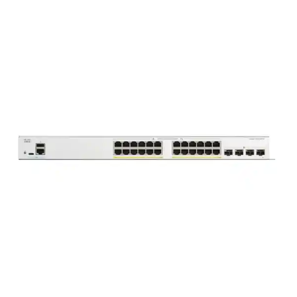
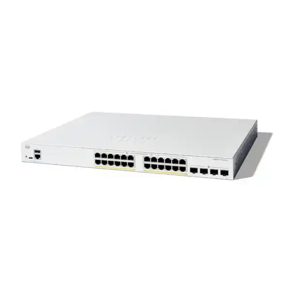
Cisco Catalyst C1300-24FP-4X Network Switch for Dubai and UAE Networks
The Cisco Catalyst C1300-24FP-4X is a managed Layer 3 access switch built for organizations that need a practical combination of Gigabit user connectivity, substantial Power over Ethernet capacity, 10 Gigabit optical uplinks, hardware stacking and business-grade network control. In a single rack-mountable unit, it provides twenty-four 10/100/1000 Ethernet access ports with IEEE 802.3af and 802.3at PoE/PoE+ support, plus four 10 Gigabit SFP+ uplink interfaces. That port mix makes the model a strong fit for UAE branch offices, schools, clinics, hotels, retail sites, warehouses, professional offices and surveillance-heavy environments where endpoint density is moderate but uplink bandwidth, power delivery and segmentation matter.
4 × 10GbE SFP+ uplinks
Layer 3 routing
Front-panel stacking
Direct answer: who should choose the C1300-24FP-4X?
Choose the Cisco Catalyst C1300-24FP-4X when your design requires twenty-four Gigabit powered edge ports, several high-speed fiber or DAC uplinks, managed VLAN segmentation, Layer 3 routing and a PoE budget large enough for a mixed fleet of phones, cameras and wireless access points. The model is particularly attractive when a 24-port switch is the correct physical size but a basic 1G-uplink switch would create an aggregation bottleneck. Four 10G SFP+ interfaces provide enough headroom to build redundant uplinks, connect servers or network appliances, or participate in a stack while preserving useful high-speed connectivity.
It is not the right answer for every design. If most connected devices are Wi-Fi 7 access points needing multigigabit copper or 60W PoE++, a Catalyst 1300X multigigabit SKU is more appropriate. If the site needs only data ports with no endpoint power, a non-PoE model avoids unnecessary cost and heat. If the requirement is a large campus with advanced enterprise automation, modular uplinks or deeper Catalyst feature integration, an enterprise campus switching family may be a better architectural tier. For small and medium business and branch use, however, the C1300-24FP-4X occupies a useful middle ground: substantial PoE, four 10G uplinks, Layer 3 capabilities, stacking and security without forcing the customer into an oversized chassis platform.
Access density
Twenty-four 10/100/1000BASE-T access ports support standard Ethernet endpoints and PoE-powered devices. This density maps naturally to a small wiring closet, department, floor zone or branch.
Uplink headroom
Four 10G SFP+ ports provide a clear upgrade over Gigabit uplink designs, helping protect application performance when many 1G clients converge toward the core, firewall or server environment.
PoE reach
All twenty-four copper access ports support IEEE 802.3af/802.3at PoE. Individual ports can support up to the PoE+ class limit, subject to the switch-wide power budget and endpoint negotiation.
Layer 3 control
Inter-VLAN routing, static and dynamic routing capabilities, DHCP functions and policy-based traffic controls let the switch carry more of the local routing burden inside a branch network.
Hardware architecture and performance
For network planners, the most important performance number is not merely the count of ports but whether the switching fabric can sustain traffic across them without an internal oversubscription penalty. Cisco publishes the C1300-24FP-4X as a wire-speed, nonblocking platform with 128 Gbps of switching capacity and a forwarding rate of approximately 95.23 million packets per second for 64-byte packets. Those values align with the physical port mix: twenty-four 1G access interfaces plus four 10G interfaces create 64 Gbps of one-direction aggregate line rate, and full-duplex switching doubles that figure to 128 Gbps. This is valuable because it means the switch architecture is sized to forward traffic at the advertised interface speeds rather than depending on a smaller internal fabric.
The C1300 family uses a dedicated switching architecture supported by an ARM-based management processor, flash storage and DDR4 system memory. Cisco lists 1 GB SLC flash and 1 GB DDR4 for the standard C1300 range, and the C1300-24FP-4X has a dynamically shared 1.5 MB packet buffer. Packet buffering should not be interpreted as a substitute for capacity planning. In normal enterprise access networks, queuing pressure occurs when many edge interfaces send simultaneously toward a slower or congested destination. The practical defense is therefore a combination of adequate uplink bandwidth, sensible QoS policy, traffic segmentation and congestion-aware design rather than relying only on buffer depth.
The four SFP+ ports create several topology choices. A branch can use two 10G uplinks in a link aggregation group toward a distribution switch and keep two ports available for stack connections or local high-speed devices. A smaller site can allocate one 10G link to the firewall or core, one to a server or storage segment and retain two for growth. Where resiliency is essential, physically diverse fiber paths can be used to different aggregation devices, subject to the design and spanning-tree or link aggregation model. For UAE customers, this flexibility is especially useful in mixed office and building networks where the access closet may serve voice, CCTV, wireless and user data simultaneously and needs more upstream capacity than a single Gigabit link can deliver.
PoE engineering: budget the endpoints, not just the port count
The C1300-24FP-4X supports IEEE 802.3af PoE and IEEE 802.3at PoE+ on all twenty-four 1G copper access ports. Cisco’s current feature table identifies 375 W as power dedicated to PoE for this model, while the ordering-description row for the same SKU describes a 370 W PoE power budget. Because those two figures appear in Cisco’s own current product material, a conservative procurement design should treat 370 W as the planning ceiling unless the exact shipping revision and current Cisco documentation are confirmed during quotation. This conservative approach leaves a small engineering margin and prevents an installation from being designed around the larger figure when a commercial order document uses the lower value.
The key distinction is between per-port capability and total budget. An 802.3at interface may negotiate up to 30 W at the power sourcing equipment side, but twenty-four ports each drawing the maximum would exceed a 370–375 W aggregate budget. Real deployments therefore require an endpoint schedule. Suppose a branch connects twelve IP phones at 7 W each, six fixed cameras at 10 W each, four Wi-Fi 6 access points at 18 W each and two door or IoT devices at 6 W each. The nominal draw is 228 W, leaving substantial headroom for startup behavior, model variation and later additions. If instead the design uses twenty high-power access points close to the 25–30 W range, the aggregate can exceed the switch budget even though every physical port individually supports PoE+.
PoE planning should include at least five data points for every powered endpoint: quantity, IEEE power class, maximum negotiated draw, expected typical draw and business criticality. Critical endpoints such as emergency phones, access-control devices or priority cameras can be given higher PoE priority so that, under an abnormal budget condition, the network sheds lower-priority loads before essential devices. Engineers should also account for cable distance and quality. Standards-compliant copper cabling does not change the switch’s configured PoE allocation, but poor terminations and marginal cable can create voltage drop, link instability or troubleshooting complexity. Cat5e or better structured cabling is appropriate for 1GbE; for new UAE installations, Cat6 or Cat6A is often selected to improve margin and long-term reuse.
For large surveillance or hospitality deployments, compare the PoE design with the UPS and rack power design. A switch able to source more than 300 W to endpoints can draw materially more power during heavy PoE operation than an unpowered access switch. UPS autonomy calculations should therefore use realistic maximum switch draw with PoE enabled, not just the switch’s idle consumption. The objective is end-to-end power continuity: utility input, UPS capacity, PDU rating, switch power supply, PoE budget and endpoint draw must all align. FourTeck can combine switching design with broader UAE infrastructure planning through FourTeck IT Services UAE when the requirement includes rack, structured cabling, UPS, Wi-Fi or multi-site implementation.
10 Gigabit SFP+ uplinks and topology design
The four 10 Gigabit SFP+ uplinks are a defining reason to choose the -4X version rather than a Catalyst 1300 variant with Gigabit SFP uplinks. A 24-port access switch can theoretically receive 24 Gbps of simultaneous ingress traffic from its copper ports. In most office networks that traffic is bursty, so a single 10G uplink may be adequate. In video-heavy, virtualization, backup, imaging or high-density wireless environments, however, multiple 10G paths can materially reduce contention. The correct uplink design depends on the actual traffic pattern and failure requirements, not on port count alone.
SFP+ also gives media flexibility. Short rack-to-rack links may use supported direct attach copper assemblies where appropriate. Building or campus connections usually use optical transceivers selected for fiber type and distance. Multimode optics are common for shorter internal building runs, while single-mode optics suit longer links and provide greater distance flexibility. The optical module at each end must match speed, wavelength, fiber type and link budget. When procuring in Dubai or elsewhere in the UAE, confirm whether the quote includes transceivers and patch leads; switches are frequently supplied without the optics required for the final uplink design.
Link aggregation can combine multiple physical uplinks into a logical channel for added capacity and resiliency when the peer device supports the same arrangement. Engineers should define LACP settings, VLAN trunking, native VLAN policy, allowed VLAN list and spanning-tree behavior before installation. An apparently simple two-cable uplink can create loops or blocked links if the aggregation is configured inconsistently at each end. Likewise, a redundant dual-core topology requires attention to whether the upstream design uses stacking, multi-chassis link aggregation or traditional spanning tree.
The uplink choice also affects firewall positioning. In a conventional branch, local VLANs can be routed on the C1300 and summarized toward the firewall, while internet-bound or policy-sensitive traffic traverses the security appliance. In other designs, all VLAN gateways remain on the firewall for centralized security inspection and the switch operates primarily at Layer 2. Neither is universally correct. The first reduces internal transit load on the firewall and can improve east-west performance; the second centralizes inter-VLAN security policy. FourTeck’s Firewall Dubai practice can align switching and firewall architecture when security zoning, throughput and policy inspection must be sized together.
Layer 2 segmentation, VLANs and traffic separation
A modern access switch is not simply a port concentrator. The C1300 platform supports extensive VLAN functionality for isolating business roles and reducing broadcast domains. Cisco documents support for up to 4094 VLAN identifiers, with a subset reserved for internal use, as well as port-based and IEEE 802.1Q tagged VLANs. It also supports MAC-based, protocol-based and IP subnet-based VLAN classification, management VLANs, private VLAN capabilities, protected-port behavior, guest VLANs, unauthenticated VLANs, dynamic VLAN assignment through RADIUS and 802.1X, voice VLAN functions and auto surveillance VLAN features.
In a typical UAE office, a sensible logical design might separate corporate users, voice, wireless access points, guest Wi-Fi, CCTV, printers, building management and switch management. The value is both operational and security-related. Broadcast and multicast traffic is constrained to the appropriate segment, troubleshooting becomes more deterministic, and security controls can be applied at routed boundaries. Guest devices do not need direct reachability to corporate workstations. Cameras generally do not need unrestricted access to user subnets. Management interfaces can be isolated from normal client networks. Voice can receive differentiated QoS and DHCP options without affecting data endpoints.
Voice VLAN automation is useful for IP telephony deployments because phones can be identified through discovery mechanisms and assigned to a voice-specific VLAN with suitable quality-of-service treatment. This reduces manual port-by-port configuration when a workstation is connected through a phone’s integrated switch port. The design still needs documented trust boundaries: a network should not blindly trust endpoint markings unless the device class and access policy justify it. LLDP-MED and Cisco discovery mechanisms can help communicate capabilities and configuration, but security policy should remain explicit.
For service-provider handoff or more specialized segmentation, the platform includes VLAN translation and Q-in-Q capabilities. Those functions are not required in ordinary office networks, but they can be useful when customer VLAN tags must traverse a provider or shared infrastructure. Engineers should deploy them deliberately because double tagging changes packet overhead and troubleshooting workflows. The broader lesson is that the C1300-24FP-4X can support more sophisticated segmentation than a basic smart switch, making it suitable for organizations that expect the access layer to participate actively in network policy.
Layer 3 routing for branch and SMB networks
Cisco positions the Catalyst 1300 as a Layer 3 switch, and the C1300-24FP-4X belongs to the 10 Gigabit uplink group with an expanded route scale compared with lower-end 1G-uplink models. The platform supports wire-speed IPv4 and IPv6 routing, Layer 3 interfaces on physical ports, link aggregation groups, VLAN interfaces and loopbacks, as well as CIDR. Cisco also lists RIP v2 dynamic routing, policy-based routing, DHCP server functions, Layer 3 DHCP relay and UDP relay. OSPF is reserved for the Catalyst 1300X family, so designs requiring OSPF on the access switch should not assume that capability on this standard C1300 model.
The ability to route between VLAN interfaces can simplify branch networks. Instead of sending every packet between local departments to the firewall or upstream router, the switch can host selected default gateways and route local traffic at switching speed. For example, a server VLAN, user VLAN and printer VLAN can communicate through controlled Layer 3 interfaces while internet-bound traffic follows a default route toward the firewall. This can reduce unnecessary hairpin traffic and keep upstream security devices focused on WAN, VPN and inspection tasks.
Policy-based routing adds another level of control by allowing selected traffic to use a different next hop based on ACL criteria. A branch might direct a specific application subnet toward a dedicated security appliance or WAN router while leaving other traffic on the standard path. PBR should be used sparingly and documented well, because it overrides normal destination-based forwarding logic and can make troubleshooting less intuitive. If the business has multiple internet circuits, SD-WAN, MPLS, cloud security or complex failover rules, it is usually preferable to keep route-policy intelligence on the router or firewall and use the switch for deterministic local routing.
DHCP relay is important when client VLANs obtain addresses from a centralized server located in another subnet. The switch forwards requests across Layer 3 boundaries rather than requiring a DHCP server inside every VLAN. Option 82 and related controls can improve visibility and policy in managed deployments. The main design decision is therefore not whether the switch can route, but which routing responsibilities should live at the access layer. FourTeck engineers can model the traffic flow around security zones, WAN topology and application dependencies so Layer 3 functionality is used where it improves resilience and performance rather than simply because it is available.
Access security: authentication, anti-spoofing and first-hop protection
The access layer is one of the most important enforcement points in a business network because every workstation, phone, access point, camera and IoT device enters through it. The Catalyst 1300 platform includes IEEE 802.1X authentication, port security and web-based authentication options to limit unauthorized access. In an 802.1X design, the switch acts as the authenticator between the endpoint and a RADIUS-based identity service. Policies can assign users or device types to appropriate VLANs, making physical port location less important than verified identity.
Cisco also documents Dynamic ARP Inspection, IP Source Guard and DHCP snooping. Together, these controls help defend against common local-network attacks and configuration mistakes. DHCP snooping builds trust around legitimate address assignment and can block rogue DHCP server behavior. Dynamic ARP Inspection can validate ARP information against trusted bindings, reducing the risk of address spoofing and man-in-the-middle attacks. IP Source Guard can restrict packets whose source addressing does not match expected bindings. These features are most effective when deployed as a coordinated design: trusted uplinks and DHCP paths must be identified correctly, and static endpoints may require explicit handling.
IPv6 should receive equal attention. Many organizations still think of IPv6 as optional, but operating systems and applications often enable it by default. Cisco includes IPv6 First Hop Security functions such as Neighbor Discovery inspection, Router Advertisement guard, DHCPv6 guard and neighbor binding integrity checks. These mechanisms help prevent a rogue host from advertising itself as an IPv6 router or manipulating neighbor discovery. Disabling IPv6 blindly is not always operationally desirable; protecting the protocol at the first hop is a more sustainable strategy where IPv6 is present.
Access Control Lists, storm controls, spanning-tree protections and management-plane restrictions complete the defensive picture. A strong baseline should restrict switch administration to a management subnet, use HTTPS and SSH rather than insecure protocols, integrate RADIUS where practical, log security events to a central collector, synchronize time and document all exceptions. Switch security does not replace a firewall, NAC platform or endpoint security stack, but it meaningfully reduces the attack surface before traffic reaches those systems.
Quality of Service for voice, video and business applications
A converged access switch may carry voice calls, CCTV streams, cloud applications, video meetings, backups and ordinary web traffic over the same physical uplinks. Quality of Service is therefore essential whenever latency-sensitive applications share capacity with bulk transfers. The goal of QoS is not to manufacture bandwidth; it is to classify, mark, queue and schedule traffic so that congestion affects lower-priority flows before it damages delay-sensitive services.
For IP telephony, voice packets are small and sensitive to delay, jitter and loss. A properly designed voice VLAN, DSCP policy and egress queue model can keep calls clear when a workstation begins a large upload. Video conferencing has similar sensitivity but may consume much more bandwidth. Surveillance traffic is usually continuous rather than bursty, so aggregate camera bitrate should be calculated separately and mapped to the uplinks and recorder location. If a network video recorder sits on another floor, for example, the camera VLAN may create steady northbound traffic that must be included in 10G utilization estimates.
QoS trust boundaries matter. A switch can honor markings from known infrastructure such as managed IP phones while remarking or policing untrusted client traffic. Without a trust policy, any endpoint could mark its traffic as high priority and undermine the queues intended for critical applications. Administrators should classify traffic as close to the source as practical, define only a small number of meaningful service classes and test behavior under real congestion. Excessively complicated QoS configurations are difficult to maintain and often provide no benefit.
The C1300-24FP-4X’s four 10G uplinks provide a useful foundation because avoiding congestion is better than managing congestion. QoS then protects application experience during peaks, failures or oversubscribed paths. For a Dubai branch using Microsoft 365, cloud voice, IP cameras and Wi-Fi, the recommended approach is to estimate normal and peak bandwidth per service, reserve uplink headroom, implement simple class-based priorities, and validate the design with monitoring after go-live.
Front-panel stacking and resilient operations
Cisco supports front-panel stacking on the C1300-24FP-4X and other selected Catalyst 1300 models. Up to eight compatible switches can be managed as a single logical stack, providing centralized configuration and a single management address. Cisco also describes hardware failover and the ability to manage hundreds of ports as one system. For growing branches, stacking can reduce administrative overhead because operators work with one logical system rather than configuring each access switch independently.
Stacking design still requires care. The ports used for stack connectivity are valuable high-speed interfaces, so engineers must decide how many are allocated to the stack and how many remain for network uplinks. A ring topology is generally preferred over a simple chain because it provides an alternate path if one stack link fails. Physical cable routing should minimize the chance that one accidental disconnect affects multiple stack paths. When switches serve different racks, verify supported cabling and distance instead of treating front-panel stack ports as arbitrary long-distance interconnects.
Operationally, a stack simplifies firmware coordination, configuration backups and port visibility, but it also creates a shared failure domain. A software defect or configuration mistake can affect the entire stack. Good practice therefore includes maintaining tested configuration backups, using dual images as supported by the platform, scheduling upgrades during controlled maintenance windows and documenting rollback procedures. Critical environments should consider whether two independent switch blocks provide better fault isolation than one larger stack.
Stacking is particularly useful in hotels, schools, clinics and multi-department offices that begin with 24 ports but may grow to 48, 72 or more. It offers a cleaner management model than a collection of standalone switches while preserving the fixed-switch economics of the Catalyst 1300 family. During quotation, FourTeck can confirm stack topology, transceiver or cable requirements, uplink allocation and whether the growth plan should use another C1300-24FP-4X or a higher-density model.
Management, monitoring and lifecycle administration
The Catalyst 1300 series is designed to be manageable by internal IT teams and service partners without requiring a large enterprise management stack. Cisco supports browser-based interfaces, a full CLI text view, SNMP, HTTPS, SSH, RADIUS integration, port mirroring, TFTP-based upgrades, DHCP client functions, SNTP, cable diagnostics, ping, syslog and other familiar operational tools. The series can also be managed with Cisco Business Dashboard, including direct management and an embedded probe model that reduces the need for a separate onsite collector in smaller networks.
For multi-site businesses, central visibility matters more than the convenience of a local GUI. Standardize switch names, site codes, management IP ranges, NTP sources, syslog destinations, SNMP communities or credentials, AAA settings, VLAN IDs and interface descriptions. A documented baseline makes troubleshooting faster because engineers can compare a failing site with a known-good template. It also reduces security drift caused by one-off local changes.
Configuration backups should be treated as production data. Keep copies after commissioning and after major changes, preferably in a controlled repository with version history. If the switch is replaced under warranty or during an incident, a current backup can reduce recovery time dramatically. Firmware should also be managed as a lifecycle process rather than updated randomly. Review Cisco release notes, security advisories and platform compatibility, test where possible, then deploy in a controlled sequence with rollback planning.
Monitoring should include interface utilization, errors, discards, PoE state, temperature, fan status where applicable, stack health, CPU and memory trends, spanning-tree events and link changes. A dashboard showing only whether the switch responds to ping is insufficient. Errors on a camera port may indicate bad cabling; repeated PoE renegotiation may indicate a failing endpoint; high uplink utilization may justify a second 10G link. Proactive monitoring converts raw switch telemetry into capacity and reliability decisions.
Physical specifications, rack integration and UAE environmental planning
The C1300-24FP-4X is a standard rack-mountable switch measuring approximately 444.3 mm wide by 350 mm deep by 43.94 mm high, equivalent to a 1RU chassis, with a published unit weight of about 4.92 kg. The model uses an internal universal 100–240 V AC, 50–60 Hz power supply. Cisco specifies operation from -5°C to 50°C for this model class, with a minimum cold-start ambient of 0°C, and non-condensing operating humidity in the published range. Those environmental limits describe the equipment capability, but UAE deployments should still target a much more controlled rack environment.
Dubai equipment rooms can experience high external temperatures and heavy dust loading if cooling or filtration is poor. A switch should not be designed to run continuously at the top of its ambient specification. Higher temperatures reduce thermal margin and can accelerate component and fan wear. The C1300-24FP-4X includes a fan and Cisco publishes an acoustic figure around 39 dBA at 25°C. Ensure the rack has front-to-back airflow clearance, no blocked ventilation, controlled room temperature and a maintenance plan for dust. Small wall cabinets installed above ceilings or in utility rooms deserve particular scrutiny because local heat can be significantly higher than the main office temperature.
Rack depth is another practical detail. A 350 mm chassis may fit many cabinets, but power connectors, fiber bends, patch panels and rear clearance add to the usable depth requirement. Shallow wall cabinets can become crowded once vertical cable managers and UPS equipment are installed. Confirm the internal cabinet depth rather than relying on the external rack dimension. Front patching should maintain bend radius for fiber jumpers and avoid placing mechanical stress on SFP+ transceivers.
Power design should include a UPS sized for the switch plus its PoE endpoints. When the switch powers cameras, phones and access points, the UPS effectively becomes the backup source for all those devices. This is an advantage because one centralized UPS can preserve network services during an outage, but it increases the required VA and watt capacity. FourTeck’s Server Dubai infrastructure team can coordinate rack, UPS and server-room requirements where the switch forms part of a broader equipment-room deployment.
Deployment scenario 1: secure branch office with voice and Wi-Fi
Consider a 60-person Dubai branch with twenty desk phones, twelve fixed workstations, four wireless access points, two printers, several meeting-room devices and a small server or appliance footprint. The C1300-24FP-4X can serve one access zone while a second switch handles remaining wired endpoints. Phones and access points receive power directly from PoE+, reducing local adapters and allowing the network UPS to keep communications online during short utility interruptions.
The branch can define corporate, voice, guest, infrastructure, printer and management VLANs. Phones use the voice VLAN with appropriate QoS. Access points carry tagged corporate and guest WLAN segments. The guest VLAN is routed toward the firewall with no direct access to corporate resources. Switch management is limited to the IT subnet, authenticated through centralized credentials where available. DHCP snooping and ARP inspection can be enabled on user-facing VLANs after trust boundaries are validated.
Two 10G SFP+ links can form a resilient aggregated uplink to the local core or distribution pair. If the branch is smaller and uses a single firewall as its aggregation point, one 10G path may be enough initially, leaving extra SFP+ ports for a server, future secondary path or stack link. Inter-VLAN routing may reside on the switch for high-volume local services, or on the firewall where policy inspection between departments is required.
The design becomes easy to operate when interface descriptions identify the room or endpoint, VLAN assignments follow a standard template and PoE priorities protect phones and infrastructure. Monitoring should alert on uplink saturation, PoE budget thresholds and access-point port errors. The C1300-24FP-4X works well here because the branch needs more than an unmanaged or web-smart switch but does not require a large modular campus platform.
Deployment scenario 2: IP surveillance and access control
Surveillance is a natural use case for a high-PoE 24-port switch because cameras often need both network and power in locations where electrical sockets are inconvenient. A warehouse might connect eighteen fixed PoE cameras, two PTZ units, access-control panels and a local recorder or uplink toward a centralized NVR. The engineering task is to calculate not only port count but camera power, video bitrate, retention architecture and failure impact.
Each camera model should be checked for maximum PoE draw, especially units with heaters, infrared illuminators, motorized lenses or pan-tilt-zoom mechanisms. A camera that averages 9 W may draw much more during startup or when accessories activate. The 370–375 W class aggregate budget of the C1300-24FP-4X is generous for many fixed-camera deployments, but an endpoint table is still required. High-power devices should not be estimated from typical consumption alone.
Traffic calculations are equally important. Twenty cameras averaging 8 Mbps create about 160 Mbps of continuous video before protocol overhead, well within a 1G link, but higher-resolution, high-frame-rate or multi-stream cameras can produce much more. If the recorder is remote and several camera switches converge toward the same aggregation point, a 10G uplink provides strong headroom. Multicast, where used, should be controlled with IGMP snooping so video streams do not flood ports that did not request them.
The camera VLAN should be isolated from normal users, with only necessary routes toward recorders, management stations, DNS, NTP or cloud services. Port security, DHCP controls and management-plane ACLs can reduce exposure. A UPS sized for the full switch and camera load can keep surveillance active during short outages. The result is a cleaner, more resilient design than powering every camera from a local adapter.
Deployment scenario 3: hospitality, education and multi-service floors
Hotels, schools and mixed-use facilities frequently combine multiple low- and medium-bandwidth devices on the same access layer: phones, access points, cameras, digital signage, point-of-sale terminals, controllers and staff workstations. The challenge is not raw packet forwarding but policy separation and operational consistency. The C1300-24FP-4X provides enough VLAN, PoE, uplink and Layer 3 capability to build a standardized floor switch template across many closets.
A hotel floor might use separate VLANs for guest Wi-Fi access points, staff devices, IP phones, CCTV and building services. A school can isolate teaching devices, administration, voice, cameras and wireless infrastructure. A clinic can separate clinical systems, staff, guest access, voice and security endpoints. Those logical divisions reduce the risk that a compromised or misconfigured device reaches unrelated systems. Private VLAN or protected-port functions may further isolate peer endpoints where client-to-client communication is unnecessary.
Standardizing the configuration across floors improves support. Port ranges can be reserved for access points or cameras, uplink trunks can use a consistent allowed-VLAN policy, switch management addresses can follow a predictable scheme and monitoring can label devices by building and floor. Stacking may be used in larger closets where two or more switches are installed together, but independent units with redundant uplinks can be preferable when fault isolation is a priority.
The four 10G interfaces are especially useful when multiple services converge. Even if each floor currently generates only a few hundred megabits per second, a 10G backbone provides growth capacity for new wireless generations, higher-resolution cameras and cloud application usage. In new UAE construction, it is often more economical to install fiber and 10G-capable aggregation from the start than to revisit riser cabling and optics later.
Multicast, discovery and service-aware access
Networks carrying IPTV, surveillance, conferencing or service-discovery traffic can suffer unnecessary load when multicast is handled like broadcast. Cisco documents IGMP snooping support across the Catalyst 1300 platform, including versions 1, 2 and 3, with a larger multicast group scale on the 10 Gigabit SKU class that includes the C1300-24FP-4X. IGMP snooping allows the switch to forward multicast streams only toward ports that have joined the relevant group, rather than flooding every access interface.
This is valuable in hospitality IPTV and camera environments where the same switch may carry many streams. Multicast VLAN Registration can also support architectures where a multicast source VLAN is shared while subscribers remain in separate VLANs. These features should be paired with a correctly designed querier and routed multicast architecture where needed. Without a querier, group membership can age unpredictably in some Layer 2 designs.
LLDP and LLDP-MED help devices exchange identity and capability information. IP phones can learn voice VLAN and related parameters; network administrators can see neighboring device information for troubleshooting. Cisco Discovery Protocol provides similar visibility in Cisco environments. Discovery protocols are operationally useful, but exposure should be considered on untrusted ports. The switch configuration should disclose only what is required and follow the organization’s security baseline.
These functions illustrate why a managed access platform is valuable even in a modest branch. The network can identify device classes, constrain multicast, automate voice behavior, collect neighbor data and maintain predictable forwarding. That reduces the amount of manual troubleshooting compared with an unmanaged switch where every port behaves identically and visibility is limited.
Sizing method: a disciplined way to decide whether this model fits
A reliable switch selection can be made with a five-part sizing model. First, count physical endpoints and add growth. If the site has exactly twenty-four known devices today, a 24-port switch leaves no room for a new access point, temporary troubleshooting connection or device replacement. Many projects therefore target 15–25 percent spare port capacity unless rack space or cost dictates otherwise. Second, identify which endpoints need PoE and record maximum power class. Third, calculate uplink traffic. Fourth, define logical and security features. Fifth, confirm environmental, support and lifecycle requirements.
For port capacity, do not count only users. Include wireless access points, cameras, phones, printers, biometric readers, door controllers, building-management gateways, conferencing endpoints, servers, hypervisors, storage, management ports and spare interfaces. If phones pass through to PCs, one physical switch port may serve two logical devices, but it still creates voice and data traffic. If access points broadcast multiple SSIDs, one physical interface may carry several VLANs.
For PoE, sum maximum expected power and add margin. A practical branch design might reserve 15–20 percent of the available PoE budget for variation and expansion. The exact margin depends on how predictable the endpoint fleet is. A standardized phone deployment is easy to estimate; a mixed IoT environment is not. If the result approaches the 370 W conservative planning ceiling, consider redistributing devices or selecting a higher-budget platform.
For uplinks, estimate sustained and peak traffic separately. User web traffic is bursty. Backups, software distribution and camera streams can be sustained. Wi-Fi traffic may grow quickly after an access-point refresh. If two 10G links are used as an LAG, remember that a single flow generally stays on one member based on a hashing algorithm; aggregation increases total capacity across many flows rather than creating one 20G pipe for every individual session.
Finally, map the required protocols. If the design needs 802.1X, dynamic VLANs, DHCP snooping, Layer 3 interfaces, RIP, PBR, stacking and 10G SFP+, the C1300-24FP-4X is a strong fit. If it needs OSPF, multigigabit copper or 60W PoE++, move to an appropriate C1300X model. If it needs sophisticated campus automation or larger scale, evaluate a higher Catalyst family. This method prevents product selection from being driven by a single headline such as port count.
Technical specification summary
| Model | Cisco Catalyst C1300-24FP-4X |
| Access ports | 24 × 10/100/1000BASE-T Gigabit Ethernet |
| Power over Ethernet | IEEE 802.3af PoE and IEEE 802.3at PoE+ on 24 access ports; up to 30 W class per port subject to aggregate budget |
| PoE budget note | Cisco technical feature table lists 375 W dedicated to PoE; ordering description lists 370 W. FourTeck recommends conservative 370 W project sizing unless current shipping documentation confirms otherwise. |
| Uplinks | 4 × 10 Gigabit SFP+ |
| Switching capacity | 128 Gbps, wire-speed and nonblocking |
| Forwarding rate | Approximately 95.23 Mpps for 64-byte packets |
| Packet buffer | 1.5 MB dynamically shared |
| System memory | 1 GB DDR4 for standard C1300 platform |
| Flash | 1 GB SLC |
| Layer 3 | IPv4/IPv6 routing, static and dynamic capabilities including RIP v2, PBR, DHCP server/relay; OSPF is a C1300X-only feature |
| Stacking | Front-panel hardware stacking supported; up to 8 compatible switches in a stack |
| Management | Web UI, CLI, SNMP, SSH, HTTPS, RADIUS, Cisco Business Dashboard support and standard diagnostics |
| Dimensions | Approximately 444.3 × 350 × 43.94 mm |
| Weight | Approximately 4.92 kg |
| Power input | 100–240 V AC, 50–60 Hz internal universal supply |
| Form factor | Rack-mountable, approximately 1RU |
Choosing optics, fiber and copper correctly
A switch quotation is incomplete if the uplink media is not defined. The C1300-24FP-4X provides SFP+ cages, but the correct transceiver depends on distance, fiber plant and peer interface. For a short connection inside the same rack or adjacent rack, a supported direct-attach copper cable may be cost-effective. For building links, SFP+ optical modules are typical. The transceiver type must match the installed fiber: multimode optics require suitable multimode fiber, while single-mode optics require single-mode fiber. Connector type, polarity and patch-panel presentation must also match.
Existing buildings often have unknown fiber history. Before ordering optics, confirm whether the link is OM2, OM3, OM4 or single-mode, verify strand count and test continuity and loss. A label on the patch panel is helpful but not sufficient evidence for a critical uplink. If the design requires two redundant links, confirm that they use genuinely diverse fiber paths rather than two strands in the same vulnerable cable route.
Copper access cabling should be Cat5e or better for Gigabit Ethernet. New projects generally benefit from Cat6 or Cat6A because the cabling is likely to outlive the switch and may later serve multigigabit or 10G devices depending on distance and installation quality. PoE also makes conductor quality important. Avoid noncompliant copper-clad-aluminum cable and poorly terminated patch cords, especially with higher-power endpoints. Heat accumulation in large PoE cable bundles should be considered in structured cabling design.
FourTeck can provide the switch as part of a broader UAE network bill of materials through FourTeck UAE, including compatible optics, patch leads, rack accessories and implementation services. The quotation should state every optical part explicitly so the installation team is not left with a switch and no working uplinks.
Redundancy, spanning tree and failure-domain planning
Redundancy is beneficial only when the control plane understands the redundant paths. Connecting two uplinks from an access switch to the same or different upstream switches can create a Layer 2 loop if the topology is not configured correctly. Spanning Tree Protocol provides loop prevention by selecting active paths and blocking redundant ones, while link aggregation allows compatible parallel links to operate as one logical bundle. The right choice depends on whether the upstream devices form a single logical system and whether cross-device aggregation is supported.
Access ports should use edge or PortFast-style behavior where appropriate so end devices do not wait through unnecessary topology transitions. At the same time, BPDU protection can prevent an accidental downstream switch from becoming part of the spanning-tree topology. Root-guard and loop-protection features can help enforce intended topology boundaries. These controls need a documented design because enabling them blindly on trunks or legitimate infrastructure links can cause outages.
Redundancy should also be considered above and below the switch. A dual-uplink access switch still depends on one internal power supply, one rack power path and potentially one UPS. If a site cannot tolerate loss of all endpoints connected to the unit, distribute critical devices across two switches powered by independent protected circuits where feasible. Similarly, a stack improves management and can provide path resiliency, but it can also create a common software or configuration domain.
The best architecture starts by defining failure scenarios: loss of one uplink, one core switch, one access switch, one power circuit, one UPS, one fiber path or one configuration domain. For each scenario, document which users and services should remain available. This approach turns redundancy from a marketing checkbox into measurable business continuity.
Procurement considerations for Dubai and the UAE
Enterprise switch procurement should confirm more than the model number. The quotation should identify the exact orderable SKU, warranty or support entitlement, included power cord type, rack-mount accessories, software image, transceivers, stacking components and any implementation scope. If the switch is replacing an older model, confirm physical depth, rack power and optic compatibility before the maintenance window. A product that appears equivalent on paper can create last-minute delays when the uplink media or power connector differs from the installed environment.
Lead time and lifecycle status also matter. Network hardware may be sourced from regional distribution or project inventory, and the delivery schedule can change with quantity and support requirements. Organizations planning branch rollouts should standardize a bill of materials and order spare units or optics where downtime cost justifies it. Maintaining one compatible cold spare can be more valuable than paying for emergency logistics after a failure.
For UAE projects, deployment documentation should record rack location, switch serial number, hostname, management IP, firmware release, stack role, uplink transceiver serials, VLAN assignment, PoE endpoint inventory and support expiry. This information simplifies audit, incident response and future refresh planning. It is especially important in multi-site retail, hospitality and education environments where many similar closets exist.
Customers requiring cross-border deployment can also coordinate broader sourcing and standards through FourTeck Global. For this page, the commercial target is Dubai and the United Arab Emirates, but the same disciplined approach to BOM control, optics, support and configuration standardization applies to regional rollouts.
Migration from an older access switch
Replacing an existing switch is an opportunity to clean up network design rather than simply copying every legacy command. Start by exporting the current configuration and producing a port map that identifies connected devices, VLANs, trunks, PoE endpoints, static bindings and special security settings. Compare each requirement with the C1300 feature set. Unsupported or obsolete commands should be redesigned, not mechanically translated.
Next, validate optics and cabling. An older switch may use 1G SFP uplinks; the C1300-24FP-4X’s SFP+ cages support the new 10G design, but the peer device and optical modules must match the intended speed. If the migration keeps 1G optics temporarily, confirm explicit compatibility in current Cisco documentation rather than assuming every SFP module will operate in every SFP+ port. A staged upgrade may preserve connectivity while the core is refreshed, but it should be planned as a supported configuration.
PoE migration requires similar discipline. Record the current powered devices and their measured or negotiated draw. Some legacy endpoints may use pre-standard Cisco PoE behavior, while newer devices use 802.3af or 802.3at. The Catalyst 1300 platform supports Cisco legacy PoE in addition to standards-based PoE on the relevant models, but endpoint testing is still advisable for critical devices. Schedule a maintenance window that allows enough time to verify phones, cameras and access points after the cutover.
Finally, test the network as users experience it: DHCP, DNS, voice registration, Wi-Fi association, internet access, printing, camera recording, server reachability and management access. Verify redundant uplinks and failover deliberately. A migration is complete only when operational monitoring, backups and documentation have also been updated.
Operational baseline after installation
A production-ready switch should leave commissioning with a defined baseline. Change the default management credentials, use role-appropriate administrator accounts, disable insecure management protocols where they are not required, enable SSH and HTTPS, restrict management access to dedicated subnets, configure NTP, send syslog to a central collector and back up the running and startup configuration. If RADIUS or another centralized AAA service is available, integrate it while preserving a controlled emergency-access method.
Interface configuration should be explicit. User ports receive the correct access VLAN, edge behavior and endpoint security. Phone ports receive voice settings and QoS treatment. Access-point ports use the intended native and tagged VLAN model. Uplinks are documented as trunks with a restricted allowed VLAN list rather than carrying every VLAN by default. Unused interfaces can be administratively disabled or placed in an unused quarantine VLAN according to policy.
PoE monitoring deserves its own baseline. Capture the normal switch-wide power draw after all endpoints are connected, note high-power ports and define an alert threshold below the maximum budget. This gives operators a reference point for future changes. If the normal load is already near the planning ceiling on day one, the design lacks expansion margin and should be revisited before more devices are added.
Performance validation should capture uplink utilization during a representative business period, not only during an empty maintenance window. Look for CRC errors, duplex or negotiation anomalies, drops, queue discards and unexpected topology changes. A clean commissioning report becomes evidence that later problems are environmental or change-related rather than present from initial installation.
Decision recap: where the C1300-24FP-4X is strongest
Best fit
Twenty-four-port branches that need substantial PoE+, 10G fiber uplinks, VLAN segmentation, Layer 3 routing and a manageable path to stacking.
Performance fit
128 Gbps switching capacity and four 10G SFP+ links make the platform suitable for converged voice, Wi-Fi, surveillance and user-access traffic.
Power fit
All 24 access ports support PoE+, with project sizing recommended against a conservative 370 W aggregate planning budget.
When to choose another model
Move to C1300X when multigigabit copper, PoE++ or OSPF is required; use a non-PoE variant when endpoint power is unnecessary.
The model’s strongest value is balance. It is not optimized around one extreme specification; instead it combines a useful 24-port footprint, high PoE capacity, multiple 10G uplinks, Layer 3 functionality, robust access security and practical management. That combination fits many real UAE branch designs better than either a basic smart switch or an oversized campus chassis.
Quotation input checklist
For an accurate Cisco Catalyst C1300-24FP-4X quotation and deployment plan, provide the following project information. A complete input set allows the switch, optics, rack power and services to be sized together rather than quoted as disconnected parts.
1. Port schedule
Number of PCs, phones, access points, cameras, printers, servers, controllers and spare ports required now and within the next 24–36 months.
2. PoE endpoint list
Exact powered-device models, quantities and maximum PoE draw. Identify critical devices that should receive priority during a power-budget event.
3. Uplink media
Distance to the core or firewall, fiber type, connector presentation, peer switch model and whether one or two 10G paths are required.
4. Logical design
Required VLANs, routing location, DHCP design, voice VLAN, guest network, CCTV isolation, management subnet and authentication method.
5. Resiliency
Stacking requirement, redundant uplinks, dual upstream switches, UPS runtime and acceptable outage scope if one access switch fails.
6. Commercial scope
Quantity, delivery location in the UAE, required support, installation window, rack and cabling scope, configuration services and documentation expectations.
Consultation panel: turn the switch SKU into a complete working design
A production network requires more than the switch itself. FourTeck can help map endpoint counts to PoE budget, select SFP+ optics, define VLAN and routing architecture, coordinate firewall policy, size UPS capacity, document uplinks and build a commissioning checklist. This is especially useful when the C1300-24FP-4X will support mixed services such as IP telephony, Wi-Fi and CCTV, because each service introduces its own power, traffic and security requirements.
For a simple supply-only requirement, provide quantity and delivery location. For a deployment quote, include the port schedule, powered-device models, fiber distance, existing core or firewall model and required VLANs. For a migration, provide the old switch configuration or a sanitized port/VLAN export so the new design can preserve valid requirements while removing legacy settings that no longer make sense.
The result should be a bill of materials that is explicit about the Cisco Catalyst C1300-24FP-4X, compatible uplink components, rack accessories, support and implementation scope. That level of detail prevents the common procurement problem of receiving the correct switch but missing the optics, stack links, patching or design work needed to place it into service.
Final recommendation for UAE buyers
The Cisco Catalyst C1300-24FP-4X is a strong access-layer choice for organizations that want twenty-four standards-based PoE+ Gigabit ports without sacrificing uplink performance or Layer 3 functionality. Its four 10G SFP+ interfaces provide meaningful headroom for aggregation and growth, while front-panel stacking offers a clean expansion path when one 24-port switch becomes two or more. Access security, VLAN flexibility, IPv4/IPv6 routing and centralized management features make it suitable for professional business networks rather than basic connectivity-only installations.
The two design checks that matter most are PoE and topology. Confirm endpoint power against a conservative 370 W project budget, and decide how the four SFP+ ports will be divided between uplinks, stack links and local high-speed connections. If those two elements are designed correctly, the platform can serve as a stable foundation for phones, cameras, access points and user devices across a wide range of Dubai and UAE deployments.
For buyers comparing multiple Cisco models, provide the endpoint count, PoE requirements, uplink distance and routing needs. FourTeck can then determine whether the C1300-24FP-4X is the correct fit or whether a lower-power, higher-density, multigigabit or C1300X alternative would deliver better lifecycle value.

Reviews
There are no reviews yet.