
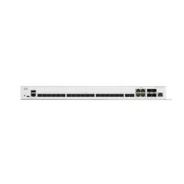
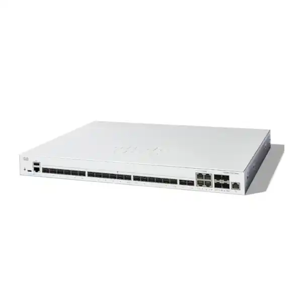
Cisco Catalyst C1300-24XS Network Switch in UAE
The Cisco Catalyst C1300-24XS is a high-density 10 Gigabit Ethernet managed switch for organizations that need fiber-rich aggregation, server connectivity, resilient branch switching and advanced Layer 3 control without moving immediately to a larger campus switching architecture. Its interface mix is especially useful where the distribution layer must terminate multiple SFP+ links while preserving the flexibility to connect selected 10GBASE-T devices through combo interfaces.
FourTeck positions this model for UAE projects where predictable wire-speed forwarding, manageable growth, secure segmentation and practical deployment economics matter more than oversized chassis platforms. It is suitable for office headquarters, schools, healthcare branches, hospitality IT rooms, retail back offices, engineering firms, warehouses, server rooms and distributed business networks that require a compact 1U 10GbE switching layer.
At-a-glance platform facts
Fiber-first access
Twenty dedicated SFP+ ports make the C1300-24XS a natural aggregation choice for server, firewall, storage, building and inter-switch fiber links that need 10GbE bandwidth.
Flexible combo edge
Four additional 10G combo interfaces let designers choose either copper or SFP+ presentation on a per-port basis, useful when appliance and server media types differ.
Layer 3 control
Wire-speed IPv4 and IPv6 routing, RIP v2, static routes, policy-based routing and Layer 3 interfaces can keep east-west traffic local instead of hairpinning through a firewall.
Stack-ready growth
Front-panel stacking supports up to eight compatible switches in the same C1300 family group, enabling unified control, cross-stack LAG and simpler operational scaling.
What is the Cisco Catalyst C1300-24XS?
The Cisco Catalyst C1300-24XS is a fixed, managed Layer 3 Ethernet switch in Cisco’s Catalyst 1300 family. It is not a conventional 24-port Gigabit access switch. The product is built around 10 Gigabit Ethernet interfaces, giving it a different role in network design. Its most common position is in an aggregation, compact core, high-speed distribution or server-access layer where many uplinks converge and where several network zones need to communicate at low latency. That distinction matters when planning a bill of materials. A buyer looking for desktop user access, PoE phones or direct Wi-Fi access-point powering normally needs a different Catalyst 1300 model. A buyer looking to collect 10GbE fiber trunks, server NIC links and high-capacity appliance connections is much closer to the intended use case for the C1300-24XS.
The switch exposes twenty dedicated 10G SFP+ interfaces and four additional 10G copper/SFP+ combo interfaces. A combo interface represents one logical port with two possible physical media presentations; only one side of each combo pair is active at a time. That lets a project mix optical and copper connectivity without dedicating an entire switch to one media type. A separate Gigabit Ethernet out-of-band management port provides a management path that can be isolated from production forwarding. The front panel also includes console connectivity, including a standard RJ-45 console interface and USB Type-C functionality for console and file or image handling.
For UAE enterprises, this architecture can simplify a rack where several floors, buildings, network closets or virtualized servers already operate at 10GbE. Instead of consuming multiple uplink slots across lower-speed access switches, the C1300-24XS can become a dedicated high-speed concentration point. It can also provide local Layer 3 boundaries between VLANs, reducing unnecessary dependency on an edge security appliance for trusted east-west flows when policy allows. That does not replace the role of a firewall. It simply allows network designers to separate routing responsibilities from security inspection responsibilities in a more deliberate way.
The platform uses Cisco’s managed switching software with browser-based configuration, command-line access, SNMP and Cisco Business management capabilities. It sits in the practical middle ground between basic web-managed switching and large enterprise campus platforms: more routing, resiliency and segmentation depth than entry switching, but with a simplified deployment and operational model aimed at small and medium enterprises, branch offices and growing networks. For organizations standardizing on Cisco while keeping procurement and administration proportionate to site size, that positioning is often the key reason to evaluate the C1300-24XS.
C1300-24XS port architecture and physical interface planning
The twenty dedicated SFP+ ports are the defining characteristic of the model. SFP+ makes it possible to choose an optical transceiver according to the fiber plant, distance and wavelength requirements rather than being locked into a fixed copper PHY. That is valuable in UAE installations because structured cabling conditions vary widely between new offices, multi-floor towers, industrial facilities, campuses and retrofitted buildings. A short in-rack server connection may use direct-attach cabling where supported by the deployment design, while a different port may use multimode fiber to another room and another may use single-mode fiber across a campus. The switch becomes a common forwarding platform while the transceiver selection adapts each physical path.
The four combo ports deserve special attention during design. They do not create eight simultaneous 10G data interfaces. Each combo port provides alternative copper and SFP+ media for the same logical interface. The project engineer should therefore count the C1300-24XS as twenty-four operational 10GbE data ports, not twenty-eight. This matters when calculating oversubscription, rack port density, spare capacity and future expansion. If a design requires twenty-four optical connections, the four combo interfaces can be used on their SFP+ side. If several appliances expose only 10GBASE-T, some combo interfaces can instead be used on their copper side.
Because the product does not provide access-port PoE, it should not be purchased with the expectation that it will directly power IP phones, surveillance cameras or wireless access points. Those endpoints are typically connected to PoE-capable access switches, while the C1300-24XS aggregates those switches over 10GbE. This division of roles often produces a cleaner network hierarchy: endpoint switches focus on edge power and user access, while the 24XS focuses on high-bandwidth transit, routing, redundancy and server-side connectivity.
The dedicated management interface can be incorporated into a separate management VLAN or physically isolated operations network. In environments with stronger operational controls, that allows administrators to reach the switch without sharing the same path as production application traffic. For managed services, remote support and sites where troubleshooting access must remain available during a data-plane change, this separation can significantly improve maintainability.
Switching performance: 480 Gbps fabric and 357.14 mpps forwarding
Cisco specifies the C1300-24XS with 480 Gbps of switching capacity and 357.14 million packets per second of forwarding capacity for 64-byte packets. The design is described as wire-speed and nonblocking. In practical terms, this means the switching fabric is sized for simultaneous full-duplex traffic across the model’s 10GbE data interfaces without requiring a deliberate internal oversubscription ratio. For a compact aggregation switch, that characteristic is important because bursts may arrive concurrently from several access closets, hypervisor hosts, backup targets and security appliances.
A 480 Gbps switching-capacity figure is consistent with twenty-four 10GbE ports counted in both transmit and receive directions: 24 × 10 Gbps × 2. It does not mean every application automatically achieves 480 Gbps of usable throughput. Real application performance depends on frame size, protocol overhead, host NIC behavior, optical quality, routing or ACL configuration, upstream bottlenecks and server performance. The number is best understood as the internal forwarding envelope of the switch rather than as an end-to-end application benchmark.
The forwarding-rate figure is particularly relevant for workloads with small packets. Storage replication, virtualization, voice signaling, telemetry, east-west application calls and firewall transit can generate very different packet-size distributions. A switch that appears adequate only from a raw gigabit-per-second number may still become constrained by packet-processing limits when packet sizes fall. The 357.14 mpps specification gives network architects a separate indicator for packet-rate sizing and confirms that the platform is intended for high-throughput 10GbE roles rather than merely providing a handful of fast uplinks on a Gigabit access switch.
The C1300-24XS also includes an 8 MB aggregate packet buffer that is dynamically shared across the ports. Buffering is not a substitute for sound capacity planning, but it helps absorb short-lived congestion when traffic arriving on several 10GbE interfaces converges toward a smaller number of egress links. This can happen when multiple access stacks simultaneously send traffic to a firewall pair, when backup jobs start together, or when several servers burst toward a storage target. Engineers should still use QoS, appropriate LAG sizing and careful uplink planning rather than relying on buffer depth alone.
For latency-sensitive deployments, the correct sizing question is therefore not simply whether the switch is ’10 Gigabit.’ The engineer should map source and destination traffic, identify convergence points, estimate steady-state and burst traffic, decide whether flows remain within the switch or leave through a firewall, and then calculate whether individual uplinks or LAGs are the real constraint. The C1300-24XS provides a strong forwarding foundation, but the surrounding architecture determines how much of that capacity becomes useful business performance.
Front-panel stacking for scalable, resilient operations
The Catalyst 1300 family supports front-panel stacking for up to eight switches, and the C1300-24XS is listed in the 10 Gigabit Ethernet stacking family. A stack operates as a unified system rather than as a collection of independently managed switches. Cisco describes unified data, control and management planes, with a single management IP address for the stack. This can materially reduce operational complexity when a site grows from one high-speed switch to several because VLAN changes, monitoring, troubleshooting and many policy operations can be handled at the stack level.
Stack compatibility must be planned carefully. The C1300 family is divided into compatible stacking groups, and products from different family groups cannot simply be mixed into one hardware stack. The C1300-24XS belongs to the same listed family group as models including the C1300-12XT-2X, C1300-12XS, C1300-16XTS, C1300-24XT and C1300-24XTS. This matters for phased procurement. If an organization expects to add capacity later, it should decide whether future expansion is likely to require more fiber, more copper or a balanced media mix and select compatible members accordingly.
A primary technical advantage of stacking is cross-stack link aggregation. Instead of terminating both members of a redundant LAG on a single physical switch, engineers can distribute the links across stack members where the topology and connected device support it. This reduces the impact of an individual switch failure and helps create more resilient connections to firewalls, servers and downstream switching layers. The platform also supports rapid stack failover, active and standby stack control, hot swap of stack units, auto-numbering and ring or chain stack arrangements.
Stacking does not remove the need for a failure-domain design. A rack still depends on power, cooling, fiber paths and upstream devices. For critical sites, FourTeck recommends evaluating dual power circuits where available, separate upstream firewall or router paths, physically diverse fibers for cross-stack LAGs and configuration backup procedures. A stack should simplify control and improve device-level resilience, not create a false assumption that every failure mode has been eliminated.
In a UAE branch or head-office environment, the operational benefit can be substantial. A small IT team can manage a growing 10GbE aggregation layer from one logical system rather than maintaining separate device-level configuration on each switch. This is particularly attractive for organizations with lean local staffing, centralized IT administration or managed-service support. For implementation assistance, FourTeck can combine switching work with broader UAE IT services covering rack readiness, cabling, migration planning and network documentation.
Layer 2 switching: VLAN, loop prevention, LAG and multicast control
The Layer 2 feature set is broad enough for business networks that need more than simple VLAN separation. The Catalyst 1300 series supports up to 4094 VLAN identifiers, with a portion reserved for internal use, and includes port-based, 802.1Q tagged, MAC-based, protocol-based and IP-subnet-based VLAN mechanisms. It also supports management VLANs, private VLAN behavior, guest and unauthenticated VLANs, RADIUS-driven dynamic VLAN assignment, voice VLAN functions and other segmentation tools. That range is useful when one aggregation switch must service several operational zones such as corporate users, servers, voice, guest access, CCTV, building systems and management infrastructure.
Spanning-tree support includes classic STP, Rapid Spanning Tree and Multiple Spanning Tree. Cisco also specifies PVST+ and Rapid PVST+ support. In a network with redundant Layer 2 paths, the correct spanning-tree mode should be chosen deliberately rather than left as an afterthought. Rapid convergence can reduce disruption during a link failure, while MST can help group VLANs into a manageable number of spanning-tree instances. The best choice depends on the wider Cisco and third-party switching environment and on whether the design intends to keep Layer 2 domains local or stretch them across multiple closets.
Link aggregation uses IEEE 802.3ad LACP. The platform supports up to eight aggregation groups and up to eight ports per group. LAGs are essential when a single 10GbE connection is insufficient or when redundancy is required between switching layers. Two, four or more physical links can be bundled into one logical connection, subject to the capabilities and configuration of the peer device. Traffic distribution across member links is flow-based, so one very large flow does not necessarily consume the sum of all link capacities; multiple concurrent flows are where LAG capacity becomes most effective.
For video distribution, monitoring platforms and other multicast-heavy workloads, IGMP-related capabilities help avoid flooding multicast traffic to every interface. IGMP snooping, querier and proxy functions can be used according to topology. This is relevant in hospitality IPTV, surveillance, audio-visual networks and monitoring systems where uncontrolled multicast can consume significant bandwidth and create difficult-to-diagnose performance problems.
The switch also supports features such as UDLD for detecting unidirectional links, loopback detection and multiple guard mechanisms around spanning tree. These become especially important in fiber-rich networks because a fiber path can fail asymmetrically or be mispatched in a way that is not always obvious from a basic link-up indicator. Layer 2 protection features should be treated as part of the baseline configuration template rather than enabled only after an incident.
A good deployment standard separates user-facing VLAN design from infrastructure-control design. Native VLAN handling, trunk allowed lists, management VLANs, edge-port settings, root-bridge placement and LAG parameters should be documented before cutover. This reduces the risk that a high-capacity 10GbE switch unintentionally extends broadcast domains or creates a loop at greater speed. The C1300-24XS has the tools needed for disciplined Layer 2 architecture; the implementation quality determines whether those tools deliver predictable operations.
Advanced Layer 3 routing without overbuying a chassis core
The C1300-24XS can perform wire-speed IPv4 and IPv6 routing, allowing it to operate as more than a Layer 2 aggregation bridge. Layer 3 interfaces can be configured on physical ports, LAGs, VLAN interfaces or loopback interfaces. For a branch office or compact campus, this means inter-VLAN traffic can be routed locally when security policy permits, rather than forcing every trusted flow through a firewall or external router. The result can be lower latency, reduced firewall interface utilization and a clearer division between internal routing and security enforcement.
Cisco’s current specification for the 10 Gigabit Ethernet C1300 models states support for up to 7168 combined dynamic and static IPv4 routes and up to 256 IP interfaces. Those are meaningful numbers for SMB and branch-scale routing. They allow the switch to support many routed VLANs, point-to-point segments, summarized internal prefixes and connected networks without being limited to a very small static-routing table. Actual design should still remain simple enough for the operating team to understand and troubleshoot.
Dynamic routing on the C1300 includes RIP version 2. Policy-Based Routing is also supported, using IPv4 or IPv6 ACL criteria to direct matching traffic toward a different next hop. PBR can be useful when a site has multiple security zones or multiple WAN and firewall paths and selected traffic needs deterministic steering. It should be used carefully, because policy routing can make packet paths less obvious than conventional destination-based routing. Good documentation and route-monitoring practices are essential.
OSPFv2 and OSPFv3 are specified for Catalyst 1300X models only, not for the C1300-24XS. If OSPF is a mandatory routing requirement, the design should move to an appropriate C1300X or another Cisco platform rather than assuming feature parity across the 1300 and 1300X families.
IPv6 support goes beyond simple dual-stack management. The broader Catalyst 1300 software includes IPv6 routing, neighbor discovery, stateless address autoconfiguration, path MTU discovery, DHCPv6 client behavior, IPv6 QoS and IPv6 ACL functions. IPv6 first-hop security capabilities such as router advertisement guard, neighbor discovery inspection and DHCPv6 guard help reduce risks introduced at the local segment edge. These features are increasingly relevant for organizations that are introducing IPv6 gradually while maintaining IPv4 in parallel.
The key architecture question is where to place the default gateway for each VLAN. A sensitive server VLAN may still use a firewall interface as its gateway so all inter-zone traffic is inspected. A high-volume but trusted virtualization or storage VLAN may be routed on the switch. User, guest, IoT and management networks may follow different policies. The C1300-24XS gives the architect options, but a sound design should choose the gateway location based on security policy, traffic volume, observability and failure behavior rather than on convenience alone.
Network security controls for access, infrastructure and management
Security on an aggregation switch is not limited to an administrator password. The Catalyst 1300 family provides multiple controls that can reduce common Layer 2 and management-plane risks. IEEE 802.1X authentication can integrate with a RADIUS infrastructure, while guest and unauthenticated VLAN behavior can separate endpoints that do not meet normal authentication requirements. MAC-based authentication can be useful for infrastructure devices that cannot run a conventional 802.1X supplicant, although its security properties should be understood before it is used as a substitute for stronger device identity.
DHCP snooping helps identify trusted and untrusted DHCP sources, reducing the risk that an unauthorized host acts as a rogue DHCP server. This is important because a rogue server can redirect default-gateway or DNS settings without exploiting the switch itself. IPv6 equivalents such as DHCPv6 guard and router-advertisement guard address similar first-hop risks in dual-stack environments. When a business introduces IPv6, overlooking first-hop security can leave a path around controls that were carefully designed only for IPv4.
Spanning-tree protection features such as BPDU Guard, Root Guard and loopback guard help protect topology integrity. BPDU Guard is commonly applied to edge-facing ports where spanning-tree control frames should never arrive. Root Guard can prevent an unintended downstream device from becoming root bridge. These controls are operationally simple but can prevent broad outages caused by a cabling mistake or an unmanaged switch introduced into the wrong location.
For management access, SSH provides encrypted command-line administration, HTTPS secures browser-based management and SNMPv3 offers authenticated and encrypted monitoring options when configured appropriately. Centralized authentication with RADIUS or TACACS+ can help organizations avoid shared local accounts and improve accountability. Management source restrictions should be combined with a dedicated management network wherever practical, especially when the switch sits at the center of multiple sensitive network segments.
Access Control Lists can be used to permit, deny or rate-limit traffic according to the feature context. ACLs are also used by policy-based routing to classify flows. Engineers should avoid turning the switch into an undocumented security-policy layer that duplicates firewall rules in an inconsistent way. Instead, ACLs should protect infrastructure addresses, management services and well-defined inter-VLAN exceptions, while application inspection and threat prevention remain on the firewall.
For organizations evaluating a coordinated switching and perimeter-security design, FourTeck’s Firewall Dubai practice can help align VLAN boundaries, routed transit networks, firewall zones, redundant uplinks and management access. The goal is not to maximize the number of security features enabled on the switch; it is to create a layered architecture where each control has a clear purpose and a documented owner.
Management, visibility and lifecycle operations
A high-speed switch becomes operationally expensive when every change requires specialist console access. The Catalyst 1300 family is designed to provide multiple management methods so organizations can match the tool to the operating model. The built-in web interface supports browser-based configuration and monitoring. The command-line interface provides a more deterministic option for experienced administrators, repeatable change procedures and troubleshooting. SNMP supports integration with network monitoring platforms, while syslog and time synchronization can support centralized event analysis and auditing.
Cisco Business Dashboard support is particularly relevant to small and medium organizations that want centralized visibility without building a heavyweight campus-management stack. Cisco describes an embedded probe capability on supported Catalyst 1300 devices, reducing the need for a separate probe appliance or virtual machine at each site. The Cisco Business mobile app can also assist with local deployment and management scenarios. These options do not eliminate the value of a formal NMS, but they can reduce the operational barrier for branch networks and smaller IT teams.
Network Plug and Play capability supports near-zero-touch provisioning approaches when the surrounding Cisco workflow is correctly prepared. This is useful for repeatable branch rollouts. Instead of manually configuring every switch from scratch after it arrives on site, the organization can standardize management addressing, VLANs, authentication, monitoring, logging and uplink templates. The deployment team can then focus on physical installation, connectivity checks and exceptions.
Operational discipline should include regular configuration backup, firmware lifecycle review, administrative account review and monitoring of port errors. Optical links should be tracked for link stability and, where supported by the installed transceivers and monitoring tools, optical health indicators. Copper 10GbE links should be checked for cable category, distance and error counters. The C1300-24XS provides the forwarding platform, but long-term reliability depends on maintaining the surrounding physical and software layers.
Change management is especially important on a stacked switch because one logical configuration affects multiple physical devices. Before major upgrades or topology changes, administrators should confirm stack health, member roles, configuration backups, spanning-tree state, LAG membership and management reachability. Maintenance windows should account for dependent firewalls, servers, access switches and storage paths. A well-operated stack can simplify administration, but the blast radius of a poorly planned change can also be larger than on an isolated switch.
FourTeck can provide a deployment handover package that documents switch naming, rack position, management address, VLAN and subnet mapping, trunk and LAG definitions, route summaries, stack roles, connected optics and upstream dependencies. This type of documentation is often more valuable six months after installation than during the initial cutover, because it gives future engineers a reliable baseline for troubleshooting and expansion.
SFP+ optics and fiber planning for the UAE
Choosing the switch is only part of a 10GbE design. Every SFP+ link also needs a media decision. The correct transceiver depends on fiber type, connector presentation, distance, wavelength plan, patching environment and the capabilities at both ends. Multimode fiber is common for short building runs and data-center style links, while single-mode fiber is often preferred for longer campus, building-to-building or carrier-room paths. Existing structured cabling should be audited before optics are ordered because a switch cannot compensate for the wrong fiber grade, poor termination or contaminated connectors.
A useful procurement worksheet should list every C1300-24XS port by purpose. For each link, record the peer device, required speed, fiber or copper type, estimated distance, transceiver type, patch-cord connector and redundancy role. This prevents common mistakes such as ordering the right quantity of switches but the wrong optical mix. It also makes spares planning more accurate. One spare optic of each deployed type may be more useful than a large number of identical optics that fit only one segment of the network.
Where direct-attach copper or active optical cable is considered for short rack-level 10GbE connections, compatibility must be verified for both endpoints and the exact cable assembly. A DAC can reduce cost and complexity between adjacent devices, but it is less flexible than structured fiber when equipment is moved or rack topology changes. For server-to-switch links in the same rack, the economics may be attractive; for links expected to survive multiple equipment refresh cycles, structured fiber may provide better lifecycle flexibility.
The four combo ports can be reserved strategically. For example, a design may dedicate twenty SFP+ ports to building and access-switch uplinks, keep two combo ports on SFP+ for firewall links and use two combo ports on 10GBASE-T for appliances that do not provide optical interfaces. Alternatively, all twenty-four data ports can be optical. The important point is to create the media plan before installation so a technician is not forced to improvise at the rack.
Fiber cleanliness and labeling deserve equal attention. High-speed optical issues are frequently caused by patching rather than switch hardware. End faces should be inspected and cleaned using appropriate procedures, and both ends of every run should use consistent labels. Patch panels should identify source and destination racks, while switch documentation should map logical interface names to physical fiber positions. This makes troubleshooting much faster during an outage.
In Dubai and wider UAE projects, lead times can vary between the switch itself, specific SFP+ modules and specialty cabling. A robust quotation should therefore treat optics and accessories as first-class bill-of-material items rather than as a last-minute add-on. FourTeck can help map existing fiber, validate required distances and assemble the switch, transceiver and patching quantities into a deployment-ready bill of materials through its main FourTeck UAE channel.
Deployment topologies where the C1300-24XS fits well
Compact core
Use one or two stacked C1300-24XS switches to aggregate multiple PoE access switches, route selected VLANs and connect redundant firewall interfaces.
Server aggregation
Terminate 10GbE server or hypervisor links, backup targets and storage-related traffic while keeping application VLAN gateways close to the compute environment.
Multi-floor distribution
Collect fiber uplinks from access switches on multiple floors and provide a controlled handoff toward firewalls, WAN routers and server infrastructure.
Branch aggregation
Create a fast aggregation layer in larger branches where several access stacks, local servers and high-bandwidth applications share a modest rack footprint.
In a compact-core design, two C1300-24XS units can be stacked and connected redundantly to downstream access switches. Each access layer can use dual 10GbE uplinks where appropriate, with member links distributed across stack members. Firewalls can also connect with redundant interfaces or LAGs depending on the firewall architecture. Trusted inter-VLAN traffic can route on the switch, while internet-bound and policy-sensitive traffic is forwarded to the firewall. This creates a simple three-function architecture: access, core/aggregation and security edge.
For server aggregation, the switch can connect virtualization hosts using 10GbE interfaces and separate application, management, backup or migration traffic through VLANs. Whether these VLANs share physical interfaces through tagging or use dedicated links depends on host design and resilience requirements. Where storage traffic is involved, engineers should review latency, frame-size settings, multipathing and application requirements carefully rather than assuming that generic Ethernet recommendations apply to every storage protocol.
In multi-floor office buildings, the C1300-24XS can sit in the main equipment room and terminate fiber trunks from floor switches. This is often more structured than using many separate 10G uplink modules across unrelated switches. The aggregation layer becomes the defined network convergence point. VLANs can either be extended from access to core or terminated closer to the access layer depending on design. For SMB networks, centralized gateways on the aggregation switch are often easier to manage; for larger or more segmented environments, routed access may be considered on platforms that match the required protocol set.
The model can also be used as a dedicated security aggregation switch. Multiple firewall zones, HA firewall pairs, WAN routers, VPN concentrators and monitoring tools can connect at 10GbE, allowing the organization to keep security appliances physically and logically separate from general access switching. This should be done with careful VLAN and ACL design so the switch does not accidentally bridge networks that are intended to remain security-isolated.
A less suitable topology is a user-access closet requiring dozens of copper Gigabit ports and PoE. In that case, a different Catalyst 1300 model with Gigabit or multigigabit PoE access ports is more appropriate. The C1300-24XS can still be part of that solution, but as the upstream 10GbE aggregation layer rather than the endpoint switch. Correct product placement prevents cost inefficiency and avoids adapters or media conversions that would otherwise be needed just to connect ordinary endpoints.
For organizations with multiple countries or regional offices, the same architecture can be standardized globally while local procurement and support are coordinated through FourTeck’s global technology channel. Standardization can reduce configuration variation, simplify spare strategy and make remote troubleshooting easier across branches.
How to size the C1300-24XS for a real network
Port count is the starting point, not the final sizing decision. Begin by counting every 10GbE connection that must terminate on the switch on day one. Separate dedicated SFP+ links from devices that require 10GBASE-T so the four combo ports are not oversubscribed conceptually. Then add stack links if front-panel ports are allocated for stacking in the chosen design, redundant links, monitoring links and a reasonable growth reserve. A network that already needs twenty-two of twenty-four operational data ports on day one has almost no expansion margin and may justify a two-switch stack even if raw switching capacity is not yet a problem.
Next, identify traffic convergence. A switch can have many 10GbE ports while only a small number of upstream ports carry most business traffic. For example, twelve access-switch uplinks may converge into two firewall links. If each access switch averages modest usage, the design may be fine. If several floors run large backups, cloud synchronization or media workloads simultaneously, the firewall-side links may become the bottleneck. LAGs can increase aggregate capacity across multiple flows, but the firewall must support the same link-aggregation design and have enough inspection throughput.
Routing scale should also be checked. Most SMB deployments will not approach the route and interface limits of this 10GbE model, but networks with many VRF-like segmentation expectations, advanced dynamic routing or complex branch route exchange may require a different platform. Remember that OSPF is not a C1300-24XS feature. If the core design assumes OSPF adjacency with routers or other distribution switches, that requirement should be resolved before the switch is purchased.
Resilience changes the count. A single C1300-24XS offers strong throughput but remains one physical failure domain. A stack of two units can support cross-stack LAGs and provide better switch-level continuity. More members can increase port density, but power, cooling, optic counts and stack design become more important. The objective is not to build the largest possible stack; it is to choose enough independent hardware to meet availability and growth targets.
Optical distance is another sizing factor because it determines transceiver cost. Twenty 10GbE interfaces does not mean twenty identical optics. A building might use multimode optics for short internal risers, single-mode optics for a remote warehouse and copper combo interfaces for local appliances. The quotation should represent this link-by-link reality. Incorrect optics can delay a project even when the switches are already delivered.
Finally, size operationally. Determine whether the team can support stacking, VLAN and Layer 3 routing changes, firmware lifecycle, configuration backup and monitoring. A technically capable switch delivers the most value when the management model is sustainable. For some organizations, a simpler topology with fewer features enabled is more reliable than an over-engineered design. FourTeck can help translate the business requirement into a practical configuration baseline instead of enabling every available feature.
A useful sizing output is a one-page port map that lists current use, redundant peer, media type, VLAN or routed role, expected peak load and future reservation for every interface. This becomes the engineering basis for both the bill of materials and the implementation method of procedure.
C1300-24XS versus nearby Catalyst 1300 10G models
| Model | 10G interface mix | Best fit |
|---|---|---|
| C1300-12XS | 10 SFP+ + 2 copper/SFP+ combo | Smaller fiber aggregation or compact server rooms |
| C1300-16XTS | 8 copper + 8 SFP+ | Balanced copper/fiber 10GbE environments |
| C1300-24XS | 20 SFP+ + 4 copper/SFP+ combo | High-density fiber aggregation with limited copper flexibility |
| C1300-24XT | 20 copper + 4 copper/SFP+ combo | High-density 10GBASE-T server or appliance environments |
| C1300-24XTS | 12 copper + 12 SFP+ | Evenly mixed copper/fiber 10GbE requirements |
The correct model therefore depends less on the number ’24’ than on the media ratio. The 24XS is optimized for SFP+ density. The 24XT is optimized for copper density. The 24XTS splits the difference. All three offer the same listed 480 Gbps switching capacity, but the practical bill of materials and rack cabling can be very different. A project with mostly optical distribution links would incur unnecessary copper PHY usage on a 24XT, while a server room full of 10GBASE-T NICs could consume the four copper combo options on a 24XS immediately.
The 12XS can be more economical when the network needs fewer high-speed links and does not expect rapid growth. The 16XTS can fit mixed-media deployments where an equal split between fiber and copper is desirable. Choosing correctly at the start reduces media converters, unnecessary transceiver purchases and later switch replacement.
When comparing C1300 with C1300X, focus on requirements rather than model naming. The 1300X family adds capabilities such as OSPF and higher stacking bandwidth on the appropriate models, and it includes different multigigabit and PoE options. If those features are explicit design requirements, a 1300X model may be more suitable. If the project primarily needs dense 10GbE SFP+ aggregation, stacking, rich VLAN control and practical Layer 3 routing, the C1300-24XS remains a strong fit.
Physical design, power, cooling and rack considerations
The C1300-24XS is a standard-width 1U rack-mountable switch. Cisco lists dimensions of 444.3 mm wide, 286 mm deep and 43.94 mm high, with a unit weight of 4.15 kg. The depth is moderate, but rack design should still account for front fiber bend radius, rear power-cable clearance and ventilation. A shallow wall cabinet that technically accepts a 1U device may still be unsuitable once optical patch cords and power cabling are installed.
The switch uses an internal universal 100–240V AC, 50–60 Hz power supply. Cisco lists worst-case system power consumption around 49 W and idle power around 21 W for this model, with no PoE load because the 24XS is not a PoE access switch. The platform contains one fan, with a specified acoustic figure of 27.6 dBA at 25°C. This is relatively modest for a 24-port 10GbE platform, but the switch should still be installed in a properly ventilated IT environment rather than in sealed cabinetry.
Cisco specifies an operating temperature range from -5°C to 50°C, with minimum cold-start ambient at 0°C. In the UAE, the upper temperature limit is the more relevant concern. IT rooms should be designed around stable air conditioning, not around the assumption that equipment can continuously tolerate the outside ambient climate. Rack inlet temperature, airflow obstruction, dust loading and AC failure response should be part of the facilities plan.
For critical locations, the UPS should be sized for the switch together with its peer switches, firewalls, routers and management equipment, not in isolation. Because the C1300-24XS itself has relatively modest power consumption compared with PoE switches, the dominant UPS load may come from other rack devices. Battery-runtime calculations should use measured or conservative design loads and include future expansion margin.
UAE deployment considerations: buildings, heat, support and migration windows
Network hardware selected for a UAE project must fit the local operating environment as well as the logical design. Office towers, warehouses, schools, hospitality properties and industrial sites can have very different rack conditions. Air-conditioning schedules, dust exposure, generator behavior, UPS condition and cable-path quality vary significantly. A switch that is correctly specified on paper can still underperform if deployed in an overheated cabinet, connected through damaged fiber or powered from an unstable circuit.
For multi-floor buildings, verify whether existing riser fiber is multimode or single-mode and record connector type, strand availability and end-to-end loss. Older buildings may have fiber that is suitable for current Gigabit links but not ideal for the intended 10GbE distance. New optical modules should not be ordered until the actual cable plant is understood. Where a fiber contractor is involved, acceptance testing and clear labeling should be included in the migration plan.
Migration windows should be based on dependencies rather than only device count. Replacing an aggregation switch can affect internet access, inter-VLAN routing, voice services, CCTV backhaul, wireless access points, server connectivity and management platforms at the same time. The change plan should document existing VLANs, trunk lists, spanning-tree roles, LAGs, routes, DHCP relay, monitoring settings and firewall adjacencies before any cable is moved. A rollback path should be defined and configuration backups verified.
For high-availability sites, perform failover tests after the migration. Disconnect one LAG member, test one stack member outage where safe, verify firewall path resilience and confirm that management access remains available. A successful ping during normal operation is not enough to prove resilience. The objective is to validate the behavior under the failure conditions the architecture was designed to survive.
Procurement should account for switch stock, optics, patch leads, rack accessories, console cables and spare transceivers as one coordinated package. Receiving the switch while waiting for a critical long-distance optic can leave the project blocked. FourTeck can coordinate hardware and professional services so the implementation package is aligned before the change date.
Organizations that need a broader combination of networking, security, servers and infrastructure can use the FourTeck UAE portfolio to consolidate technical coordination. The objective is not merely to supply a switch, but to ensure that the model, optics, peer devices and migration method are compatible with the actual site.
Application design examples
Example 1: Headquarters aggregation with redundant firewalls
A 300-user headquarters may have six access switches across several floors, two virtualization hosts, a backup appliance and a high-availability firewall pair. Each access switch can uplink at 10GbE, while the virtualization hosts and backup appliance use dedicated 10GbE connections. Two C1300-24XS units can be stacked, and redundant LAGs can be distributed across stack members. Corporate user VLANs can route on the core where policy allows, while guest, IoT or regulated server segments can continue to route through the firewall. This design leaves spare SFP+ ports for future access switches or servers without forcing the business to replace the aggregation layer immediately.
Example 2: Server room with mixed fiber and copper appliances
A server room may contain several SFP+ equipped hypervisors and storage systems alongside appliances that expose 10GBASE-T interfaces. The twenty dedicated SFP+ ports handle the fiber devices. Two or more combo interfaces can be used on their copper side for appliances. Management is connected to a separate operations switch through the dedicated GE management port. VLANs isolate hypervisor management, server production, backup and storage-related traffic. LAGs provide additional capacity where the servers support bonding or teaming. This topology makes direct use of the 24XS media mix without adding standalone media converters.
Example 3: Education campus distribution
A school or training campus can place PoE access switches in building closets for wireless access points, phones and cameras, then aggregate the closets over fiber into a C1300-24XS in the main communications room. Multicast controls can support video distribution without flooding unrelated segments. Voice and wireless management VLANs remain separated from student and guest traffic. The core can route selected internal networks while internet and content-filtering traffic is passed to the firewall. Stacking allows a second 24XS to be introduced for resiliency and additional fiber capacity.
Example 4: Hospitality or mixed-services building
Hotels and serviced properties frequently carry office traffic, guest Wi-Fi, IPTV, voice, CCTV, building systems and back-office applications over the same physical network. The C1300-24XS can act as a central high-speed aggregation point while private VLAN, multicast, QoS and routing functions help keep service types controlled. The design should still use appropriate firewall inspection between untrusted and sensitive zones. Because hospitality environments can have many remote closets, fiber documentation and spare-optic planning are especially important.
Example 5: Warehouse and logistics network
Large warehouses often have long cable runs that favor fiber between communications cabinets. Access switches may serve scanners, wireless access points, cameras, printers and automation systems, while 10GbE uplinks carry traffic back to the main rack. The C1300-24XS can aggregate these uplinks and provide local routing between trusted operational networks. In dusty or warm environments, rack enclosures, filtration and cooling should be reviewed carefully. The switch’s environmental limits are not a substitute for a properly designed communications room.
Configuration priorities after installation
A production-ready configuration begins with management hardening. Assign a documented management address, restrict administrative access to approved subnets, use HTTPS and SSH instead of insecure legacy protocols where possible, configure centralized authentication if available and define secure local recovery credentials. SNMPv3 should be preferred for monitored environments that need authenticated and encrypted management traffic. Syslog and NTP or SNTP should be configured so event timestamps are consistent across the infrastructure.
Next, build VLAN and trunk policy from a documented matrix. Avoid allowing every VLAN on every trunk by default. Permit only the VLANs that have a defined path requirement. Identify native VLAN handling, voice VLAN behavior, management VLANs and private or protected segments. Apply edge-port spanning-tree protections to interfaces that should never receive switch control traffic. Keep infrastructure links clearly differentiated from endpoint or server links in interface descriptions.
Where LAGs are used, configure both ends consistently and verify member state after cabling. A logical port-channel may appear up while one member is misconfigured, creating reduced capacity or asymmetric behavior. Check hashing expectations on the connected server, firewall or peer switch. When cross-stack LAG is used, deliberately place physical members on different stack units so the resilience benefit is realized.
Layer 3 configuration should follow an address and route plan. Create switch virtual interfaces only for VLANs intended to route on the C1300-24XS. Define default and static routes, RIP v2 where required, and PBR only where the traffic-steering requirement is explicit. Do not configure OSPF on the assumption that every Catalyst 1300 variant supports it. If OSPF is required, revise the hardware selection.
Security functions such as DHCP snooping, RA guard and BPDU Guard should be introduced with awareness of trusted uplinks and legitimate infrastructure behavior. Enabling protections without classifying trusted ports can interrupt valid services. A staged implementation with monitoring is safer than enabling many controls simultaneously during a migration.
Finally, capture a post-installation baseline. Record firmware version, stack health, spanning-tree root status, LAG membership, route table, interface error counters, optical link status, CPU and memory health, and configuration checksum or backup location. This baseline gives the operations team a reference when investigating a later performance issue. A network is easier to support when normal behavior is documented before an incident.
FourTeck can provide implementation assistance, post-cutover testing and documentation for customers that prefer a complete handover rather than hardware-only supply. This can be coordinated with security, server and cabling work where multiple infrastructure layers are changing in the same project.
Technical specification summary
| Specification | Cisco Catalyst C1300-24XS |
|---|---|
| Switch type | Managed enterprise-class Layer 3 fixed switch for SMB and branch environments |
| Dedicated SFP+ ports | 20 × 10 Gigabit Ethernet SFP+ |
| Combo ports | 4 × 10 Gigabit copper/SFP+ combo |
| Out-of-band management | 1 × Gigabit Ethernet management port |
| Switching capacity | 480 Gbps |
| Forwarding rate | 357.14 mpps at 64-byte packets |
| Packet buffer | 8 MB aggregate, dynamically shared |
| CPU / memory | 1.5 GHz dual-core ARM CPU, 1 GB DDR4 DRAM, 1 GB SLC flash |
| Jumbo frame size | Up to 9000 bytes |
| MAC scale | Up to 32,000 on Catalyst 1300 10 Gigabit Ethernet SKUs |
| IPv4 routing scale | Up to 7168 combined dynamic + static IPv4 routes and up to 256 IP interfaces on 10G C1300 SKUs |
| Dynamic routing | RIP v2; OSPF is not specified for C1300 and is reserved for C1300X SKUs |
| Policy routing | IPv4/IPv6 policy-based routing using ACL matching |
| Stacking | Front-panel hardware stacking, up to 8 compatible switches |
| LACP | Up to 8 groups, up to 8 ports per group |
| VLAN support | Up to 4094 VLAN IDs with reserved internal range |
| Power | Internal 100–240V AC, 50–60 Hz; no PoE output |
| Dimensions | 444.3 × 286 × 43.94 mm |
| Weight | 4.15 kg |
| Operating temperature | -5°C to 50°C; minimum cold start 0°C |
| Warranty | Cisco limited lifetime with return-to-factory replacement, subject to Cisco terms |
Procurement guidance: what should be included in a complete quotation?
A hardware-only quote can be misleading for a 10GbE fiber switch because the switch represents only one part of the connection path. A complete quotation should identify the quantity of C1300-24XS units, required power cords, SFP+ transceivers, copper patching where combo ports are used, fiber patch leads, rack-mount accessories, stack interconnect requirements, spare optics and professional services. Where the existing fiber plant is uncertain, a site survey or cable audit should be included before final optics quantities are locked.
The quotation should also identify the exact peer devices. A firewall with SFP+ interfaces may require a specific supported optic type. A server NIC may support DAC, AOC or optical modules. A carrier handoff may be 1GbE even though the core is 10GbE. Each of these details affects the accessory list. When two vendors meet on an optical path, compatibility and support responsibility should be clear before purchase.
For stacked designs, specify the number of stack members and intended topology. Reserve the required high-speed front-panel interfaces and include the correct interconnect media. Confirm that all proposed switch models belong to the same supported stacking family. A quotation that mixes physically attractive models without checking stacking compatibility can create a design change after delivery.
Services can be separated into planning, configuration, installation, migration and support. Planning includes port maps, VLAN and routing design and optics selection. Configuration includes management hardening, VLANs, LAGs, routes, security controls and monitoring. Installation covers rack mounting, patching and labeling. Migration covers cutover from the existing switch, testing and rollback readiness. Support may include post-cutover monitoring, configuration backup and future change assistance.
The exact licensing and support package should be confirmed at the time of order based on Cisco’s current commercial terms and the customer’s desired support level. The platform includes Cisco warranty and support provisions, but customers with stricter response-time, replacement or technical-assistance requirements should select services that match the business impact of an outage.
For UAE procurement assistance, network teams can engage FourTeck with an existing network diagram, port-count requirement or simple list of connected devices. FourTeck can then translate that information into a structured bill of materials rather than asking the buyer to guess optics and accessories. This approach reduces change orders and improves the chance that the equipment arriving at site is ready for installation.
Why choose FourTeck for Cisco switching projects?
FourTeck approaches switch procurement as an architecture problem, not only a part-number transaction. A C1300-24XS may be exactly the right product when a network needs high-density SFP+ aggregation, but the same project can fail if the optics, stack model, firewall throughput or existing fiber are mismatched. The design process should therefore begin with current and future link requirements, not with the switch datasheet alone.
For a new deployment, FourTeck can help define the logical topology, physical port map, VLAN segmentation, routing boundaries, LAG design, management network and migration procedure. For an upgrade, the existing configuration can be reviewed so the new switch reproduces necessary services while correcting known design problems. The objective is to avoid blindly copying legacy settings that may contain unnecessary VLANs, insecure management methods or outdated spanning-tree assumptions.
The company can also coordinate adjacent infrastructure layers. A new 10GbE aggregation switch often exposes limitations elsewhere: firewalls may need higher-speed interfaces, servers may need compatible NICs, fiber may require retermination, or existing access switches may lack redundant uplinks. A coordinated review can identify these dependencies before the maintenance window.
For customers planning wider modernization, FourTeck’s IT services team can align switching with rack, server, backup and support requirements. For multi-country organizations, FourTeck global can support a standardized technical approach while local implementation details are adapted to each site.
The desired outcome is a network that is understandable, documented and supportable. High port density and advanced features have value only when the topology remains clear to the administrators who will operate it after the project team leaves.
Decision recap: is the Cisco C1300-24XS the right switch?
Choose it when
You need many 10GbE SFP+ connections, compact Layer 3 aggregation, stacking, rich VLAN control, redundant LAGs and a practical Cisco platform for SMB or branch environments.
Choose another model when
You primarily need PoE access ports, mostly 10GBASE-T copper, multigigabit PoE for Wi-Fi 7, or OSPF routing. Those requirements point to other Catalyst 1300 or 1300X variants.
Validate before ordering
Count real operational data ports, reserve stack and redundant links, map copper versus fiber needs, confirm optics by distance, check peer-device compatibility and verify routing requirements.
Plan for operations
Define management access, monitoring, config backup, firmware process, spanning-tree policy, VLAN ownership and change procedures before the switch becomes a core dependency.
The C1300-24XS is most compelling when fiber density is the primary design driver. Twenty dedicated SFP+ interfaces allow the switch to terminate a significant number of 10GbE optical links in 1U, while four combo ports preserve flexibility for mixed media. Its 480 Gbps switching fabric and 357.14 mpps forwarding capacity align with that physical port density, and the 8 MB shared packet buffer supports transient congestion handling across converged links.
Layer 3 capability makes the platform useful as a compact core, but the feature boundary must be respected. RIP v2, static routing, IPv4 and IPv6 routing and policy-based routing are available; OSPF is a C1300X feature. If the network design is based on OSPF, select the platform around that requirement before procurement. If routing needs are straightforward and most value comes from high-speed aggregation, the 24XS can provide an efficient balance of performance and manageability.
Stacking adds a strong growth and resilience path. A second compatible switch can provide more ports, enable cross-stack LAG designs and reduce single-device exposure. For many UAE offices and branch networks, that is a practical route from a single-switch starting point to a more resilient high-speed aggregation layer without moving immediately to a chassis system.
Quotation input checklist
Providing the following information helps FourTeck return a cleaner, deployment-ready proposal and reduces the risk of missing optics or incompatible accessories.
Request a FourTeck Cisco C1300-24XS consultation in the UAE
Send FourTeck your current switch model, number of 10GbE links, fiber type, connected firewalls or servers and preferred redundancy level. The engineering team can help confirm whether the C1300-24XS is the correct model, determine the required SFP+ and copper accessories, plan stack compatibility and produce an implementation-oriented bill of materials.
For projects that combine switching with perimeter security, server upgrades, structured cabling or ongoing support, requirements can be coordinated across the wider FourTeck portfolio. This reduces the risk that one infrastructure layer is upgraded without checking the performance or interface limits of the devices around it.

Reviews
There are no reviews yet.