
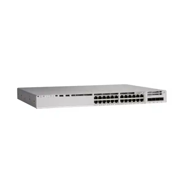
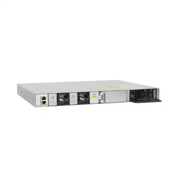
Cisco Catalyst C9200-24P Network Switch
A resilient 24-port Gigabit PoE+ access switch for organizations that need enterprise-class wired connectivity, modular uplinks, stackable operations and a controlled migration path to modern Cisco campus management.
The C9200-24P belongs to Cisco’s modular-uplink Catalyst 9200 family. It combines 24 10/100/1000BASE-T PoE+ access ports with a replaceable uplink network module, StackWise-160 stacking, dual power-supply slots and field-replaceable fans. This architecture is particularly useful when a UAE branch, school, hospitality property, commercial building, clinic, warehouse or distributed enterprise wants a standardized access-layer platform without moving immediately to a higher-cost multigigabit switch on every closet.
What the Cisco C9200-24P is designed to do
The C9200-24P is primarily an enterprise access-layer switch. In practical terms, it is intended to aggregate user-facing Ethernet devices at the wiring-closet or branch level and connect that access layer upstream to distribution, core, firewall or routed infrastructure. Its 24 copper downlinks operate at 10/100/1000 Mbps, and the model provides PoE+ across the access ports so that compatible endpoints can receive both data and electrical power over the same structured cabling. Typical powered devices include IP phones, Wi-Fi access points, fixed cameras, badge readers, room-booking panels, access-control equipment and other standards-compliant edge devices.
The value of the modular C9200 platform is not just the port count. Unlike fixed-uplink C9200L variants, the C9200-24P accepts supported network modules for uplink connectivity, which gives a network designer more flexibility when deciding between Gigabit and 10 Gigabit fiber aggregation. It also supports Cisco StackWise-160, allowing multiple compatible C9200 units with the same license level to operate as one logical stack. For growing sites, that means a business can begin with a single access switch and later add stack members without redesigning the entire access-layer management model.
For organizations sourcing Cisco infrastructure in Dubai and across the Emirates, FourTeck can position the C9200-24P as part of a complete access-network bill of materials rather than as an isolated chassis. That broader approach should include the correct license tier, subscription term, uplink module, optics, secondary power supply where required, stack kits and cables, rack power planning, patching, VLAN and routing design, and post-installation configuration. Related UAE networking and infrastructure capabilities are available through FourTeck UAE.
24 full PoE+ downlinks
All 24 access ports are 10/100/1000BASE-T interfaces capable of IEEE 802.3at PoE+ operation. PoE+ supports up to 30 W at the switch port for a standards-compliant powered device, subject to the total power budget available from the installed power-supply configuration. The switch dynamically allocates PoE power, so the design should be based on actual endpoint draw, class, startup behavior and growth margin rather than assuming that every connected endpoint consumes its maximum nameplate wattage continuously.
Modular uplink architecture
The C9200-24P uses modular uplink options rather than permanently fixed uplink ports. Supported configurations include four-port 1 Gigabit and four-port 10 Gigabit network modules. This makes the chassis attractive where a site standard may change over time: a branch can be commissioned on existing 1G fiber infrastructure and later migrate to 10G aggregation by changing the uplink module and optics, subject to the chosen network design and compatibility requirements.
Hardware architecture and verified platform capacities
The C9200-24P is built as a 1RU modular enterprise access switch with front-panel copper downlinks and rear field-replaceable components. Cisco specifies a switching capacity of 128 Gbps and a forwarding rate of 95.23 million packets per second for the standalone switch. When the platform is deployed with stacking, Cisco lists 288 Gbps switch capacity with stacking and a 214 Mpps forwarding rate with stacking. These values are platform capacities and should not be treated as a promise that every real-world traffic mix will reach a theoretical maximum under all software features, ACLs, telemetry policies and oversubscription conditions.
Scale figures matter during design because an access switch is often asked to do more than simply forward frames. User segmentation, voice VLANs, routed access, multicast, access-control lists, telemetry and network-management functions all consume finite resources. A technically sound deployment therefore checks the expected number of endpoints, VLANs, routed interfaces, prefixes, ACL entries and observed flows against the intended software release and license tier before standardizing the platform across a large estate.
PoE+ engineering: 370 W standard budget and 740 W with a second 600 W PSU
Cisco lists the PWR-C6-600WAC as the default primary power supply for the C9200-24P. With a single 600 W AC supply, the available PoE power is 370 W. Adding a second supported PWR-C6-600WAC raises available PoE power to 740 W. This distinction is crucial because the switch has 24 ports capable of PoE+, but the phrase “24 full PoE+ ports” describes interface capability rather than guaranteeing 30 W simultaneously on all 24 ports with only one power supply installed.
A simple planning example shows why. Twenty-four devices drawing 15 W each require 360 W, which fits within a 370 W PoE budget with very little remaining margin. Twenty-four devices drawing the full 30 W PoE+ maximum would require 720 W, which exceeds the single-supply budget but fits within the 740 W available budget when the second matching AC supply is installed. Real deployments rarely have every endpoint at identical maximum consumption, so a more useful calculation is to list each powered-device type, its expected draw, worst-case draw, startup requirement, count and future expansion factor.
Use the 370 W budget when the endpoint mix is dominated by IP phones, low-power cameras and moderate-power access points, or where the deployment intentionally limits PoE demand. Leave headroom for device replacement and for models whose startup or peak draw exceeds their normal average.
Use two supported 600 W AC supplies when the closet must support a dense PoE+ load, when redundancy is required, or when the organization wants enough aggregate PoE capacity for high-power wireless, video or IoT growth. Redundancy and power-budget objectives should be evaluated together because a failure scenario changes the available power.
For critical sites, do not size only for normal operation. Ask what should happen if one power supply, UPS feed or branch circuit fails. A switch can remain operational while the surviving power budget becomes insufficient for all powered endpoints, depending on configuration and load. PoE priority should therefore be aligned to business importance: voice handsets, critical wireless APs, security devices and access-control endpoints may need a higher restoration priority than noncritical IoT devices. This is an operational design decision, not merely a purchasing decision.
IEEE 802.3at PoE+ also simplifies structured cabling. A properly designed Category cabling plant can carry both power and data to edge devices, reducing the need for local electrical outlets at every AP, phone or camera location. That can be valuable in UAE commercial towers, warehouses, schools and hospitality environments where ceiling or corridor power changes are disruptive. Cabling category, bundle size, conductor quality, ambient temperature and local installation practice still need to be engineered correctly because higher PoE loads can increase cable heating.
Uplink module strategy: when to choose 1G and when to choose 10G
The modular uplink is one of the most important reasons to select the C9200-24P instead of a fixed-uplink access model. Cisco supports four-port 1 Gigabit and four-port 10 Gigabit uplink network-module options for this switch class. The correct choice is not simply “10G is better.” It should reflect the traffic profile, upstream switch capability, fiber plant, redundancy design, optics standardization and expected life of the access closet.
A four-port 1G uplink module can be adequate for a lightly loaded branch with moderate internet-bound traffic, limited east-west application demand and a small number of Wi-Fi access points. It can also be useful when the building’s installed fiber plant, aggregation switch or legacy architecture is standardized on Gigabit optics. The tradeoff is less headroom for future wireless density, local servers, high-resolution video, backup traffic and increased application concurrency.
A four-port 10G uplink module is generally more appropriate when the switch aggregates modern access points, cameras, engineering workstations, local virtualization hosts or a high number of concurrent users, or when multiple access switches feed a 10G-capable distribution layer. With 24 Gigabit downlinks, the access layer can theoretically source far more than 1 Gbps in aggregate, so using 10G upstream connectivity reduces a common bottleneck. Designers can also use multiple uplinks with EtherChannel or cross-stack EtherChannel in a stack, subject to topology and upstream platform design.
Fiber optics must match distance and medium. Multimode short-reach links, single-mode long-reach links and other supported SFP/SFP+ choices have different optical budgets and cabling requirements. Avoid treating “SFP+” as a universal transceiver specification. The switch, network module, optic, fiber type, connector plant and upstream interface must be compatible as one system.
128 Gbps switching capacity
This platform capacity gives the switch internal bandwidth suitable for enterprise access-layer forwarding. Capacity must still be interpreted alongside the physical port mix and real uplink bandwidth. A switch can have a high internal switching capacity while a site remains constrained by a 1G uplink, an oversubscribed firewall path or an upstream WAN service. Performance engineering therefore follows the complete path, not one datasheet number.
95.23 Mpps forwarding rate
Packet forwarding rate matters when workloads generate large numbers of small packets, as happens with voice, transactional applications, telemetry, security events and dense endpoint populations. For routine office access, many deployments will be limited by traffic demand long before reaching platform forwarding scale, but the published rate is useful when comparing models and checking the performance envelope for standardized campus designs.
StackWise-160: scaling beyond one switch without creating eight separate islands
The modular Catalyst 9200 models support StackWise-160 with 160 Gbps stacking bandwidth. Cisco documents support for up to eight members in a compatible C9200 stack, using the C9200 Stack Kit and supported stacking cables. StackWise is not the same as simply connecting switches together with Ethernet uplinks. A properly built stack operates as a coordinated logical system, simplifying management and creating design options such as cross-stack EtherChannel to upstream infrastructure.
Stacking is especially valuable in access closets where port demand is expected to grow from 24 to 48, 72 or more endpoints. Instead of assigning independent management workflows and uplinks to each switch, a stack can present a consolidated operational model. This can reduce configuration drift, make switch replacement procedures more predictable and allow physical links to be distributed across different stack members for improved resiliency. It also creates a cleaner path for adding port capacity without redesigning VLAN gateways, monitoring and authentication policy every time another access switch is installed.
Compatibility rules matter. Cisco states that modular C9200 switches can stack with other C9200 models of the same license level, while mixed stacking between modular C9200 and fixed C9200L models is not supported. A procurement team should therefore avoid combining C9200 and C9200L hardware in a single planned stack unless the design specifically separates them. The stack kit is optional hardware; it should be included in the quotation when stacking is required rather than assumed to be automatically present in the chassis box.
Cable length is another physical planning detail. Cisco offers stack cable options including 0.5 m, 1 m and 3 m lengths. The correct length depends on rack position, cable-management path and whether stack members are adjacent or distributed within the same cabinet. Longer than necessary stack cables can create poor rack hygiene; cables that are too short can force undesirable switch positioning. A rack elevation should therefore be finalized before the stack BOM is closed.
High availability with field-replaceable power and cooling
The C9200-24P provides two power-supply slots and field-replaceable fans. This is an important operational distinction from lower-end fixed access switches because failures can be handled by replacing a component rather than immediately replacing the entire chassis. A second supported power supply can provide redundancy as well as additional PoE capacity, depending on the installed configuration and load. The platform is therefore suitable for access closets where service continuity matters but a full chassis-level dual-supervisor architecture would be unnecessary or too expensive.
High availability is also a topology question. Redundant power does not protect against an uplink failure, cable cut, upstream distribution failure or configuration error. A resilient design can combine dual power feeds, UPS-backed circuits, redundant uplinks, port channels, stack diversity and appropriate spanning-tree or routed-access behavior. Cross-stack EtherChannel can place uplink members on different physical stack units so that an individual member failure does not necessarily remove the entire logical uplink bundle.
For branch locations where only one upstream firewall or router exists, it may be more cost effective to preserve switching availability and accept a single upstream failure domain. For larger campuses, healthcare sites, schools and logistics facilities, the business impact of an access outage may justify dual upstream distribution devices and carefully designed Layer 2 or Layer 3 redundancy. FourTeck’s UAE IT services team can integrate switching, cabling, wireless, firewall and server-room requirements into one implementation scope when a site needs coordinated deployment rather than hardware supply alone.
Security architecture at the wired edge
Modern access switching is part of the security boundary. The Catalyst 9200 platform supports capabilities such as 802.1X access control, policy-based segmentation, access-control lists and 128-bit AES MACsec on C9200 models, with exact feature availability dependent on software release and licensing. These controls can help a business determine who or what is allowed onto a wired port, place endpoints into the right logical segment, restrict traffic paths and protect selected Ethernet links against interception or tampering.
IEEE 802.1X is particularly important for enterprises moving away from the assumption that anything connected to a wall jack is trusted. When combined with an authentication and policy infrastructure, the switch can participate in user and device admission workflows. Printers, IP phones, cameras and building systems may require different methods than managed laptops, so a realistic rollout normally combines 802.1X with device profiling, MAC-based exceptions where unavoidable and tightly controlled fallback policy. The operational objective is to reduce uncontrolled access without breaking legitimate endpoints.
MACsec provides link-layer encryption based on IEEE 802.1AE. Cisco lists AES-128 MACsec support for the C9200 family. This can be valuable for selected switch-to-switch links or other supported designs where sensitive traffic traverses cabling that is not fully trusted. MACsec is not a replacement for end-to-end application encryption, IPsec or firewall policy; it protects Ethernet links at a different layer. It should therefore be used as part of a layered security design.
Network segmentation remains fundamental. Users, voice, wireless infrastructure, cameras, printers, building-management devices and guest systems should not automatically share unrestricted Layer 2 reachability. VLANs, SVIs, ACLs, identity policy and upstream firewall controls can work together to limit lateral movement. For Internet-edge or inter-VLAN security projects, organizations can coordinate the access layer with specialized firewall design through Firewall Dubai by FourTeck.
Layer 2 capabilities for campus access
A stable Layer 2 design is usually intentionally boring. The goal is not to enable every protocol but to create predictable failure domains, consistent trunking, controlled native VLAN behavior, safe edge-port templates, storm control where appropriate and documented topology. PortFast and BPDU protection policies, unused-port shutdown, DHCP-related protections and endpoint authentication should be standardized through templates so the switch estate behaves consistently across branches and closets.
Layer 3 switching and routed-access considerations
Cisco positions the Catalyst 9200 family with Layer 3 capabilities including routed access and routing protocols such as OSPF, EIGRP, IS-IS and RIP, with exact protocol and scale availability dependent on the software release and Network Essentials or Network Advantage entitlement. The C9200 platform lists up to 14,000 IPv4 routes in its scale table, including direct and indirect routes, along with 4,000 IPv4 routing entries and 2,000 IPv6 routing entries. These values show that the platform is more capable than a simple Layer 2 edge switch, but licensing and design intent should be validated before using it as a routing-heavy aggregation device.
Routed access can reduce the size of Layer 2 failure domains by moving the Layer 3 boundary closer to users. Instead of extending user VLANs across many closets, each access block can have routed uplinks to distribution. This can simplify spanning-tree behavior and improve convergence characteristics, but it also changes DHCP relay, gateway redundancy, policy enforcement and monitoring. A campus should choose routed access because the architecture benefits from it, not simply because the switch can run a routing protocol.
Smaller branches often remain best served by Layer 2 access with an upstream firewall or router acting as the default gateway for user VLANs. That keeps policy centralized and can simplify troubleshooting. Larger campuses may benefit from SVIs and dynamic routing at the access layer. The correct design depends on failure-domain requirements, application traffic, operational skill, segmentation policy and the capabilities of the distribution and security layers.
IPv6 planning should also be deliberate. Enabling dual stack without appropriate RA Guard, DHCPv6 controls, ACLs, monitoring and address-management processes can create blind spots. Conversely, ignoring IPv6 while endpoints and applications increasingly support it can leave unmanaged traffic paths. The C9200 should therefore be integrated into the organization’s IPv6 security and addressing strategy rather than treated as an isolated Layer 2 appliance.
QoS for voice, wireless and business applications
Access switches often carry a mixture of delay-sensitive voice, interactive collaboration, ordinary web traffic, backups, camera streams and bulk software distribution. Quality of Service does not create bandwidth, but it can classify, mark, police and queue traffic so that scarce bandwidth is used according to business priority. The C9200 platform provides enterprise QoS capabilities and scale, with Cisco listing up to 1,000 QoS scale entries for the C9200 class.
The most important QoS design question is where to trust markings. Blindly trusting DSCP values from every desktop allows applications or users to claim high-priority treatment. A common design trusts known managed devices such as IP phones or applies classification at the access edge based on application, VLAN or policy. Markings should remain consistent across the switch, wireless network, WAN, firewall and service-provider boundaries where end-to-end treatment is required.
Voice deployments benefit from predictable access-port templates: data and voice VLAN separation, PoE priority, LLDP/CDP behavior where appropriate, 802.1X/MAB policy, QoS trust and spanning-tree edge configuration. Wireless AP ports may be trunks or access ports depending on the WLAN architecture, and their traffic can burst substantially as clients move or software updates are distributed. Camera networks generate sustained streams rather than short interactive bursts, so they must be included in uplink and storage-path capacity planning.
QoS should be validated under congestion. A policy that looks correct when links are idle may not behave as expected during backups, large file transfers or WAN saturation. Test plans should include real application traffic, packet captures, queue statistics and failure scenarios so the operational team understands what is prioritized and what is intentionally deprioritized.
Visibility with Flexible NetFlow and telemetry
Cisco lists support for Flexible NetFlow on the Catalyst 9200 platform, with up to 16,000 flow entries on the 24- and 48-port Gigabit Ethernet models. Flow telemetry can help network teams understand who is communicating with whom, which applications consume bandwidth, how traffic patterns change over time and where unexpected behavior appears. It is particularly useful when users report “the network is slow” but interface counters alone do not reveal the application or host responsible.
Flow data is not the same as full packet capture. It summarizes conversations and traffic attributes, which makes it suitable for longer-term visibility at a much lower storage cost than recording every packet. A monitoring platform can use these records to identify top talkers, unusual destination changes, traffic spikes or unexpected east-west communication. Sampling, record definition, export frequency and collector capacity should be tuned so monitoring does not become unnecessarily heavy.
SNMP, syslog, streaming telemetry and controller-based management can complement flow data. A mature operations model monitors interface errors, PoE draw, temperature, fan and power-supply status, uplink utilization, spanning-tree changes, authentication failures, stack health and software compliance. Alerts should be actionable. Hundreds of low-value notifications create alarm fatigue and can obscure the few events that actually threaten service continuity.
Before rollout, define who receives network alerts, which events trigger tickets, how long logs are retained, which NTP source keeps devices time-synchronized and how configuration backups are protected. These operational foundations often deliver more practical value than enabling a large number of advanced features without a support process.
Cisco IOS XE operations, automation and lifecycle management
The C9200-24P runs Cisco IOS XE, giving network teams a familiar enterprise software environment for configuration, monitoring and automation. Traditional CLI workflows remain available, while larger environments can integrate controller-based management and API-driven processes. The correct operational model depends on the size of the estate. A business with three switches may reasonably use standardized CLI templates and scheduled backups; an enterprise with hundreds of access switches benefits far more from centralized inventory, software compliance, configuration assurance and automated policy deployment.
Software lifecycle discipline is essential. IOS XE releases introduce new capabilities, security fixes and platform changes, but production networks should not upgrade merely because a newer image exists. Establish a validated release policy, review field notices and security advisories, test representative hardware in a lab or pilot site, confirm boot variables and storage, verify feature compatibility, preserve configuration backups and define a rollback procedure. Stacks require additional attention because all members need compatible software and upgrade behavior.
Automation should reduce variance. Device naming, management VLANs, AAA, NTP, DNS, SNMP, syslog, interface descriptions, VLANs, spanning-tree protections, access-control policy and monitoring destinations are all suitable for templates. The aim is not automation for its own sake; it is predictable configuration at scale, auditable changes and faster recovery when a switch must be replaced.
Configuration ownership should also be defined. If both a controller and engineers change the same settings independently, configuration drift and overwritten changes can occur. Decide which system is authoritative for each policy domain, document emergency-change procedures and regularly compare intended state against running state.
Licensing: Network Essentials, Network Advantage and current subscription ordering
Cisco offers the C9200-24P in Network Essentials and Network Advantage variants, commonly represented by hardware orderable SKUs such as C9200-24P-E and C9200-24P-A. The base Network Stack license is perpetual and tied to the selected tier, while Cisco’s current ordering model for new Catalyst 9200 purchases also requires an aligned Cisco Catalyst or Cisco DNA software subscription in Essentials or Advantage. Subscription terms are typically offered for three, five or seven years. Because Cisco licensing programs evolve, the quotation should be checked against the current Cisco ordering guide at the time of purchase rather than copied from an old bill of materials.
Network Essentials provides foundational switching, routing, automation, visibility and security capabilities. Network Advantage adds more advanced routing, segmentation, multicast, scale and security features. Cisco’s add-on software tiers likewise differentiate Essentials and Advantage functionality for automation, assurance, analytics and policy capabilities. The key procurement rule is alignment: the network license tier and selected subscription must be ordered in a supported combination.
Do not decide the tier solely on a feature list copied from a generic Catalyst comparison. First identify the required protocols and functions: dynamic routing, advanced segmentation, controller features, assurance, telemetry depth, policy requirements and future roadmap. Then validate those needs against the exact IOS XE release and licensing matrix. This avoids two common problems: paying for Advantage when the site will never use the additional capabilities, or standardizing on Essentials and later discovering that a planned routing or segmentation feature requires an upgrade.
Smart Licensing and software-subscription management also require operational ownership. The customer should know which Smart Account or Cisco licensing organization will own the entitlement, who can administer it, and how renewal dates are tracked. For managed estates, licensing records should be part of the asset-management database so hardware replacement, RMA events and software renewals do not become emergency tasks.
Deployment patterns for the C9200-24P
Branch office access
A single C9200-24P can serve a branch with users, VoIP phones, APs, printers and a small number of security or building devices. One or two fiber uplinks connect the switch to a branch firewall, router or local aggregation device. The design can remain Layer 2 with gateways on the firewall, simplifying local operations while still providing enterprise switching features.
Campus wiring closet
Two or more C9200 units can be stacked for higher port density. Dual 10G uplinks can be distributed across stack members and connected to redundant distribution switches. User, voice, AP and IoT VLANs can be segmented consistently, while centralized authentication and monitoring enforce enterprise policy across the closet.
IP telephony access
PoE+ allows the switch to power compatible phones, and access-port templates can combine voice VLAN, data VLAN, QoS and authentication behavior. Power calculations should include handset models, expansion modules and any pass-through devices. Dual PSUs may be justified where voice service is considered business critical.
Camera and IoT aggregation
Cameras, badge readers and sensors can use PoE+ while being isolated into dedicated VLANs. Because camera traffic can be sustained and storage-bound, uplink sizing must include aggregate video bitrate, recording server location and failover behavior. IoT segmentation should restrict unnecessary lateral and internet access.
Wireless access-layer use
The C9200-24P can power standards-compliant PoE+ wireless access points, making it useful for Wi-Fi 5 and many Wi-Fi 6 access deployments where each AP uses a 1 Gigabit Ethernet connection and does not require multigigabit switching. The most important limitation is physical interface speed: the C9200-24P provides 1G copper access ports, not mGig downlinks. If the chosen AP has 2.5G, 5G or higher Ethernet capability and the design expects to use that throughput, a multigigabit access model should be considered instead.
This is a common sizing mistake. An AP may function perfectly on a 1G PoE+ port, yet its wired interface becomes the maximum Ethernet throughput path. In many branch and office networks that is completely acceptable because real user traffic does not sustain more than 1 Gbps per AP. In high-density auditoriums, universities, large meeting areas or sites with heavy local traffic, the wired bottleneck can become material. The switch should therefore be selected after the WLAN capacity model is complete, not before.
PoE draw must also match the AP’s operating mode. Some access points reduce radio capability when insufficient power is available. Validate the AP’s required PoE standard, maximum draw and fallback behavior. A 370 W single-supply budget can support many typical AP deployments, but a dense 24-AP design should be calculated carefully and may justify the second power supply.
Wireless uplinks concentrate traffic. If multiple APs terminate on one C9200-24P, a 10G uplink module is usually the more future-ready choice, even when each individual AP uses a 1G access port. This allows aggregate client traffic, tunnel traffic and controller-bound traffic to leave the access switch without being artificially restricted by a single 1G upstream link.
Physical installation, rack depth and environmental planning
Cisco lists the C9200-24P chassis dimensions at approximately 4.4 × 44.5 × 35.0 cm (H × W × D), with a chassis-plus-field-replaceable-power-and-fan depth of approximately 39.1 cm. The listed weight is about 5.5 kg. Although these dimensions fit standard rack environments, the rack design must also allow space for power cords, stack cables, uplink fibers, airflow and cable-management hardware. A cabinet that technically accepts a 1RU chassis can still be operationally poor if rear clearance is insufficient.
Airflow and cooling matter in UAE equipment rooms where ambient conditions can be demanding. Network closets should be cooled and kept within the switch’s documented environmental limits. Do not depend on corridor air leakage or an office split AC whose operating schedule turns off after business hours. PoE switches generate additional heat because electrical power for endpoints passes through the chassis. UPS capacity and cooling calculations should therefore reflect both switch consumption and PoE load.
Rack power should be mapped before installation. If dual power supplies are being used for resilience, place them on independent PDUs or UPS-backed circuits where the site infrastructure supports it. Plugging both supplies into the same single PDU may provide power-supply redundancy but does not protect against PDU, outlet or upstream circuit failure. Label each feed, record breaker information and keep power-cord routes separate from high-density patch leads where possible.
For server-room and rack-infrastructure projects, network switching can be coordinated with compute, UPS and cabinet planning through FourTeck Server Dubai. The practical benefit is a single physical design that accounts for rack units, patching, fiber management, power feeds and cooling rather than treating each device category independently.
UAE-specific deployment and procurement considerations
A technically correct switch can still become a poor procurement decision if regional logistics are ignored. UAE projects often involve tight handover schedules, fit-out coordination, multi-site rollout windows and a mix of locally stocked and distributor-sourced Cisco components. The complete requirement should therefore be frozen early enough to secure the correct switch variant, subscription term, uplink module, optics, stacking hardware and secondary power supplies. Missing a small accessory can delay commissioning as effectively as missing the switch itself.
Power cords and electrical standards must match the destination rack and PDU. Fiber optics should be selected to match the actual installed fiber type and measured distance, not just the building specification. Existing multimode plants can contain mixed OM generations, undocumented patch panels or old connectors. Where there is uncertainty, inspect and test the fiber before ordering a large quantity of transceivers. For single-mode campus links, confirm pathway, attenuation and patching rather than assuming every dark fiber pair is serviceable.
Language and labeling are operational considerations as well. Enterprise networks benefit from a consistent naming convention for sites, closets, racks, switches, uplinks and ports. In multi-tenant or facilities-heavy environments, network labels should be clear enough that IT teams, contractors and building engineers can identify equipment without guessing. As-built documentation should include rack elevations, logical diagrams, IP addressing, VLAN allocation, uplink fiber identifiers, stack-member serials and power-feed information.
Warranty and support coverage should reflect outage cost. Cisco’s hardware warranty provides baseline protection, while customers with stricter response objectives may require appropriate Cisco support services and local implementation assistance. The right service level is different for a spare-equipped small office than for a 24×7 warehouse, clinic or customer-facing property where access-network failure immediately affects operations.
How to size a C9200-24P deployment correctly
Start with endpoint count, but do not stop there. Count current active ports, known near-term additions, conference-room devices, APs, phones, cameras, printers, building systems and spare desk locations. Then reserve growth. A 24-port switch with 23 planned connections on day one leaves almost no operational flexibility. In many branches, it is better to standardize on a second switch or a larger model than to fill every port and force an emergency expansion during the first office move.
Next calculate PoE. Build a device table with quantity, normal draw and maximum draw. Sum the expected and worst-case values, then compare them with the 370 W single-PSU budget and the 740 W dual-600W-PSU budget. Include a margin for endpoint replacements. A future AP model may draw more power than the current one even if the port count is unchanged. If the deployment requires operation after a power-supply failure, evaluate the surviving budget and configure power priority accordingly.
Then size uplinks. Estimate busy-hour user traffic, wireless aggregate demand, camera streams, local-server flows, backup jobs and WAN bandwidth. Consider whether both upstream links will forward simultaneously or one serves mainly as redundancy. For a new design expected to remain in service for several years, 10G uplinks are frequently the practical choice because they provide more headroom and align with common modern distribution platforms. Existing 1G fiber environments can still justify a 1G module when traffic demand is modest.
Decide whether stacking is required. Stacking is useful when multiple switches share one closet and should be managed as a logical unit, when cross-stack uplink resiliency is desired or when port growth is likely. If stacking is not required, independent switches can reduce shared control-plane dependencies and may be simpler in very small branches. Both models can be valid; the choice should follow operations and failure-domain objectives.
Finally validate software features and license tier. Write down every function the network intends to use and map it to the current Cisco licensing matrix and target IOS XE release. Do this before purchase. Licensing is much easier to solve on a quotation than during a midnight change window after discovering that a required feature is unavailable under the chosen tier.
C9200-24P compared with common alternatives
Recommended bill-of-materials checklist
A production quotation should specify more than “one Cisco C9200-24P.” At minimum, confirm the exact license variant and software subscription term, the uplink network module, required SFP or SFP+ transceivers, patch cables, stack kit and stack-cable length if stacking is planned, primary and optional secondary power supplies, country-appropriate power cords, rack mounting hardware, support coverage and any spares strategy. If a site is being migrated from older Catalyst hardware, add temporary optics or patching needed to support the transition topology.
For PoE-heavy environments, document the powered-device inventory and the required failure behavior. If the design depends on 740 W of available PoE, the second 600 W supply is a functional requirement rather than an optional resilience upgrade. If the design needs dual power feeds, ensure the rack actually has independent suitable feeds. A quotation that includes two PSUs but one unsplit PDU does not create end-to-end power redundancy.
For stacks, include StackWise kits for the members that require them and the correct cable lengths. Verify that the planned switch models and license levels are stack-compatible. Reserve rack positions so stack cables can be routed cleanly. Record stack-member priority and replacement procedures in the operations runbook, and keep a documented method for adding or replacing a member without unexpectedly changing switch numbering or interface references.
For optics, standardize on a small number of validated transceiver types wherever practical. Mixed optics from different vendors, undocumented fiber and inconsistent DOM behavior can increase troubleshooting time. The cheapest transceiver on a quote is not necessarily the lowest-cost decision over the full network lifecycle.
Migration from older access switches
Many C9200-24P projects replace older Catalyst 2960, 3560, 3750 or earlier access platforms. A migration should begin with a configuration and dependency inventory rather than a direct copy-and-paste exercise. Old configurations often contain obsolete commands, temporary VLANs, unused trunks, insecure SNMP communities, permissive access lists and years of undocumented exceptions. Recreating every historical line on the new switch can preserve technical debt.
Build a clean target template based on current requirements. Map each old interface to its endpoint, VLAN, voice setting, PoE need and special policy. Verify trunks and allowed VLAN lists. Review spanning-tree root placement, EtherChannel mode, routing adjacencies, DHCP helper addresses, authentication methods and management services. If MACsec, 802.1X or new telemetry is being introduced, deploy those functions in controlled phases rather than changing everything during the physical hardware swap.
Physical migration planning should minimize user disruption. Pre-stage the switch with the correct IOS XE release, license state, hostname, management IP, VLANs and templates. Label patch leads before removing them from the old switch. Where possible, move endpoints in logical groups and validate voice, DHCP, DNS, authentication and application reachability after each group. Keep a tested rollback path until the site is accepted.
After cutover, remove the old switch from monitoring and asset systems only after the new device is fully documented. Capture serial number, rack position, software release, license tier, uplink optics, stack role, power feeds and support contract details. Good records reduce the time required for every future incident, upgrade and audit.
Operational hardening checklist
Security hardening should be staged and monitored. Features such as DHCP snooping or 802.1X can cause service outages if trust boundaries, relay behavior or endpoint exceptions are wrong. Pilot changes on representative users, collect logs, document rollback commands and expand only after the support team understands failure symptoms and remediation procedures.
Why C9200-24P fits many UAE mid-market and enterprise sites
The C9200-24P occupies a useful middle ground. It is more serviceable and flexible than a basic fixed-uplink access switch, yet it remains focused on mainstream Gigabit edge connectivity rather than premium multigigabit performance. The 24-port form factor works well for branches and smaller closets, while StackWise-160 provides a path to higher density. Modular uplinks allow organizations to choose the upstream speed appropriate to the building rather than locking the chassis permanently to one uplink type.
Its PoE design also matches common office and facilities requirements. A 370 W budget with the standard 600 W supply is enough for many mixed phone, AP and camera environments. The optional second 600 W supply can increase available PoE power to 740 W and add power-supply resilience. This makes it possible to design around both endpoint density and business continuity without moving to an entirely different access-switch family.
The platform’s Cisco IOS XE software, 4 GB DRAM, 4 GB flash, 32,000 MAC scale, 512 SVIs, jumbo-frame support, Flexible NetFlow scale and enterprise routing capabilities give it a broad operational envelope for branch and campus access. Not every deployment needs these limits, but the headroom helps organizations standardize on a common platform across varied sites.
The deciding factors should still be objective. If the site needs multigigabit access, evaluate a different model. If 48 ports are required immediately and rack space is constrained, compare a 48-port platform. If the branch is tiny and has no PoE requirement, a simpler switch may be more economical. The C9200-24P is strongest when its combination of PoE+, modular 1G/10G uplinks, stacking and serviceable hardware aligns with a real operational requirement.
Technical specifications summary
Specifications and software capabilities can change with Cisco revisions, software releases and orderable configurations. Final quotations should be checked against the current Cisco datasheet, ordering guide, licensing matrix and transceiver compatibility information for the exact hardware and software bundle being supplied.
Pre-deployment validation plan
Before a switch reaches the production rack, validate identity, software, licensing, hardware inventory and management connectivity. Record the serial number and product ID, verify the installed power supplies and fans, confirm the uplink module, inspect optics and stack accessories, and check that the intended IOS XE release is loaded. If the switch is part of a stack, pre-stage stack membership and software compatibility in a controlled environment where possible.
Next load the approved baseline configuration. This usually includes hostname, management addressing, DNS, NTP, AAA, SSH, SNMP or telemetry, syslog, banners, VLANs, spanning-tree protections and standardized interface templates. Apply only site-specific differences after the baseline is known to work. Separating global standards from site-specific configuration makes future audits and automation much easier.
Then test access behavior with representative endpoints. Verify a normal workstation, an IP phone with downstream PC if applicable, a wireless AP, a camera or IoT device and any special equipment that uses unusual authentication or PoE behavior. Confirm DHCP, DNS, gateway reachability, application access, voice registration, PoE draw and expected VLAN assignment. Test a deliberately unauthorized endpoint if 802.1X or policy enforcement is in scope.
Finally test resilience. Pull one uplink from an EtherChannel, remove one power feed in a dual-feed design, reload a noncritical stack member and confirm monitoring alerts. These tests expose design assumptions before an actual incident does. Document observed convergence times and operational steps so the support team knows what normal failover looks like.
Decision recap: when the C9200-24P is the right choice
Choose the Cisco Catalyst C9200-24P when the site requires approximately 24 Gigabit copper access ports, meaningful PoE+ capacity, modular 1G or 10G uplinks, StackWise-160 growth, serviceable power and cooling components, and Cisco IOS XE enterprise features. It is particularly well suited to branch offices and access closets where IP phones, wireless APs, cameras and user devices share one managed switching platform.
The most important purchase decision is not the model name by itself; it is the complete architecture. Correctly sized PoE, uplinks, optics, license tier, stack design and support determine whether the switch remains a reliable access platform through its service life.
Quotation input checklist for FourTeck UAE
To produce an accurate C9200-24P quotation, provide the site location, quantity of switches, current and future port count, number and type of PoE devices, preferred Network Essentials or Network Advantage tier if already known, required subscription term, uplink speed, fiber type and approximate distance, need for stack kits, requirement for dual power supplies, preferred support coverage and whether configuration or onsite installation is included. If some items are unknown, provide the network diagram or existing switch model and FourTeck can help translate the requirement into a complete BOM.
FourTeck consultation for Cisco Catalyst C9200-24P in Dubai and UAE
FourTeck can support the C9200-24P as hardware supply, a configured access-switch deployment or part of a broader campus and branch modernization project. A complete engagement can cover design validation, licensing and BOM review, stacking, fiber uplinks, VLANs, Layer 3 routing, PoE planning, authentication, monitoring, migration and handover documentation.
For best results, share the existing network diagram, target rack location, upstream switch or firewall model, endpoint list and growth expectation. That information allows the solution to be sized around the actual traffic and power profile rather than relying on generic assumptions. The result should be an implementation-ready bill of materials with clear responsibilities for optics, patching, licenses, power, support and configuration.
Confirm quantity, license tier, PoE load, uplink speed, fiber type, stacking, second PSU requirement, support level and installation scope. These inputs prevent incomplete quotes and reduce delays during project handover.

Reviews
There are no reviews yet.