
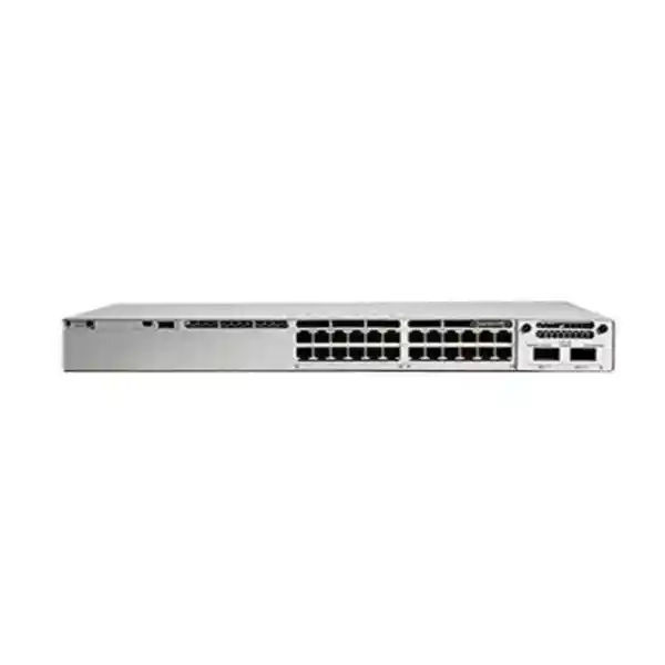
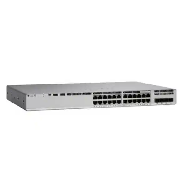
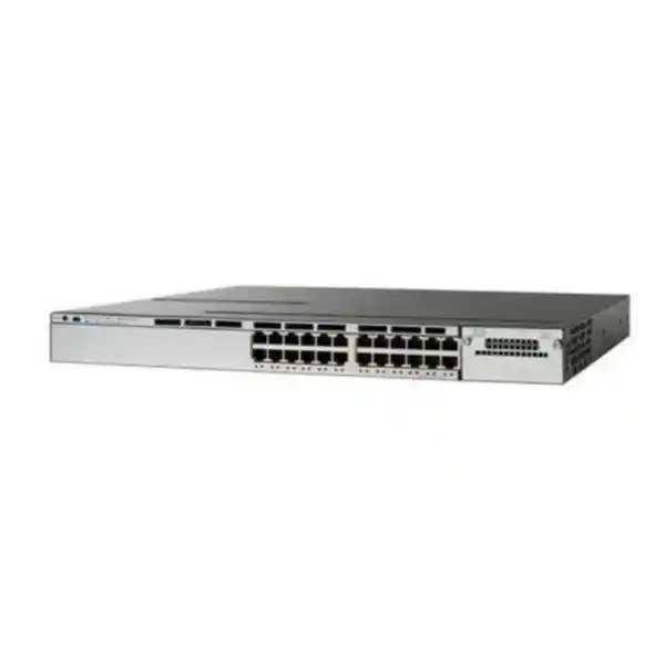
Cisco Catalyst C9200-24PXG Network Switch
The Cisco Catalyst C9200-24PXG is a 24-port, full-PoE+ enterprise access switch designed for organizations that need multigigabit edge bandwidth without stepping into a larger campus switching class. Its front-panel mix of eight multigigabit Ethernet copper ports and sixteen 1 Gigabit Ethernet PoE+ ports makes it particularly suitable for modern Wi-Fi access points, high-performance workstations, collaboration endpoints, IP phones, surveillance devices and other powered edge equipment. Unlike fixed-uplink access switches, this platform accepts modular uplink choices, allowing the same access-layer design to be matched to 10G, 25G or 40G aggregation requirements as the network evolves.
For UAE businesses, the practical value is flexibility: dense PoE+ at the access layer, multigigabit capacity for wireless and bandwidth-intensive users, high-speed stack interconnects, redundant field-replaceable power options and Cisco IOS XE operations in a familiar Catalyst environment. FourTeck can support planning, bill-of-material validation, switch configuration, uplink selection, stacking design, VLAN and routing policy, wireless readiness, migration and onsite deployment through its UAE technology practice.
Eight multigigabit interfaces plus sixteen 10/100/1000 interfaces for mixed-performance edge connectivity.
The eight mGig ports can negotiate 100M, 1G, 2.5G, 5G and 10G Ethernet according to endpoint capability and cabling conditions.
High-speed physical stacking allows multiple switches to be operated as one logical system for resilient access-layer designs.
Supported network modules can provide 10G, 25G or 40G uplink options, enabling better alignment with aggregation capacity and redundancy requirements.
Why the C9200-24PXG Fits Modern UAE Access Networks
Enterprise access switching is no longer only about connecting desktop PCs at one gigabit per second. Wireless access points can aggregate traffic from dozens of users, collaboration rooms can combine video, voice, screen sharing and cloud applications, surveillance systems increasingly use high-resolution streams, and branch offices may depend on cloud applications that create sustained east-west and north-south traffic. The access switch must therefore supply power, bandwidth, policy enforcement and resiliency at the same point in the network. The C9200-24PXG addresses that requirement with a deliberately mixed port architecture. Sixteen conventional 1G PoE+ ports are well suited to IP phones, cameras, printers, thin clients and standard workstations, while eight multigigabit ports are reserved for endpoints that can exceed one gigabit without requiring fiber at the desk or ceiling.
That combination is particularly useful during staged Wi-Fi refresh projects. A company may still operate many 1G wired devices while replacing legacy wireless access points with Wi-Fi 6 or Wi-Fi 6E hardware. Deploying a switch in which every port is 10G-capable can be unnecessary, but using only 1G access ports can create a wired bottleneck behind modern access points. The C9200-24PXG provides a balanced middle path by concentrating multigigabit capability where it is most valuable. It can also protect cabling investments because 2.5G and 5G Ethernet are designed to provide higher throughput over installed twisted-pair cabling where a full 10G copper channel may not be practical.
For branch and campus distribution, modular uplinks are another major planning advantage. The switch can be matched to a 10G aggregation layer in a smaller office, or equipped for 25G or 40G uplink designs where larger wireless, surveillance or user populations justify more capacity. This avoids the common problem of selecting a fixed-uplink access switch whose uplink architecture becomes a constraint before the access ports themselves reach end of life. The result is a platform that can support multiple generations of endpoints while remaining operationally consistent with the Catalyst ecosystem.
Organizations planning a refresh should look beyond raw port count. The correct design considers endpoint classes, PoE draw, uplink oversubscription, stack topology, power-supply redundancy, optical reach, license tier, routing requirements and operational tooling. FourTeck’s UAE IT services team can map these factors into a deployment standard for single-site offices, multi-floor buildings, warehouses, schools, healthcare facilities, hotels and distributed enterprise branches.
Port Architecture: Eight Multigigabit Ports Plus Sixteen 1G PoE+ Ports
The defining characteristic of the C9200-24PXG is its asymmetric access-port mix. The eight multigigabit copper ports support negotiated Ethernet rates from 100 Mbps through 1G, 2.5G, 5G and 10G, while the remaining sixteen copper ports provide conventional 10/100/1000 Ethernet. All twenty-four access ports are PoE+ capable, making the switch suitable for powered network devices without requiring local AC adapters at the endpoint. This architecture allows a designer to classify ports by expected performance rather than treating every endpoint identically.
A typical floor deployment may allocate the mGig ports to wireless access points, high-resolution media workstations, engineering endpoints, network-attached appliances or high-bandwidth meeting-room devices. Standard Gigabit ports can be used for phones, cameras, badge readers, printers, user desks and other equipment whose application profile rarely needs more than 1 Gbps. This approach can improve capital efficiency while still removing the most important access-layer bottlenecks. It also reduces unnecessary change: existing patch panels and horizontal cabling can often remain in service after appropriate certification and testing.
Multigigabit Ethernet should be planned with cabling quality in mind. The fact that a switch port can negotiate 5G or 10G does not guarantee that every installed cable run will reliably sustain that rate. Cable category, connector quality, patch cords, bundle conditions, run length, electromagnetic environment and workmanship can all affect achievable speed. During a network refresh, FourTeck normally recommends mapping the intended mGig endpoints, testing representative runs, verifying switch-to-endpoint negotiation and documenting any links that must be re-terminated or upgraded. This is especially important in older buildings where the cabling plant may predate current wireless capacity requirements.
Port-level configuration should also reflect endpoint function. Wireless access points may need trunking with multiple VLANs, native or management VLAN settings, LLDP, QoS trust policies and power settings. IP phones often use a dedicated voice VLAN alongside a data VLAN for a connected workstation. Cameras typically require access VLANs, PoE monitoring, restricted east-west reachability and rate-aware uplink planning. User ports may need 802.1X, MAC Authentication Bypass for special devices, storm control, DHCP snooping-related protections and edge spanning-tree behavior. A modern access switch is therefore not simply a physical fan-out device; it is a policy enforcement point with direct influence on user experience and security posture.
When the 24-port count is correctly aligned to room density, the C9200-24PXG can create a clean and manageable access block. In larger floors, multiple switches can be stacked and treated as a logical system, allowing port assignments to be spread across stack members while preserving a consistent operational model.
PoE+ Design and Power-Budget Engineering
Power over Ethernet is one of the most important sizing dimensions for this switch. The C9200-24PXG supports full PoE+ access, and Cisco documents a maximum platform PoE budget of up to 740 watts when the switch is equipped appropriately. The actual usable PoE budget in a specific bill of materials depends on the installed power supplies, redundancy mode, system power consumption and the selected power configuration. For that reason, a quotation should never assume that the presence of twenty-four PoE+ ports automatically means every endpoint can draw its maximum PoE+ allocation simultaneously.
A professional PoE calculation starts with the actual device list. Wireless access points should be counted by model and operating mode because radios, USB accessories or high-performance features may increase draw. Cameras should be separated into fixed, PTZ, heated or infrared-equipped categories because their peak consumption can differ significantly. Collaboration devices, door controllers, sensors, IP phones and specialty endpoints should each be assigned a realistic maximum draw. The total should then be multiplied by an engineering headroom factor so that normal additions or transient loads do not consume the entire switch budget.
Redundant power supplies require another design decision. In some environments, the goal is power-supply redundancy: one supply can fail without interrupting switch operation or critical PoE loads. In other deployments, both supplies are used primarily to increase the available PoE budget. These are different objectives and must be reflected in the bill of materials and expected behavior during a failure. Critical sites such as hospitals, hotels, financial offices, command rooms and high-availability warehouses should explicitly document which powered endpoints must remain online after loss of one AC source or one supply.
Power source diversity is equally important. Two switch power supplies connected to the same single PDU and the same upstream circuit do not provide end-to-end electrical resilience. Where infrastructure permits, dual supplies should be fed from independent protected sources or appropriately designed UPS/PDU paths. The network rack should also be assessed for thermal load because PoE switches supplying hundreds of watts to edge devices still consume and dissipate power within the rack environment.
From an operations perspective, PoE visibility can help identify abnormal endpoints, unexpected draw or devices that fail to power after changes. Naming interfaces clearly, recording endpoint type and location, and maintaining a port map improves fault isolation. During handover, FourTeck can provide a PoE allocation sheet that links switch interface, patch-panel position, endpoint, expected draw, VLAN and criticality so future maintenance teams can understand the design rather than reverse-engineer it during an outage.
Modular Uplinks: Building the Right Path to Distribution
The C9200-24PXG uses modular uplink options instead of locking the switch to one fixed uplink configuration. Cisco lists support for network-module choices that can provide four 10G uplinks, two 25G uplinks or two 40G uplinks. This is a significant design feature because the access layer may remain in service for many years while the distribution layer, WAN bandwidth, wireless density and application traffic continue to grow. Selecting the correct uplink module at deployment time allows the switch to fit a specific environment without compromising the chassis choice.
A 10G uplink design can be entirely appropriate for a 24-port branch switch when most users are 1G endpoints and the eight mGig ports are not continuously saturated. Dual 10G links can be used for redundancy and aggregation, subject to topology and design policy. In a dense wireless floor, however, the aggregate traffic generated by multiple mGig access points can justify 25G uplinks. A 40G option may fit designs where the access block feeds a higher-capacity aggregation pair and the goal is to reduce oversubscription or simplify fiber count.
Oversubscription should be calculated from realistic traffic, not simply by adding every port’s theoretical maximum. Twenty-four edge ports rarely transmit at line rate simultaneously, but some environments have bursty workloads that are sensitive to congestion. Wireless networks can generate concentrated peaks during meetings, events, software updates or backup windows. Video surveillance can create sustained streams. Engineering workstations can move large files to local servers. A good design estimates busy-hour traffic, identifies latency-sensitive applications and chooses uplink capacity with both redundancy and growth in mind.
Optics and cabling are part of the uplink design. Fiber type, distance, connector standard, patching, transceiver compatibility and the distribution switch interface must all match the selected module. A 25G or 40G module does not automatically mean every existing fiber path can support the intended service. Existing multimode fiber may be adequate over certain distances with suitable optics, while longer links or future-proofing may favor single-mode fiber. Documentation should record optical type, transmit/receive path, patch-panel positions and spare strand availability.
Where a campus uses redundant distribution switches, uplinks should be designed as part of the broader high-availability architecture rather than as isolated links. Stack topology, port-channel strategy, first-hop redundancy, routing boundary and spanning-tree design all affect how the access switch behaves when a link or upstream device fails. FourTeck can align the C9200-24PXG uplink selection with the organization’s current distribution platform and future refresh roadmap so the access purchase does not create an avoidable bottleneck.
StackWise-160 for Resilient Access-Layer Operations
Cisco positions the modular Catalyst 9200 platforms with StackWise-160, providing a stack interconnect bandwidth of up to 160 Gbps and allowing multiple physical switches to operate as a single logical switching system. The architecture is valuable for access-layer deployments because it can reduce management complexity while improving resilience. Instead of configuring each switch as an isolated island, administrators can manage a stack as one entity, apply consistent settings and use cross-stack connectivity patterns that survive selected component failures.
A stack is most effective when it is intentionally designed. Member placement, stack-cable routing, power feeds, uplink distribution and switch priority should be documented. A ring topology is typically preferred to avoid a single stack-cable break partitioning the interconnect. Physical rack layout should make cable paths serviceable without placing excessive strain on stack connectors. Labels should identify each member and its logical number so engineers can replace hardware without uncertainty.
Uplinks can be distributed across stack members to reduce dependence on one chassis. For example, one uplink in a port channel can originate from one member and another from a different member, depending on the approved network design. This does not eliminate every possible failure mode, but it can reduce the impact of a single member outage. Power supplies should be distributed across protected power sources where possible, and stack members serving critical endpoints can be mapped so that essential services are not unintentionally concentrated on one physical switch.
Stacking also helps capacity growth. A site can begin with one or two switches and add members as port demand increases, within the supported stack design and software requirements. Expansion should still be planned carefully: software versions, license alignment, hardware compatibility, stack numbering, image installation and maintenance windows matter. A newly added member should not be introduced into a production stack without validating the software state and configuration expectations.
Operationally, a well-documented stack reduces routine administration because VLANs, management policy and many interface templates can be handled consistently. It can also simplify troubleshooting by presenting one logical system rather than multiple independently managed access switches. However, stacking is not a substitute for broader architectural resilience. Distribution redundancy, power diversity, structured cabling, monitoring, configuration backup and change control remain necessary. The best outcome is achieved when StackWise-160 is used as one layer in a complete availability design.
Cisco UADP-Based Architecture and Enterprise Packet Handling
Cisco’s architecture documentation identifies the C9200-24PXG as a multigigabit Catalyst 9200 model built with two UADP 2.0 mini ASICs. The significance of this design is that switching, policy and forwarding functions are implemented in purpose-built silicon rather than depending solely on a general-purpose CPU for every packet. For an enterprise access switch, this matters because user traffic, wireless traffic, voice, video and security features may all coexist while the platform continues to deliver predictable forwarding behavior.
The access layer increasingly performs more than Layer 2 forwarding. VLAN segmentation, access control, QoS classification, policing, routing functions, telemetry, multicast handling and security protections can all influence packet processing. Hardware-based forwarding enables the switch to apply supported services efficiently at scale. The specific table capacities, supported feature combinations and software capabilities should always be checked against the intended IOS XE release and license tier, especially for designs with large route counts, extensive ACLs, many policy entries or specialized campus features.
From a practical planning perspective, the switch should be sized for the actual role. A 24-port access switch serving office users and wireless access points has a very different traffic pattern from a switch placed in a camera aggregation closet or an engineering lab. The number of VLANs, MAC addresses, multicast groups, routed interfaces, ACL entries, QoS policies and management features can affect resource usage. Projects with unusual scale or feature density should have the configuration reviewed before procurement rather than assuming all Catalyst 9200 models behave identically under every workload.
ASIC architecture also contributes to consistency across a stack when multiple members are used as one system. Traffic may enter on one member and leave through another, so internal stack capacity and forwarding behavior become part of end-to-end design. This is another reason to avoid viewing the switch as a collection of independent access ports. The chassis, ASICs, uplink module, stack ring and software image operate together as a system.
For buyers comparing the C9200-24PXG with entry-level unmanaged or smart switches, the architectural difference is substantial. The Catalyst platform is designed around enterprise policy, lifecycle management, resiliency and operational visibility. That makes it appropriate for organizations that need repeatable standards, controlled change, auditability and integration with wider Cisco network practices, rather than only basic Ethernet connectivity.
Licensing: Network Essentials, Network Advantage and Software Planning
The C9200-24PXG is offered in Network Essentials and Network Advantage variants, commonly represented by model suffixes such as C9200-24PXG-E and C9200-24PXG-A. The hardware platform is closely related, but the available networking features and software entitlements differ. The correct license selection therefore depends on the intended Layer 2, Layer 3, policy, segmentation and operational requirements rather than on port count alone.
Network Essentials is frequently suitable for straightforward enterprise access deployments that need standard switching, basic routing and common access-layer functions. Network Advantage is selected when the design requires more advanced capabilities. Exact feature availability can change by IOS XE release and subscription packaging, so the project bill of materials should be checked against Cisco’s current software matrix at the time of order. This is especially important for projects that use advanced routing, segmentation, automation or campus architecture capabilities.
Software planning should be treated as a lifecycle subject. A switch may remain in service for many years, during which the organization could adopt new management platforms, security controls or campus design standards. Buying the least expensive license without understanding future requirements can create avoidable upgrade work, while selecting a higher tier without a feature justification can add cost. The decision should be based on a written feature checklist covering routing protocol needs, virtual network requirements, telemetry, automation, policy, management and support expectations.
Cisco IOS XE is the operating system foundation for the Catalyst 9200 family. Production networks should use an approved software release that matches organizational standards, interoperability requirements and security maintenance policy. Before deployment, image version, boot variables, license state, stack compatibility, configuration templates and upgrade path should be validated. Organizations with multiple sites benefit from standardizing on a small set of qualified releases rather than allowing every branch to drift independently.
License and software details are also important during procurement handover. The quotation should identify the exact switch PID, selected network license, any required subscription package, support coverage, uplink module, stack accessories, optics and power supplies. This avoids a common project problem in which the chassis arrives but the final deployment is delayed because an uplink module, power component, cable or entitlement was omitted from the original order.
Secure Access-Layer Design for Users, Phones, Cameras and IoT
A Catalyst access switch should be deployed as a controlled edge, not as a flat extension of the internal network. The C9200-24PXG can participate in an access-security architecture that separates endpoint types, validates devices and limits the impact of common Layer 2 attacks. The exact feature set depends on license and software release, but the design principles remain consistent: identify the endpoint, assign appropriate network access, prevent unauthorized infrastructure behavior and monitor changes.
802.1X is commonly used for authenticated user and device access. Where endpoints cannot support 802.1X, MAC Authentication Bypass may be used under controlled policy, often for printers, cameras, building systems or specialty devices. Voice endpoints can be placed in dedicated voice VLANs, while user data remains in another segment. Wireless access points may carry multiple SSIDs and therefore require trunk interfaces with carefully controlled allowed VLANs. Cameras and IoT devices should generally be placed in restricted segments with firewall policy controlling access to management systems, recording servers or cloud services.
Layer 2 safeguards are equally important. DHCP snooping, Dynamic ARP Inspection, IP Source Guard, BPDU Guard, Root Guard, storm control and port security concepts can reduce the likelihood that a user or misconfigured device disrupts the access network. These controls should be applied through tested templates because incorrect settings can also create outages. For example, enabling a protection feature without correctly defining trusted uplinks or DHCP paths can block legitimate traffic.
Segmentation at the switch should align with upstream firewall policy. A VLAN is not by itself a security boundary if routing between VLANs is unrestricted. Sensitive user groups, guest wireless, cameras, building systems, voice, printers and management interfaces should have documented trust relationships and traffic flows. FourTeck’s Firewall Dubai practice can coordinate access-switch segmentation with next-generation firewall rules so the campus edge and perimeter security design reinforce each other.
Management-plane protection should also be addressed. Switch administration should use secure protocols, dedicated management addressing, role-based access where appropriate, centralized AAA, logging, time synchronization and configuration backups. Unused ports should be disabled or placed in a restricted state, descriptions should identify connected devices, and access to console or management interfaces should be physically controlled. These operational details are often more important to real-world security than a long list of unused features.
QoS for Voice, Video, Wireless and Cloud Applications
Quality of Service is essential when delay-sensitive applications share links with large data transfers. The C9200-24PXG is often deployed at the exact point where diverse traffic classes converge: voice from IP phones, video from conferencing systems, wireless client traffic, surveillance streams, user data, software distribution and cloud application sessions. A practical QoS design identifies trusted marking boundaries, protects real-time applications and prevents bulk traffic from overwhelming constrained uplinks.
Trust should not be applied indiscriminately. An IP phone or managed wireless access point may be permitted to mark traffic according to an enterprise policy, while a general user port may require the switch to classify or remark traffic. Otherwise, any endpoint could mark its own flows as high priority and undermine the policy. The network team should define which devices are trusted, which DSCP or CoS values are permitted and how those values map to queues across the access and distribution layers.
Wireless traffic deserves special attention because many users can share one mGig switch port through a single access point. The switch may see multiple applications and classes on that one interface. If the AP is carrying voice, video and normal data from several SSIDs, the wired QoS design must preserve the intended treatment across the uplink. This is one reason mGig access and sufficient uplink bandwidth work together: increasing access speed without reviewing upstream congestion can simply move the bottleneck.
Surveillance environments create a different challenge. Video streams can be sustained and predictable rather than bursty, so aggregate bandwidth should be calculated from camera resolution, frame rate, codec, recording mode and retention architecture. Large firmware downloads or backup traffic should be prevented from causing latency spikes for voice or interactive applications. Monitoring should be used to confirm whether queues are dropping packets or whether links consistently operate near capacity.
QoS is most successful when it is kept understandable. Overly complex policies are difficult to troubleshoot and are often applied inconsistently between sites. FourTeck can create a small number of reusable templates for user ports, phone-plus-PC ports, wireless access points, cameras, infrastructure links and uplinks. That makes the configuration easier to audit and reduces the risk of site-to-site drift.
Wi-Fi 6 and Wi-Fi 6E Readiness
Cisco specifically positions the C9200-24PXG for Wi-Fi 6 and Wi-Fi 6E wired and wireless converged access. That positioning is rooted in the eight multigigabit access interfaces. Modern wireless access points can offer aggregate radio capacity that exceeds a single 1G Ethernet link, particularly when serving dense user populations or using wider channels. A 2.5G, 5G or 10G wired connection gives the AP more room to move traffic into the LAN without the switch port becoming the first bottleneck.
The right wired speed depends on the actual access point, radio configuration and expected client density. Not every AP needs 10G, and many deployments gain substantial benefit from 2.5G or 5G. The mGig interfaces allow the link to negotiate an appropriate rate rather than forcing a binary choice between 1G and 10G. This is especially helpful in upgrades where existing copper cabling may support intermediate multigigabit rates more reliably than 10G over every run.
Power must be reviewed at the same time as bandwidth. Access points can require more power as radio count and features increase, so the switch’s PoE+ capability and total PoE budget should be checked against the exact AP models. The number of APs per switch, redundant power strategy and expected peak draw should be calculated before purchase. Large wireless projects should also reserve capacity for future AP additions instead of using every available powered port on day one.
Wireless VLAN and security design should be coordinated with the switching configuration. AP switchports may use trunks carrying management, corporate, guest, voice or IoT networks depending on the wireless architecture. Allowed VLAN lists should be restricted to what is required. Native VLAN choices should be standardized. QoS trust and endpoint discovery should match the selected wireless vendor design. Uplink capacity should then be sized from the aggregate demand of all APs on the access switch, not only from the speed of one radio.
For offices in Dubai, Abu Dhabi, Sharjah and other UAE locations, the C9200-24PXG can be an effective migration platform when the business expects wireless demand to grow faster than traditional desk-port demand. Eight high-speed copper interfaces provide room for a meaningful AP population while sixteen 1G ports continue to serve conventional users and building devices.
Deployment Topologies: Branch, Floor, Campus and Specialized Networks
In a small or medium branch, a single C9200-24PXG can serve as the primary access switch when twenty-four powered ports are sufficient. Eight mGig ports can be allocated to access points or high-bandwidth endpoints, while the other sixteen connect ordinary users, phones and building devices. Two uplinks can provide redundant connectivity to a branch firewall, router or distribution pair, depending on the architecture. In this role, the switch provides a compact platform with enterprise operations and growth headroom.
In a multi-floor office, multiple C9200-24PXG switches can be deployed in intermediate distribution frames and stacked where appropriate. Each floor can use a consistent template for management, VLANs, voice, wireless, cameras and users. Fiber uplinks connect the floor stack to a centralized distribution or core layer. This architecture makes troubleshooting easier because interface naming, VLAN numbering and policy can be standardized across the building.
In hospitality, the switch can support wireless access points, IP phones, back-office users, cameras and selected building systems. Hotels need careful PoE and redundancy calculations because many services operate around the clock. Guest and operational networks should be segmented, and access-layer maintenance should be planned so it does not disrupt critical front-desk, payment, telephony or security functions.
Education environments can use the mGig ports for high-density classroom or common-area access points, while standard ports serve teachers, labs, phones, cameras, printers and administrative systems. Schools and universities often experience very concentrated wireless usage at predictable times, making uplink capacity and QoS important. Stack growth can also be useful where new classrooms or devices are added over time.
Healthcare sites require stricter segmentation and availability. Wireless clinical devices, administrative users, phones, cameras and facilities systems may have different risk profiles. Switch configuration should be aligned to organizational security policy, and maintenance must account for 24-hour operations. Redundant power, uplink design, monitoring and configuration backup become especially important.
Warehouses and logistics facilities often use fewer desk ports but more access points, scanners, cameras and industrial-adjacent devices. mGig ports can support high-capacity wireless zones, while PoE+ reduces the need for local electrical outlets. Environmental conditions, rack placement, cable distance and UPS runtime should be reviewed carefully. The Catalyst 9200 is an enterprise indoor switch, so harsh industrial areas may require environmental enclosures or a different switch family.
For organizations extending common standards into Africa, FourTeck can also coordinate broader regional sourcing and design through its Africa network solutions presence, while the UAE deployment can remain aligned to the same switching templates and documentation standards.
Sizing Methodology Before You Order
A reliable C9200-24PXG design begins with a port schedule. List every endpoint by location and type, identify whether it needs PoE, estimate its maximum power draw, and record the bandwidth it can use. Separate the eight mGig candidates from ordinary 1G endpoints. Add spare capacity for growth. If a floor requires more than twenty-four ports, decide whether two 24-port switches or a 48-port model gives the better balance of mGig density, PoE budget, rack space, failure domain and expansion flexibility.
Next, calculate PoE. Add the maximum expected draw of all powered devices and reserve headroom. Determine whether the design must maintain critical PoE after a power-supply failure. Select the number and rating of supplies accordingly. Confirm UPS capacity and expected runtime, especially if the switch powers phones, cameras or wireless access points that must remain available during short power events.
Then calculate uplink requirements. Estimate peak aggregate traffic and decide how much oversubscription is acceptable. Choose between 10G, 25G and 40G uplink options based on the upstream platform, available optics, fiber plant and future growth. For redundant designs, define whether links will operate as port channels, routed links or another supported topology. Check compatibility with the distribution switch before ordering modules and optics.
Stacking should be a deliberate choice. If multiple switches share a rack and management domain, StackWise-160 can simplify operation. Confirm the required stack cables, physical rack layout, member count and software alignment. Leave adequate cable management space and plan how a member can be replaced without disturbing adjacent equipment. Document intended member numbers and uplink locations.
Licensing comes next. Compare Network Essentials and Network Advantage against the actual feature list. Do not base the decision on naming alone. Record required routing, segmentation, security, automation and management capabilities. Confirm any subscription or support requirements with the final Cisco commercial configuration.
Finally, validate the physical environment. The C9200-24PXG is a 1RU-class platform with field-replaceable fans and dual power-supply slots. Check cabinet depth, rail or shelf arrangement, airflow, front and rear clearance, PDU outlet type, available AC circuits, grounding, temperature and cable routing. Cisco documents the chassis at approximately 1.73 x 17.5 x 13.8 inches before additional field-replaceable components are considered in the depth envelope. The rack should be planned around the complete installed system, not only the bare chassis dimensions.
This sizing sequence converts the switch from a generic product into a verified deployment component. It also produces a cleaner quotation because every module, optic, cable, license and power component has a documented reason for inclusion.
Migration Planning from Legacy Catalyst or Third-Party Access Switches
Replacing an access switch is easy only when the existing environment is fully documented. In many real networks, old switches contain years of exceptions: manually configured voice VLANs, static trunks, special camera ports, printers with fixed addressing, disabled interfaces, custom spanning-tree settings, ACLs, old monitoring strings and undocumented uplinks. A successful migration begins by collecting the running configuration and comparing it with the current physical patching.
The migration team should build a port-by-port map showing old interface, patch-panel port, endpoint, VLAN, voice VLAN, PoE requirement, trunk status, speed/duplex behavior, security policy and new target interface. This prevents the common mistake of copying an old configuration blindly to new hardware. Legacy settings that are no longer required should be removed, while valid special cases should be preserved intentionally.
Multigigabit migration adds an opportunity to improve performance. Wireless access points that were previously connected at 1G can be moved to the eight mGig ports. Cabling should be tested and the negotiated rate verified after cutover. If a link falls back to a lower speed, the team can determine whether the endpoint, patch lead, horizontal cable or configuration is responsible.
Uplinks should be migrated with special care because they can affect an entire floor. If the new switch uses a different uplink speed or optic type, both ends must be prepared. Port channels must have matching configuration. VLAN trunks need compatible allowed lists and native VLAN settings. Routed uplinks require correct addressing and protocol configuration. A rollback plan should exist in case the new path does not establish cleanly.
Software and management settings should be standardized before the switch enters production. Set hostname, management addressing, DNS, NTP, AAA, logging, SNMP or telemetry, SSH, banners, interface templates, spanning-tree policy and security controls according to the organization’s baseline. Save a clean configuration backup and record the software release. For stacks, validate member numbering and redundancy before moving user ports.
A phased cutover is often preferable in large sites. One floor or switch group can be migrated, observed and documented before the pattern is repeated. This allows the team to identify hidden dependencies early and refine the template. FourTeck can provide preconfiguration, onsite migration and post-cutover validation so the new Catalyst access layer is delivered as an operational system rather than simply unpacked hardware.
Operations, Monitoring and Troubleshooting
Long-term value depends on how the switch is operated after installation. Every C9200-24PXG should have a defined management address, naming convention, monitoring policy and configuration backup process. Interface descriptions should identify connected endpoints or patch-panel destinations. Trunks and uplinks should be clearly labeled. Stack members should have predictable numbers. These simple practices reduce troubleshooting time more than many advanced tools because engineers can quickly understand what they are looking at.
Monitoring should cover availability, interface utilization, errors, discards, PoE state, temperature, power supply health, fan health, stack status and uplink behavior. High CRC or input error counts can indicate cabling problems. Repeated speed renegotiation on an mGig link may point to physical-layer instability. Output drops can indicate congestion or QoS pressure. Unexpected PoE cycling may reveal an endpoint or power-budget issue. Stack events should be investigated because intermittent stack cabling can create difficult-to-diagnose symptoms.
Baselining is useful after deployment. Record normal CPU, memory, uplink utilization, PoE consumption and error rates during typical busy periods. When users later report poor performance, the support team can compare current values with a known-good baseline. Without this reference, it is easy to confuse normal activity with a fault or overlook a gradual trend toward congestion.
Configuration changes should follow version control or backup discipline. Before major modifications, save the current configuration and document the reason for change. After successful implementation, update the stored baseline. Software upgrades should be tested against critical features and performed during approved maintenance windows, particularly for stacks. Upgrade planning should account for stack behavior, reboot sequence, downtime and rollback options.
Troubleshooting should proceed from physical to logical. Verify link state, cabling, negotiated speed, duplex, errors and PoE first. Then check VLAN membership, trunking, spanning tree, authentication, DHCP and routing. Finally investigate application behavior. This layered method prevents teams from spending time on routing or firewall analysis when the real problem is a damaged patch cord or a port negotiating at an unexpected rate.
For multi-site enterprises, standardized monitoring and templates are especially valuable. A C9200-24PXG in Dubai should present the same operational structure as one in another branch whenever business requirements allow. Consistency reduces support cost, improves security reviews and makes future upgrades easier to automate.
UAE Procurement and Bill-of-Materials Considerations
Enterprise switching procurement in the UAE should start with the exact product identifier rather than only the marketing name. The C9200-24PXG can be ordered with different network license tiers, and the final system may require an uplink module, power supplies, stack accessories, optics, support and software entitlements. A quotation that lists only “C9200-24PXG” without the complete configuration can be misleading because the installed capability depends on those associated components.
The first line item to confirm is the license variant: Network Essentials or Network Advantage. The second is the uplink module. If the design uses 10G, 25G or 40G connectivity, the module and compatible optics should be specified explicitly. Fiber patch cords and connector types should match the site. If the switch will join a stack, the correct StackWise accessories must be included. If redundant power is required, the second power supply and power-cord type must be identified.
Lead time can vary by component. A chassis may be available while a particular uplink module or optic has a different availability window. For project schedules, procurement teams should validate the whole bill of materials rather than assume all components ship together. Large deployments may benefit from ordering a small spare pool of common optics, power supplies or stack cables so a single accessory failure does not create a prolonged outage.
Warranty and support coverage should match business criticality. Organizations with 24×7 operations may require faster replacement or technical support than an ordinary office. The support plan should be reviewed alongside internal spare policy. Some enterprises prefer to keep an onsite spare switch for immediate replacement while using vendor support for replenishment. Others depend on contractual replacement service. The right choice depends on downtime cost, number of sites and local technical capability.
Documentation is part of procurement quality. The final package should identify serial numbers, license information, installed modules, power supplies, stack role, management IP, rack location and support entitlement. This record simplifies future renewals, audits and troubleshooting. It also prevents uncertainty when a switch must be replaced several years after the original project team has changed.
FourTeck can prepare a complete UAE quotation that ties each accessory to the deployment design, reducing the risk of receiving a switch that cannot be installed because a required module, optic, cable or redundant power component was omitted.
Technical Specification Summary
Access Interfaces
24 full-PoE+ copper access ports. Eight ports support multigigabit Ethernet up to 10G, while sixteen ports support standard 10/100/1000 Ethernet.
Multigigabit Speeds
The mGig interfaces support negotiated 100M, 1G, 2.5G, 5G and 10G speeds, making them suitable for high-performance wireless and wired endpoints.
PoE Capability
PoE+ is available across the access ports. Cisco documents a maximum platform PoE budget of up to 740W with the appropriate power configuration.
Uplink Options
Modular uplink architecture supports network-module choices for four 10G, two 25G or two 40G interfaces, depending on the selected module.
Stacking
StackWise-160 supports high-speed stacking of compatible Catalyst 9200 modular systems for simplified management and resilient access designs.
Power and Cooling
The chassis provides two power-supply slots and two field-replaceable fans, supporting serviceability and redundant power designs.
Architecture
Cisco architecture documentation identifies the C9200-24PXG with two UADP 2.0 mini ASICs for enterprise switching and policy processing.
Software
Runs Cisco IOS XE and is available in Network Essentials and Network Advantage variants. Feature availability should be validated against the selected release and entitlement.
Frequently Asked Technical Questions
Does every port support 10G?
No. The switch has eight multigigabit copper ports that can scale up to 10G and sixteen conventional 1G copper ports. This mixed design targets deployments that need selective high-speed access rather than 10G on every endpoint.
Is the C9200-24PXG suitable for Wi-Fi 6E?
Yes. Cisco positions the PXG models for Wi-Fi 6 and Wi-Fi 6E converged access. The mGig ports help prevent a 1G wired interface from constraining capable wireless access points.
Can I use redundant power supplies?
The chassis provides two power-supply slots and supports redundant field-replaceable power. The correct supply combination depends on PoE requirement and the intended redundancy model.
What uplink speed should I choose?
Choose uplinks from the actual traffic model and upstream platform. Smaller branches may be well served by 10G, while dense wireless or high-throughput floors may justify 25G or 40G.
Can the switch be stacked?
Yes. The C9200-24PXG supports StackWise-160. Stacking should include the correct accessories, ring design, member numbering, software alignment and distributed uplink planning.
Does 740W mean every deployment has 740W PoE available?
No. Cisco documents up to 740W maximum PoE budget, but usable power depends on installed power supplies, system requirements and redundancy strategy. The bill of materials must be sized to the endpoint load.
Should I buy Network Essentials or Network Advantage?
The choice depends on required routing, segmentation and advanced software features. Build a feature checklist and validate it against the current Cisco licensing matrix before ordering.
Can FourTeck preconfigure the switch?
Yes. A project can include software alignment, management settings, VLANs, trunks, access templates, stack configuration, uplink preparation, documentation, onsite installation and cutover support.
What a Production-Ready Configuration Should Include
A production-ready C9200-24PXG should arrive with more than a hostname and management IP. The baseline should define administrative access, AAA behavior, NTP, DNS where required, secure management protocols, logging destinations, monitoring, configuration backup, spanning-tree mode, VLAN creation, trunk policy, interface templates and unused-port handling. The exact configuration should follow the organization’s security and network architecture standards.
Interface templates reduce errors. A user port template can define access VLAN, authentication behavior, edge spanning-tree settings and security protections. A phone-plus-PC template can add voice VLAN behavior and QoS trust boundaries. A wireless AP template can define trunking, allowed VLANs, power settings and QoS. A camera or IoT template can place devices in restricted segments. Uplink templates can standardize trunks, port channels, routing or monitoring settings. This approach is more maintainable than configuring every port independently.
Management security should prevent casual access from ordinary user networks. Centralized authentication and accounting can provide traceability. SSH should replace insecure remote management methods. Logs should be sent to a central platform, and system clocks should synchronize so events can be correlated across switches, firewalls, wireless controllers and servers. Configuration backups should be automated or at least included in the change process.
Layer 2 policy should be deliberate. Select a spanning-tree design and make root placement intentional. Protect edge ports from accidental bridging. Define DHCP protection carefully. Restrict trunks to required VLANs. Disable unused interfaces and avoid leaving default access paths active. Where authentication is used, test failure behavior so a RADIUS outage does not produce unexpected network-wide access loss.
Monitoring should be configured before handover, not after the first outage. Add the switch to the chosen NMS, verify reachability, collect hardware health metrics, test alerts and confirm that stack members and uplinks are visible. Label physical cables, update rack diagrams and record serial numbers. The final acceptance test should include endpoint connectivity, PoE operation, wireless link speed, voice registration, camera reachability, uplink redundancy, stack health and management access.
FourTeck can include these tasks as part of a deployment scope, giving the customer a documented and repeatable access-switch standard rather than an isolated one-off configuration.
Decision Recap: When the C9200-24PXG Is the Right Choice
Choose It When
You need a 24-port enterprise access switch with PoE+ on all access ports, selective multigigabit capability for up to eight endpoints, modular high-speed uplinks, physical stacking, serviceable fans and redundant power options.
Especially Strong For
Wi-Fi 6/6E refresh projects, multi-floor offices, branch locations, hospitality, education, healthcare, surveillance-heavy environments and converged edge networks with mixed bandwidth requirements.
Review Alternatives When
You need more than eight mGig access ports, more than twenty-four total access ports per chassis, industrial environmental ratings, substantially higher campus feature scale, or a different fixed-uplink cost profile.
Do Not Forget
The final system depends on license tier, uplink module, optics, stack accessories, power supplies, PoE budget, software version and support coverage. These must be designed as one complete bill of materials.
Quotation Input Checklist
For an accurate Cisco Catalyst C9200-24PXG quotation, provide the project details below. These inputs allow the switch, licenses, uplinks, optics, power components and services to be sized together rather than quoted as disconnected line items.
UAE city, number of sites, rack location, cabinet depth, available rack units, PDU type, UPS design and any power-source diversity requirements.
Number of PCs, phones, access points, cameras, printers, IoT devices, collaboration systems and other powered endpoints per switch or floor.
Which endpoints require 2.5G, 5G or 10G copper, and whether the existing cabling has been tested for the intended rates.
Endpoint models, expected maximum draw, required PoE headroom and whether critical PoE loads must survive loss of one power supply.
Target 10G, 25G or 40G speed, number of uplinks, distribution switch model, fiber type, distance and required optics.
Number of members, physical rack arrangement, required stack cable lengths, uplink distribution and expansion expectations.
Routing protocols, segmentation, authentication, automation, management platform and any feature that may determine Network Essentials versus Network Advantage.
Preconfiguration, onsite installation, migration, testing, documentation, support coverage, training and post-cutover monitoring requirements.
FourTeck Consultation for Cisco Catalyst C9200-24PXG in the UAE
FourTeck can support the full lifecycle of a C9200-24PXG deployment: requirement discovery, port and PoE sizing, uplink-module selection, optics, stack design, license validation, software baseline, VLAN and security templates, wireless readiness, rack installation, cutover, testing and documentation. The objective is to deliver a switch design that matches the business workload and remains supportable after the project team leaves site.
For new offices, we can coordinate access switching with firewalls, wireless, voice, server connectivity and structured cabling. For refresh projects, we can analyze the existing switch configuration, prepare a port migration matrix and stage the new Catalyst switch before the maintenance window. For multi-site enterprises, we can standardize configurations and bills of materials so new branches are deployed consistently.
When requesting a quotation, include the endpoint list, expected mGig count, PoE load, desired uplink speed, distribution platform, stack member count and licensing needs. This lets the commercial proposal reflect the complete deployment rather than only the switch chassis.
A correctly specified C9200-24PXG gives UAE organizations a resilient, policy-ready, multigigabit access layer that can support modern wireless and powered endpoints while preserving a practical 24-port footprint.

Reviews
There are no reviews yet.