
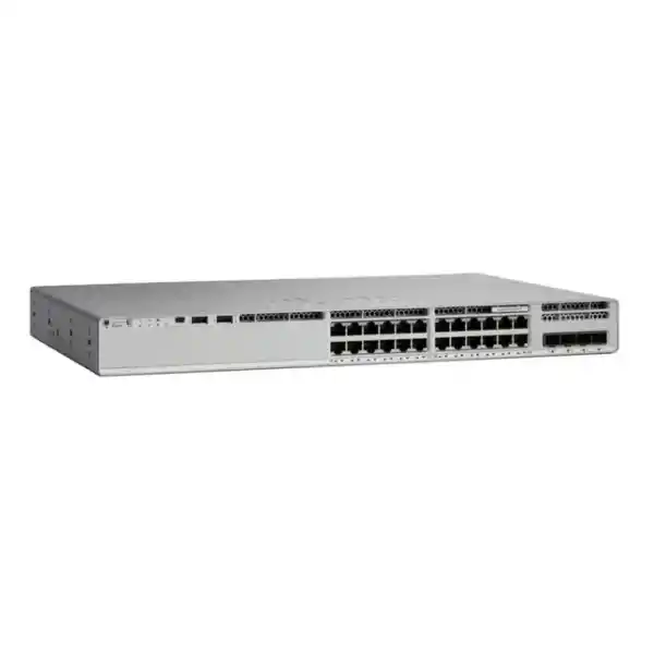
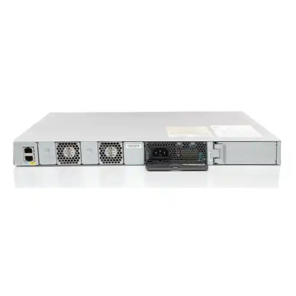
Cisco Catalyst C9200L-24PXG-2Y Network Switch
A multigigabit PoE+ access switch for organizations that need faster wireless edge connectivity, 25Gbps aggregation, Cisco IOS XE operations, and stackable resiliency without moving to a larger chassis platform.
PoE: Full PoE+ access capability
Uplinks: 2 × 1/10/25G fixed
Stacking: StackWise-80
Primary fit: Wi-Fi 6/6E and enterprise access
Direct answer: what is the C9200L-24PXG-2Y designed to do?
The Cisco Catalyst C9200L-24PXG-2Y is a fixed-uplink member of the Catalyst 9200L family built for enterprise access-layer networks where ordinary one-gigabit edge switching is becoming a bottleneck. The front-panel design combines sixteen conventional 1Gbps access ports with eight multigigabit ports that can negotiate at multiple Ethernet rates up to 10Gbps, while all twenty-four access ports are positioned for PoE+ endpoint power. Two fixed uplink ports support 1Gbps, 10Gbps, or 25Gbps operation, creating a practical ratio between high-speed wireless or workstation downlinks and the upstream connection to distribution or core switching.
For a UAE network team, the important point is not simply that this is a 24-port switch. The value is its transition architecture. Many offices still have Cat5e, Cat6, or Cat6A horizontal cabling, a mix of 1G endpoints, and new wireless access points that can exceed one gigabit of aggregate throughput. Replacing every cable plant and every distribution switch at once is often unnecessary. The C9200L-24PXG-2Y allows a network architect to retain ordinary 1G connectivity for printers, phones, cameras, desktops, building controllers, and legacy devices while reserving eight multigigabit copper ports for high-throughput access points, workstations, local servers, or other compatible devices. The two 25G-capable uplinks then provide more headroom than a traditional pair of 10G uplinks when the access layer is heavily utilized.
This model also brings the operational characteristics expected from the Cisco Catalyst 9000 family: Cisco IOS XE software, centralized policy and assurance options, programmable management interfaces, quality-of-service controls, security capabilities, Layer 2 and Layer 3 functions, and StackWise-80 support for joining compatible C9200L units into a single logical stack. The result is an access platform that can serve a compact branch, a floor distribution point, a wireless-heavy office zone, a retail or hospitality site, an education building, or an enterprise wiring closet without requiring an oversized chassis solution.
Verified hardware profile
| Design item | C9200L-24PXG-2Y capability | Planning significance |
|---|---|---|
| Access ports | 24 total: 16 × up-to-1G and 8 × multigigabit up to 10G | Mix standard user endpoints with bandwidth-intensive APs or workstations. |
| PoE capability | Full PoE+ access configuration; 30W-class endpoint design subject to available system PoE budget | Supports converged IP phones, APs, cameras and other PoE/PoE+ devices. |
| Fixed uplinks | 2 × 1/10/25G | Allows migration from 10G to 25G aggregation without replacing the access switch. |
| Standalone switching capacity | 292 Gbps | Provides adequate internal fabric capacity for a high-throughput 24-port edge. |
| Switch capacity with stacking | 372 Gbps | Reflects platform capacity when StackWise connectivity is included. |
| Forwarding rate | 229.16 Mpps standalone; 277 Mpps with stacking | Important for packet-intensive applications and high port utilization. |
| Stacking | StackWise-80, up to 80 Gbps stacking bandwidth; compatible stack design supports up to eight members | Simplifies management and provides resilient multi-switch access blocks. |
| MAC scale | Up to 16,000 MAC addresses for C9200L platform scale | Suitable for enterprise edge segments with substantial endpoint populations. |
| Default AC power supply class | 600W C5 family power supply; two PSU slots | Enables power redundancy and increased PoE budget planning. |
| PoE budget reference | 370W with one 600W AC PSU; up to 740W with two supported 600W AC PSUs | Must be checked against the actual endpoint power draw, not only port count. |
| Chassis dimensions | Approx. 4.4 × 44.5 × 35.0 cm chassis; depth increases with rear components | Fits standard rack deployments while requiring suitable rear clearance and cable management. |
| Weight | Approx. 5.44 kg | Useful for rack loading, shipping and cabinet planning. |
Port architecture: why 16×1G + 8×mGig is a deliberate design
The most useful way to size the C9200L-24PXG-2Y is to divide endpoints by bandwidth class rather than treating all twenty-four ports as identical. The sixteen standard access ports are appropriate for the large installed base of devices that gain little from more than one gigabit: desk phones, ordinary user PCs, printers, badge readers, building-management gateways, many IP cameras, point-of-sale systems, environmental sensors, video-conferencing peripherals, and embedded appliances. Keeping these devices on one-gigabit interfaces avoids consuming premium multigigabit ports where no application benefit exists.
The eight mGig ports are the differentiator. Multigigabit Ethernet is especially relevant to wireless access points because modern radio systems can aggregate traffic beyond a single gigabit even when each individual client remains far below that rate. With compatible cabling and endpoint support, an mGig port can negotiate intermediate Ethernet speeds rather than forcing an all-or-nothing jump from 1G to 10G. This matters in real buildings because structured cabling quality, channel length, connector workmanship, patch panels, and installed cable category can vary significantly. A design that can operate at 2.5G or 5G where 10G is unnecessary or impractical gives the engineer more options than a fixed-speed access layer.
The eight high-speed copper ports can also be used for engineering workstations, local media systems, high-throughput edge compute, NAS appliances, or other devices that support NBASE-T or higher-rate twisted-pair Ethernet. However, the most common enterprise justification remains wireless. When several Wi-Fi 6 or Wi-Fi 6E access points are concentrated in a conference floor, training center, university wing, hospitality property, or dense office, eight multigigabit interfaces create a balanced access block without forcing all twenty-four ports to carry the cost and power characteristics of 10G copper.
For UAE projects, FourTeck recommends documenting an explicit port map during design: which ports serve access points, which serve phones, which serve cameras, which are reserved for growth, and which uplinks connect to the distribution layer. That simple exercise exposes oversubscription, PoE constraints, VLAN requirements, and physical cabling issues before procurement. For broader network design and implementation support, organizations can coordinate switching, routing, wireless, cabling, and operational services through FourTeck IT Services UAE.
25Gbps uplinks: the key reason to select the 2Y variant
The “2Y” portion of the model identity is operationally important because it distinguishes the switch from 9200L variants that use four 10G-class uplinks. The C9200L-24PXG-2Y provides two fixed uplink interfaces capable of 1G, 10G, or 25G operation. For network architects, this changes the uplink design question from “How many 10G links do I need?” to “Should I use a pair of higher-speed links for a simpler, more scalable access block?” A single 25G link can carry more aggregate bandwidth than two 10G links, while dual 25G links can be engineered for redundancy, link aggregation where supported by the topology, or separate upstream paths.
The value becomes clearer when the eight mGig ports are heavily used. If several access points negotiate at 2.5G or 5G, an access switch can produce burst traffic that exceeds the comfortable operating range of a single 10G uplink. Applications such as cloud collaboration, local virtualization, software distribution, video, backup, large file movement, VDI, and high-density wireless onboarding can create synchronized traffic peaks. The 25G uplink option gives the access layer room to grow while still allowing the switch to interoperate at 10G during a phased migration.
A correct 25G design must consider more than interface labels. The distribution switch needs compatible 25G ports; optics or DAC/AOC assemblies must match the physical distance and Cisco support matrix; fiber type and patching must be appropriate; and the selected transceiver should be verified against the intended software release. If the upstream environment only supports 10G today, the C9200L-24PXG-2Y can still be useful because the fixed uplink can run at 10G and later be moved to 25G as the distribution layer is refreshed.
The two-uplink architecture also encourages resilient design discipline. A branch may use one active path and one redundant path; a campus access stack may use distributed uplinks across stack members; or an enterprise may use port-channel techniques to increase availability. The correct choice depends on the spanning-tree, Layer 3 routed access, EtherChannel, first-hop gateway, and distribution architecture. FourTeck can supply the switch as part of a broader UAE network project through FourTeck UAE, with optics, power, stacking and installation items specified as a complete bill of materials rather than as isolated accessories.
Use 10G uplinks when
The existing distribution layer is 10G-only, access traffic is moderate, and the switch is being introduced as part of a phased refresh. Running the uplink at 10G preserves compatibility without preventing a later 25G move.
Use 25G uplinks when
Multiple mGig endpoints are expected to sustain high traffic, the distribution platform is already 25G-ready, or the design calls for higher access-layer headroom without deploying a larger fixed or chassis switch.
PoE+ engineering: calculate watts, not just powered port count
Power over Ethernet is one of the areas where a technically correct switch selection can still fail if the bill of materials is based only on port count. The C9200L-24PXG-2Y can serve PoE+ endpoints across its access interfaces, but the available PoE budget is determined by the installed power-supply configuration. Cisco documentation associates the platform with a 600W AC power-supply class and shows a practical PoE budget of approximately 370W with one supported 600W AC PSU, increasing to approximately 740W when two supported 600W AC supplies are installed in the applicable configuration. The dual-supply design therefore affects both resiliency and total endpoint power capacity.
A common mistake is to multiply twenty-four ports by 30W and assume that the resulting figure must always be available. Real endpoint fleets are more nuanced. A phone may draw only a few watts, a camera may operate below its maximum class most of the time, and an access point may negotiate a higher budget than it consumes continuously. Conversely, some devices may require more power at startup, when radios are fully enabled, when USB peripherals are attached, or when heaters, illuminators, motors, or other accessories activate. The engineering task is to build a worst-case or design-case wattage table using the actual endpoint models.
For example, consider a floor with eight wireless access points at a planned 25W allocation each, eight IP phones at 8W each, four cameras at 15W each, and four ordinary non-PoE user devices. The allocated load is 324W before adding design margin. A single 600W PSU configuration with roughly 370W available for PoE may appear adequate, but the margin is limited once future endpoints, power negotiation differences, and operational policy are considered. Two supplies can provide additional PoE budget and redundancy, but the architect must decide whether the design objective is capacity, N+1 power resilience, or both.
The switch can continue to be a good choice even when not every port needs maximum PoE+. What matters is aligning endpoint requirements with the power budget and redundancy policy. During quotation, list every powered device family and its expected maximum draw. Separate “connected ports” from “powered ports.” Mark devices powered locally so they do not unnecessarily inflate the PoE estimate. Finally, decide whether a power-supply failure must leave all endpoints running or whether noncritical devices can be shed. This is particularly important for voice, physical security, access control, and wireless services, where a switch power event can affect multiple business functions at once.
For racks that combine switching with servers, storage, UPS systems, or edge compute, cabinet power and thermal planning should be treated as one system. Customers building or refreshing such environments can also reference FourTeck Server Dubai for complementary infrastructure planning.
StackWise-80: turning multiple access switches into one operational unit
Cisco C9200L fixed-uplink switches support StackWise-80, which provides up to 80Gbps of stacking bandwidth and allows compatible switches to be joined into a logical stack. Cisco documentation describes support for as many as eight members in a compatible C9200L stack, with stack-member compatibility tied to platform and license-level requirements. From an operator’s perspective, the main benefit is not simply bandwidth between boxes. The value is operational consolidation: a properly designed stack can be configured and monitored as a single system, reducing the number of independent management points in a wiring closet.
Stacking also changes how uplinks can be distributed. Instead of placing every upstream link on one physical switch, an architect can spread uplink connectivity across different stack members so that the loss of a single chassis does not necessarily remove all upstream paths. Endpoints can be distributed in the same way, with important devices connected across multiple members where physical design allows. This does not eliminate the need for correct redundancy protocols, but it gives the access block a more resilient physical foundation than a group of unrelated standalone switches.
The StackWise-80 cables and adapters are not something to assume are included in every quotation. The C9200L stack kit should be considered explicitly in the bill of materials, along with cable length and rack position. Short stack cables can become awkward if switches are separated by patch panels or installed in nonadjacent rack units. Long cables can add cost and clutter. A clean rack elevation should therefore be produced before ordering so that the switch positions, patch panels, cable managers, PSUs, stack connections, console access, uplink optics, and UPS feeds can all be coordinated.
Software consistency is equally important. Stack members should be planned around compatible Cisco IOS XE releases and matching license levels. Before adding a new switch to an installed stack, an engineer should check software compatibility, configuration register behavior, boot mode, and any recommended upgrade procedure. In production environments, stack changes should be covered by a maintenance plan because adding members, changing stack cabling, or upgrading software can affect multiple access-layer devices simultaneously.
A two-switch stack is common for a small resilient access block, while larger wiring closets may use three, four, or more members. The correct stack size is determined by port count, failure-domain preference, rack power, uplink bandwidth, maintenance strategy, and the operational impact of a stack-wide event. Eight-member capability should be viewed as a platform maximum, not as a default design target.
Forwarding architecture and performance headroom
Cisco publishes 292Gbps of standalone switching capacity and a forwarding rate of 229.16 million packets per second for the C9200L-24PXG-2Y. With stacking included in the published platform figures, switching capacity is listed at 372Gbps and forwarding at 277Mpps. These numbers are useful because they show that the switch was not designed merely by adding faster interface labels to an ordinary 1G platform. The internal forwarding resources are sized for a mixed 1G, multigigabit, and high-speed uplink access role.
In practical network design, switching capacity and packet forwarding rate answer different questions. Switching capacity expresses the aggregate bandwidth the switching fabric can handle, while Mpps figures help characterize performance when traffic consists of smaller packets. Voice, telemetry, storage, control-plane exchanges, security systems, application transactions, and internet traffic can all produce packet patterns very different from large sequential file transfers. A sound access-layer platform must therefore handle both aggregate throughput and packet-processing demand.
Catalyst 9200 Series platforms use Cisco’s UADP 2.0 Mini architecture, integrating programmable forwarding capabilities with the system CPU. The practical result is a feature-rich access platform capable of Layer 2 switching, routing functions, access control, QoS, segmentation, telemetry, and other IOS XE services within platform scale. Engineers should still size tables and feature use carefully. Access control lists, routing entries, MAC addresses, QoS policies, multicast state, and segmentation features consume hardware resources. A feature may be supported by software while a specific design scale may still require validation.
For most branch and campus access deployments, the more common bottleneck is not the switch fabric itself but the design around it: oversubscribed uplinks, insufficient PoE budget, slow server or WAN paths, poor Wi-Fi channel planning, endpoint limitations, or old copper cabling. The C9200L-24PXG-2Y addresses the access-switch portion of that equation, but end-to-end performance still requires the distribution, firewall, WAN, wireless, and application infrastructure to be sized consistently.
Layer 2 foundation for enterprise access
At the access layer, the first responsibility of the switch is reliable Ethernet segmentation and loop-free forwarding. The C9200L platform supports the VLAN, trunking, spanning-tree, link aggregation, discovery, and endpoint-edge functions expected in a Cisco enterprise design. The exact configuration should follow a documented campus standard rather than being built ad hoc per port. Typical standards define user VLANs, voice VLANs, wireless management or AP VLANs, camera networks, building-management segments, guest services, infrastructure management, native VLAN policy, trunk allow-lists, and unused-port behavior.
Spanning-tree design deserves particular attention when the switch is deployed as part of a stack or when redundant Layer 2 uplinks are used. Root bridge location, path cost, port priority, edge-port behavior, BPDU Guard, Root Guard, Loop Guard, and EtherChannel design can determine whether a physical fault causes a brief reconvergence or a widespread outage. Many modern campuses reduce Layer 2 domain size by routing closer to the edge, but where Layer 2 access remains appropriate, the control-plane design must still be explicit.
EtherChannel can aggregate multiple compatible links into a logical interface, improving bandwidth utilization and resilience when the upstream topology supports it. With a switch that has two 25G-capable uplinks, a pair of links can provide substantial aggregate capacity. However, link aggregation is not the same as doubling throughput for every individual flow; hash-based load distribution means each conversation typically follows one member link. The design objective is aggregate utilization and fault tolerance across many flows, not a guarantee that one TCP session will consume the sum of both physical links.
Endpoint-facing controls should also be standardized. Auto-negotiation, speed, duplex, PoE policy, voice VLAN assignment, storm control, DHCP snooping trust, port-security or identity policy, logging, interface descriptions, and shutdown rules for unused ports are all easier to manage when implemented from a repeatable template. Cisco IOS XE enables this operational discipline, but the switch will only be as predictable as the configuration standard applied to it.
Layer 3 routing and routed-access considerations
Catalyst 9200 Series software provides Layer 3 capabilities that allow the platform to participate in routed enterprise designs. Cisco identifies support across the family for protocols and functions such as OSPF, EIGRP, IS-IS, RIP, and routed access, with feature availability and scale dependent on software release and license level. This allows the C9200L-24PXG-2Y to do more than operate as a pure Layer 2 edge when the enterprise architecture calls for Layer 3 boundaries closer to users and devices.
Routed access can reduce the size and failure domain of Layer 2 networks by moving routing adjacencies toward the access layer. Instead of stretching user VLANs through multiple closets, an organization can use point-to-point or routed uplinks and terminate local networks in the access block. This can simplify spanning-tree behavior and improve convergence, but it changes gateway placement, routing policy, multicast behavior, IP addressing, first-hop security, and operational procedures. It is therefore an architectural decision, not merely a command-line feature.
License selection matters here. Network Essentials and Network Advantage provide different feature entitlements, and Cisco’s packaging evolves across software generations. A quotation should identify whether the ordering SKU ends in -E or -A and should align that choice with routing, segmentation, automation, and lifecycle requirements. Buying a more capable hardware model does not automatically grant every software feature. Conversely, paying for a higher license tier without a design requirement may add unnecessary cost.
For a branch with a straightforward default route and limited local segmentation, a simpler license and Layer 2/Layer 3 feature set may be sufficient. A campus using advanced routing policy, richer segmentation, or broader Cisco enterprise automation may justify Network Advantage. FourTeck recommends mapping required protocols and functions to Cisco’s current feature matrix before the purchase order is finalized, especially when the switch will integrate with an existing Cisco Catalyst Center, ISE, SD-Access, or routed-campus design.
Security controls at the access edge
The access switch is often the first managed infrastructure device that sees endpoint traffic, so its security role extends well beyond VLAN separation. Catalyst 9200 Series platforms support enterprise access-security mechanisms that can help validate device behavior, restrict unauthorized traffic, protect control protocols, and enforce policy before packets reach upstream firewalls. Cisco also lists MACsec support within the platform family, including AES-128 MACsec capabilities on C9200 models, subject to the applicable interface, feature, software, and licensing requirements.
Common campus controls include 802.1X network access authentication, MAC Authentication Bypass for devices that cannot run supplicants, downloadable or locally configured access policies, DHCP snooping, Dynamic ARP Inspection, IP Source Guard, port-security, protected management access, SNMPv3, authenticated logging, secure SSH administration, and role-based operational procedures. In an identity-based architecture, Cisco ISE can work with the access layer to make authorization decisions based on user, device, posture, location, or other policy context.
Security design must account for nontraditional endpoints. Cameras, printers, IP phones, access-control panels, IoT gateways, smart displays, and building systems may not support modern authentication in the same way as managed corporate laptops. A mature deployment therefore creates endpoint categories and exception processes rather than disabling security controls globally. MAC-based onboarding, profiling, restricted VLANs, static bindings, or dedicated segments can reduce risk while maintaining operability.
The switch should also be hardened as an infrastructure device. Management interfaces should live in a dedicated administrative network or VRF where appropriate. Administrative access should use centralized AAA when available, with local credentials retained only for controlled fallback. Unused services should be disabled. Logging should be sent to a central platform. NTP should be consistent so that events can be correlated. Configuration backups should be automated. Software updates should follow a vulnerability and lifecycle process rather than remaining untouched for years.
The firewall remains essential for north-south and inter-zone policy, but it should not be expected to compensate for an unmanaged access edge. Organizations integrating switching with perimeter and segmentation controls can also review FourTeck Firewall Dubai for complementary security architecture and implementation services.
QoS for voice, video, wireless and business applications
A multigigabit switch can still deliver poor user experience if queues are unmanaged during congestion. Quality of Service is therefore a key part of the C9200L-24PXG-2Y design when the access layer carries IP voice, video meetings, wireless clients, cameras, application transactions, guest internet traffic, backups, and general data over the same infrastructure. The goal is not to make every application “high priority.” The goal is to classify traffic correctly, trust markings only at appropriate boundaries, preserve useful DSCP values, and give latency-sensitive applications predictable treatment when contention occurs.
Voice traffic is commonly given expedited treatment because jitter and packet loss are immediately noticeable. Interactive video also benefits from controlled latency, but giving video unlimited priority can starve other applications. Wireless traffic is more complicated because an AP may tunnel or locally switch many user classes through one multigigabit interface. The switch port therefore sees aggregated traffic from multiple users and applications, making trust boundaries and queuing policy especially important.
The 25G uplinks reduce the likelihood of congestion between access and distribution, but they do not eliminate the need for QoS. Congestion can still occur farther upstream at a WAN circuit, firewall, internet edge, cloud interconnect, or server interface. Consistent end-to-end classification allows those devices to make intelligent forwarding decisions. A QoS policy should therefore be documented across the whole path instead of configured differently on each switch.
During migration, engineers should inventory existing trust settings and policy maps before replacing legacy Catalyst switches. A new platform may support more modern policy syntax or different defaults. Copying old commands line for line without understanding the intended traffic model can produce unexpected results. The safer approach is to translate business requirements—voice quality, conferencing, critical transactional traffic, bulk transfers, guest traffic—into a current IOS XE QoS design and validate it with interface counters and application testing.
Cisco IOS XE operations, automation and observability
Cisco IOS XE is central to the operating model of the Catalyst 9200L family. For teams accustomed to traditional Cisco CLI workflows, familiar configuration and show commands remain important. At the same time, modern IOS XE releases expose structured management and automation mechanisms that can reduce repetitive manual work. Depending on the release and enterprise tooling, organizations can use model-driven APIs, NETCONF/RESTCONF, telemetry, automation platforms, templates, and centralized management to deploy and monitor the access layer at scale.
The operational decision is not “CLI versus automation.” Most mature teams use both. CLI remains valuable for troubleshooting, emergency access, validation, and low-level visibility. Automation is valuable for standardization, configuration generation, compliance checks, inventory, upgrades, and large-scale changes. A switch such as the C9200L-24PXG-2Y becomes significantly easier to manage when interface descriptions, VLAN assignments, AAA, NTP, SNMP, logging, QoS, security controls, and routing templates are generated from approved standards rather than typed individually on every device.
Cisco also positions the Catalyst 9200 family for integration with Cisco Catalyst Center and provides cloud-monitoring options for Catalyst through the Meraki dashboard for applicable models and software. These management choices allow organizations to select a control model appropriate to their estate. A fully centralized campus may use Catalyst Center for automation, assurance, inventory and policy. A smaller environment may prefer traditional CLI plus network management software. A distributed enterprise may value cloud visibility. The hardware does not force one operational style, but licensing and software requirements should be verified for the selected management approach.
Observability is particularly valuable for multigigabit ports because interface speed alone does not prove that an endpoint is healthy. Engineers should monitor negotiated speed, duplex, PoE draw, errors, discards, queue drops, link flaps, temperature, CPU, memory, uplink utilization, stack status, spanning-tree events, security violations, and transceiver health. Trend data can reveal a cable that only negotiates at 1G when 5G was expected, an AP that frequently reboots due to power issues, or an uplink that consistently approaches saturation during business peaks.
Operational readiness should be considered part of deployment. The switch should enter production with a monitoring template, backup process, naming standard, asset record, software baseline, configuration archive, and documented recovery method. This reduces the risk that a well-specified piece of hardware becomes an unmanaged point of failure after handover.
Network Essentials vs Network Advantage: order the right software level
The base model name C9200L-24PXG-2Y identifies the hardware family, but Cisco ordering commonly distinguishes Network Essentials and Network Advantage variants with suffixes such as -E and -A. Cisco’s current ordering information lists both C9200L-24PXG-2Y-E and C9200L-24PXG-2Y-A. This distinction should appear in the quotation because the software tier affects which network functions are licensed and what future design options remain available.
Network Essentials is often appropriate for straightforward enterprise access where the design relies primarily on core Layer 2 functions, common routing capabilities, standard security controls, and conventional access switching. Network Advantage is intended for organizations that require a broader advanced feature set. The exact Cisco feature matrix can change across software releases, so the correct method is to list the required features first and map them to the current entitlement rather than selecting a tier by habit.
Subscription components associated with Cisco’s enterprise networking software should also be reviewed at the time of purchase. Hardware procurement, perpetual network entitlements where applicable, subscription terms, support coverage, and management-platform licensing are related but distinct commercial elements. An organization should know what it owns, what expires, what is needed for software download access, what supports centralized management, and what is required for advanced functionality.
For lifecycle planning, the better question is not “What is the cheapest license today?” but “What features will this access block need during its expected service life?” A switch installed in 2026 may remain in service through multiple wireless refreshes, security changes, routing redesigns, and management-platform upgrades. If there is a realistic probability of advanced segmentation or routing being introduced, selecting the appropriate entitlement at procurement can reduce friction later. If the network will remain a simple branch access layer, a higher tier may not be justified.
FourTeck quotations can therefore be structured to show hardware, license tier, required software subscription term, support, optics, stack accessories, second PSU, installation and configuration as separate line items. This makes commercial comparison easier and prevents hidden scope gaps between competing offers.
Redundancy: power, stack, uplink and operational failure domains
High availability at the access layer is built from several independent mechanisms. The C9200L-24PXG-2Y provides two power-supply slots, enabling designs that use dual supported supplies. This can improve resilience if the supplies are fed from genuinely independent power paths. Plugging both PSUs into the same single PDU or UPS improves protection against an individual PSU failure but does not protect against loss of that shared power source. A stronger design uses separate UPS outputs or A/B power distribution where available.
Stacking addresses a different failure domain. Two or more switches connected through StackWise-80 can operate as one logical system, but each physical chassis remains a potential point of hardware failure. Important endpoints can be distributed across stack members so that one failed chassis does not remove every AP, phone, or camera in a zone. Uplink interfaces can also be spread across members, reducing dependence on a single box for upstream connectivity.
The uplink network is the next layer of resilience. A pair of 25G-capable interfaces can connect to redundant upstream devices when the topology and protocols support it. Whether those links operate as a port channel, routed links, or another design depends on the distribution architecture. Redundancy should be tested rather than assumed. During commissioning, engineers should simulate loss of one uplink, one PSU, one stack member where safe, and one upstream path to confirm convergence behavior and application impact.
Operational failures deserve equal attention. An incorrect configuration, failed software upgrade, misapplied automation template, expired credential, or unauthorized change can affect a perfectly healthy switch. Configuration archives, change control, role-based access, out-of-band console options, standard images, tested rollback plans, and current support coverage reduce these risks. In a stacked environment, the blast radius of a mistake can be larger because several physical switches share one logical control plane.
For critical UAE facilities, resilience requirements should be written in measurable terms: maximum acceptable outage, number of endpoint failures tolerated, required PoE continuity, uplink recovery time, maintenance windows, spare hardware strategy, and support response expectation. These requirements then drive whether one switch, a two-member stack, dual power, redundant uplinks, or a higher-tier architecture is justified.
Wireless-first design for Wi-Fi 6 and Wi-Fi 6E
The C9200L-24PXG-2Y is particularly compelling when an organization is upgrading the wireless layer faster than the wired edge. Wi-Fi 6 and Wi-Fi 6E access points can support aggregate radio capacity that makes a one-gigabit wired connection a potential constraint, especially in dense client environments. Eight multigigabit ports allow selected APs to connect above 1G while the remaining sixteen ports continue serving conventional endpoints efficiently.
A wireless-first switch design should start with the AP model and radio plan. Determine the maximum Ethernet speed supported by each AP, its PoE requirement, whether it uses one or multiple Ethernet interfaces, and whether special features change power draw. Then map AP locations to the wiring closet. Eight mGig ports may be ideal for one floor, but a large building with more than eight high-throughput APs per closet may require multiple switches or a different port-density model.
Cabling matters. A link that supported 1G for years may not automatically deliver stable 5G or 10G operation. Cable category, installed channel length, bend radius, termination quality, patch cords, electromagnetic environment, and historical damage all influence higher-speed copper performance. A wireless upgrade should therefore include copper certification or at least targeted testing for AP runs expected to operate above 1G. Where cable replacement is practical, Cat6A is commonly preferred for the most demanding 10G twisted-pair designs and future growth.
The uplink design must then be checked against aggregate wireless throughput. Eight APs do not each transmit at their wired link rate continuously, so theoretical sum-of-port speeds should not be interpreted as expected traffic. Still, a dense office can produce substantial bursts. Moving the uplink from 10G to 25G can provide useful headroom and reduce the chance that a successful wireless upgrade simply shifts the bottleneck to the access-distribution connection.
Finally, wireless management, guest traffic, corporate SSIDs, voice, IoT and location services may have different VLAN, QoS and security requirements. The switch configuration should be built together with the wireless design so that AP trunking, native VLANs, PoE settings, mGig negotiation, QoS trust, DHCP, DNS, authentication and upstream firewall policy all align.
Physical installation in UAE racks and telecommunications rooms
The chassis is approximately 1RU high, 44.5cm wide and 35cm deep before accounting for rear components, power leads, stack cables and bend radius. Cisco documentation lists the unit at approximately 5.44kg. These measurements fit ordinary enterprise rack environments, but depth planning should include rear clearance and the additional projection of power and stack connections. A crowded wall cabinet that technically accepts a 1RU switch may still be unsuitable if doors cannot close or cables are forced into tight bends.
Thermal management is especially important in the Gulf. The switch should be installed in an air-conditioned telecommunications space within Cisco’s environmental specifications, with airflow paths kept clear. It should not be treated as a rugged outdoor device merely because the network serves outdoor cameras or access points. Dust accumulation, blocked vents, failed room cooling, overloaded cabinets and poorly managed power can significantly reduce reliability. The best network design includes temperature monitoring and facility escalation procedures for communication rooms.
Rack layout should minimize service complexity. Patch panels are ideally arranged so that endpoint patch leads do not cross large areas of the cabinet. Stack members should be positioned to suit the selected stack cable lengths. Uplink fiber should have protected routing and appropriate slack management. A/B power cords should be clearly labeled. Console and management access should remain reachable after all cables are installed. Asset labels should identify hostname, management IP, rack, unit position, serial number and support details according to the customer’s standard.
Power calculations should include not only switch input but also PoE output. A switch serving many powered endpoints can draw substantially more energy than an idle data-only switch. UPS sizing should be based on realistic maximum load and required runtime. If the site expects thirty or sixty minutes of network continuity during utility interruption, the UPS must support the full switch-plus-PoE load for that duration, not just the chassis base consumption.
For new builds, structured cabling acceptance tests should be retained with as-built documentation. For upgrades, ports assigned to 5G or 10G endpoints should be tested specifically. This makes it easier to distinguish a cabling fault from a switch or endpoint problem when a multigigabit port negotiates below the expected rate.
Deployment topology 1: resilient enterprise floor
A common use case is a corporate floor with six to eight high-capacity wireless access points, IP phones, fixed workstations, meeting-room systems and several security devices. Two C9200L-24PXG-2Y switches can be installed as a StackWise-80 pair. Access points are distributed across the mGig ports on both members, while ordinary desktops and phones occupy the 1G ports. Dual 25G uplinks are distributed across the stack toward redundant distribution switches where the architecture supports that design.
This topology provides several advantages. The access block can be managed as one logical stack, endpoints can be balanced between physical chassis, and the uplink design can avoid dependence on one member. If dual PSUs are used, the switches can also be connected to separate power sources. The architecture does not make the floor immune to failure, but it removes several single points of failure that exist in a standalone one-switch design.
The final port and power map should reserve capacity for growth. If all sixteen mGig ports across a two-switch stack are occupied on day one, future AP additions may require another stack member. A better design may intentionally leave two to four mGig ports free, particularly in offices where wireless density is expected to increase.
Deployment topology 2: high-performance branch
A branch office with local servers or edge appliances may use the switch as a compact converged access platform. Standard employees connect at 1G, selected engineering or creative workstations use 2.5G, 5G or 10G where endpoint NICs support it, and wireless APs occupy the remaining mGig ports. One 25G uplink can connect to a capable branch core, with the second retained for redundancy or future use.
The limitation in this topology may be the WAN or firewall rather than the switch. A 25G campus uplink does not accelerate a 1G internet circuit. However, local east-west traffic—backups, file services, imaging, virtualization, local analytics or software distribution—can benefit from a faster access-distribution path. This is especially relevant for branches that function as small regional hubs rather than simple satellite offices.
When the branch firewall is materially slower than the access layer, traffic paths should be reviewed carefully. Inter-VLAN routing placed on the firewall can force local traffic through that bottleneck, while routed switching may keep appropriate traffic inside the campus. The correct placement depends on security policy, segmentation requirements, firewall capacity and inspection needs.
Deployment topology 3: wireless-dense education, hospitality or training space
Education campuses, hotels, conference facilities and training environments often have a high ratio of wireless clients to wired desks. In these scenarios, the eight mGig ports can be dedicated primarily to access points while the sixteen 1G ports support local operational devices such as phones, cameras, room systems, access control, signage and administration endpoints. The design keeps premium multigigabit interfaces focused on traffic sources that can actually use them.
PoE sizing becomes central because APs and cameras may represent the majority of connected devices. The engineer should use the actual AP and camera power requirements to determine whether one 600W PSU provides sufficient PoE budget and whether the second supply is needed for capacity, resilience or both. High availability may be particularly important in hospitality and education because one wiring-closet failure can affect many rooms, classrooms or public areas simultaneously.
Guest wireless also increases the importance of segmentation and QoS. User onboarding, captive portals, identity systems, DHCP, DNS and firewall policy should be designed as an end-to-end service. The switch provides the access foundation, but the user experience depends on the wireless controller or management platform, authentication services, internet capacity and security architecture.
How the C9200L-24PXG-2Y compares with nearby Catalyst options
| Model direction | Best reason to choose it | Trade-off versus C9200L-24PXG-2Y |
|---|---|---|
| C9200L-24PXG-2Y | Need 8 mGig PoE+ ports and a pair of 25G-capable fixed uplinks. | Only two fixed uplink interfaces; fans are fixed on C9200L platform. |
| C9200L-24PXG-4X | Prefer four 10G-class fixed uplinks for topology or port-count reasons. | Does not offer the same two-port 25G uplink profile. |
| C9200-24PXG | Need modular uplink flexibility, StackWise-160 and field-replaceable fan architecture. | Typically a higher-feature and potentially higher-cost platform than 9200L. |
| Conventional 1G C9200L PoE+ models | Most endpoints are 1G and there is no meaningful mGig requirement. | Less future headroom for high-speed APs and multigigabit copper devices. |
The C9200L-24PXG-2Y is therefore most compelling when both sides of the access layer need modernization: faster copper downlinks for selected endpoints and faster fiber or DAC uplinks toward distribution. If only one of those requirements exists, another Catalyst variant may be more economical.
Migration from older Catalyst access switches
Replacing an older Catalyst 2960, 3650, 3750, 3850 or previous-generation access switch should be treated as a migration project rather than a simple hardware swap. The new platform may use different interface naming, software packaging, stacking hardware, power supplies, optics compatibility, feature syntax and default behavior. A successful migration starts by extracting the operational intent from the existing configuration instead of blindly copying every command.
Inventory VLANs, trunks, EtherChannels, spanning-tree settings, routed interfaces, ACLs, QoS policies, DHCP snooping, voice VLANs, SNMP, AAA, logging, NTP, NetFlow or telemetry, multicast features, static routes, routing protocols, port descriptions and administrative shutdown states. Identify commands that were historical workarounds rather than current requirements. Review whether unused VLANs and ports can be removed. Confirm the current default gateway and management path. Document any dependencies on old software behavior.
Physical migration needs similar discipline. Check whether existing SFP/SFP+ optics are supported in the C9200L-24PXG-2Y and whether 25G optics are required. Confirm fiber connector type and patching. Verify that existing power cords, PDUs and UPS capacity are appropriate. If the old switch uses a different stacking technology, new stack kits and cables will be required. Measure rack depth and cable reach before the maintenance window.
A staged migration can reduce risk. Preconfigure management, VLANs, authentication, routing and uplinks; load the approved IOS XE release; validate licenses; test console access; label cables; and create a port-by-port cross-reference from old interface to new interface. During cutover, move uplinks first or according to the approved method, then migrate endpoint groups in a controlled order. Validate DHCP, DNS, authentication, voice registration, wireless AP status, camera feeds, critical applications and monitoring before declaring success.
Rollback planning is essential. Keep the old switch configuration and physical unit available until the new environment passes acceptance. Define a time by which the team will revert if core services are not stable. A rollback plan does not indicate lack of confidence; it is standard engineering practice for minimizing business impact.
UAE procurement and lifecycle planning
Enterprise switch procurement in the UAE should consider the complete lifecycle rather than only the chassis price. The hardware model, software entitlement, subscription term, support coverage, power supplies, power cords, stack kits, stack cables, rack accessories, uplink transceivers, fiber or DAC assemblies, spares, installation, configuration, documentation and testing can all affect total project cost. Two quotations that show the same base switch may therefore represent very different deployable solutions.
The C9200L-24PXG-2Y base identifier should be translated into the correct orderable license SKU. If Network Essentials is appropriate, the -E ordering variant may be selected; if Network Advantage is required, the -A variant may be selected. The selected Cisco software subscription and support program should be shown clearly. If the project expects 25G uplinks, the exact transceiver or cable type should appear in the bill of materials rather than being left as “uplink optics.”
Lead time can matter on enterprise networking projects, especially when multiple switches, specific optics, or accessories are required. A project plan should separate items that are critical to first-site deployment from items that can arrive later. Receiving inspection should verify model numbers, power supplies, accessories, serial numbers and packaging condition before installation teams are scheduled. For multi-site deployments, asset details should be captured into a central inventory from the beginning.
Support entitlement is equally important. Access switches often remain in service for many years, and software defects, security vulnerabilities, hardware failures and compatibility changes can arise during that lifetime. The organization should understand its replacement process, software download rights, escalation path and spare strategy. A critical site may keep an on-site spare or use a service level with faster replacement; a less critical office may accept a different recovery model.
For organizations that operate across the Middle East and Africa, standardizing on a small number of approved access-switch profiles can simplify spares, templates and training. FourTeck also supports broader regional technology requirements through FourTeck Africa, helping enterprises align product selection and deployment standards across distributed sites.
The practical procurement objective is therefore a “ready-to-install” bill of materials. Every dependency required to rack, power, stack, uplink, license, manage and support the switch should be visible before purchase approval.
Recommended bill-of-materials logic
1. Core switch SKU
Select C9200L-24PXG-2Y with the required Network Essentials or Network Advantage ordering suffix.
2. Software term
Match Cisco software subscription and management requirements to the customer’s lifecycle and feature plan.
3. Power design
Confirm whether one or two supported PSUs are required and calculate the endpoint PoE budget with margin.
4. Stack components
Add C9200L StackWise hardware and suitable cable lengths if two or more switches will operate as a stack.
5. Uplink media
Specify 10G or 25G optics, DAC or AOC based on distance, fiber type, distribution platform and Cisco compatibility.
6. Services and support
Include installation, migration, testing, documentation, support coverage and spares where project risk requires them.
Commissioning checklist for network engineers
Before production traffic is moved, confirm the switch is running the approved Cisco IOS XE release and that the boot process, license state and hardware inventory are normal. Record the serial number, product identifier, software version, hostname, management address and stack member identifiers. Validate that the intended primary and secondary stack roles are stable where stacking is used. Check that both power supplies are recognized if dual power is installed and that PoE capacity matches the design.
Validate every uplink at the expected speed. A port intended for 25G should actually negotiate or operate at 25G; do not assume this from configuration alone. Check transceiver diagnostics where available, interface errors, light levels for optical links, EtherChannel state, spanning-tree role, routing adjacency and MTU settings. Where redundant links exist, perform controlled failover tests and record convergence behavior.
For access ports, test representative endpoint categories. A wireless AP should negotiate the intended mGig rate and obtain the expected PoE allocation. A phone should join the correct voice VLAN and register. A corporate workstation should authenticate and receive the correct data-network policy. A camera should power up and reach its management or recording platform. A guest or unmanaged device should receive only the access permitted by policy.
Security controls should be tested with both positive and negative cases. Confirm that unauthorized DHCP servers are blocked if DHCP snooping is used, that access authentication behaves correctly when identity services are unavailable, and that management access is restricted to approved sources. Verify that logs reach the monitoring platform and that NTP is synchronized so timestamps are trustworthy.
Finally, create a baseline. Save interface utilization, error counters, PoE consumption, temperature, CPU, memory, stack status and uplink statistics shortly after commissioning. This baseline gives operations teams a reference when troubleshooting later and can reveal whether the production traffic profile differs materially from design assumptions.
Design limitations and cases where another switch may be better
The C9200L-24PXG-2Y is not the correct platform for every environment. The uplinks are fixed rather than modular, so organizations that need to change between a wider range of uplink module types may prefer a modular C9200 model. The C9200L family uses StackWise-80 rather than the higher StackWise-160 bandwidth available on modular C9200 models. C9200L fans are fixed rather than field-replaceable, which may matter to organizations that prioritize maximum serviceability.
The switch provides eight mGig ports, not twenty-four. A design that expects every user port to operate at 2.5G, 5G or 10G should consider a different port-density profile. Similarly, a site requiring PoE capabilities above standard PoE+ on many ports may need a platform designed for higher-power IEEE 802.3bt or Cisco UPOE endpoint requirements. Always match the endpoint power class, not just “PoE yes/no.”
Two 25G uplinks are powerful, but some topologies benefit more from four 10G uplinks. For example, a design may require physical connections to several upstream or service devices rather than maximum bandwidth per link. The C9200L-24PXG-4X may fit those cases better. Conversely, organizations that need 40G modular uplinks, broader virtual-network scale, or higher stacking bandwidth may be better served by modular C9200 or higher Catalyst families.
The platform should also not be positioned as a data-center top-of-rack switch. Although it provides high-speed access and 25G uplinks, its feature set and architecture are optimized for campus and branch access. Data-center switching may require different buffering, latency, airflow, EVPN/VXLAN, storage-network functions, port densities, automation workflows and high-speed interface profiles.
A good quotation therefore includes a fit assessment, not only a price. If the customer’s requirements exceed the natural design envelope of the C9200L-24PXG-2Y, selecting a different model early is less expensive than discovering the limitation after deployment.
Sizing methodology: a repeatable way to validate this model
Step one is endpoint inventory. Count wired users, phones, cameras, APs, printers, IoT devices, servers, uplinked mini-switches and any special systems. Assign each endpoint a required link speed and expected PoE draw. Mark ports that require 2.5G, 5G or 10G separately from ordinary 1G ports. This immediately shows whether eight mGig interfaces are sufficient.
Step two is growth allowance. Do not size the switch to use every port on installation day unless space, cost or architecture requires it. Reserve ports for added APs, desk moves, cameras, temporary devices and troubleshooting. In rapidly changing offices, 15–25 percent spare access capacity is often operationally useful, though the exact margin should match the customer’s planning horizon.
Step three is PoE budgeting. Sum the design allocation for powered endpoints and compare it with the PSU configuration. Add margin for device replacement and feature changes. If one PSU provides enough normal operating power but not enough capacity after a PSU failure, decide whether that is acceptable. Power resilience should be a stated business requirement rather than an accidental outcome.
Step four is uplink sizing. Estimate aggregate traffic from access points, users and local services. Consider whether traffic is primarily internet-bound, local server traffic, inter-VLAN traffic, backup, media or cloud collaboration. Check the upstream distribution interface capacity. Select 10G initially if appropriate, but use 25G where the traffic model or growth plan justifies it.
Step five is feature and license validation. List every required routing protocol, security feature, segmentation function, management platform and automation dependency. Map those requirements to Network Essentials or Network Advantage and the relevant software subscription. Verify that planned features are supported on the intended IOS XE release.
Step six is resilience. Determine whether one switch is acceptable or whether a StackWise pair or larger stack is required. Decide on dual PSUs, redundant uplinks, separate power feeds and spare strategy. Model the effect of losing a switch, a PSU, an uplink, a stack cable, an upstream distribution device and the management platform.
Step seven is physical validation. Confirm rack depth, RU space, cooling, UPS capacity, cable reach, fiber type, patch-panel layout and access to the rear of the switch. A design that works on a network diagram can still fail during installation if the cabinet or cabling does not support it.
Operational best practices after deployment
Once the switch is in service, treat configuration drift as a measurable risk. Maintain a golden configuration standard for management access, logging, NTP, SNMP, AAA, banner, DNS, spanning tree, security controls and interface templates. Periodically compare production configuration against that baseline. Unauthorized or undocumented changes are easier to correct when detected quickly rather than during an outage months later.
Monitor mGig ports for negotiated speed and physical-layer errors. A port expected to run at 5G that repeatedly falls back to 1G may indicate cabling or endpoint issues. Track PoE consumption and denied-power events. Watch uplink utilization across business cycles rather than relying on a single snapshot. If a 10G uplink consistently approaches high utilization, the 25G capability of the 2Y variant provides a straightforward upgrade path when the upstream switch is ready.
Software lifecycle should be planned. Select stable IOS XE trains appropriate to the enterprise, review Cisco advisories, test upgrades in a representative environment where possible, back up configuration and images, and schedule maintenance with rollback procedures. Stacked access switches need additional attention because a software event can affect many physical ports at once. Verify stack health before and after any upgrade.
Keep support and inventory data current. Serial numbers, installation dates, rack positions, power-supply identifiers, optics, stack topology and license details should be recorded. When hardware replacement is required, accurate records reduce troubleshooting and RMA delays. For multi-site organizations, use consistent hostnames and location codes so that monitoring alerts clearly identify the affected physical site.
Capacity reviews should be performed periodically. A switch that was correctly sized when installed may later gain more APs, cameras or users. Reviewing free ports, mGig availability, PoE headroom, stack member count, uplink utilization and error rates helps operations teams plan upgrades before service quality degrades.
Decision recap: when this switch is the right choice
Choose it for mGig access
You need up to eight high-speed copper ports for Wi-Fi 6/6E APs or selected workstations while preserving sixteen cost-efficient 1G ports.
Choose it for 25G aggregation
Your distribution layer supports, or is expected to support, 25G and you want more uplink headroom than conventional 10G access designs.
Choose it for PoE convergence
Phones, access points, cameras and other powered endpoints should share a managed enterprise access platform with a calculated PoE budget.
Choose it for stackable operations
You want StackWise-80, multi-switch logical management and resilient access-block designs without moving to a chassis platform.
Quotation input checklist
For an accurate UAE quotation, provide the information below. These inputs allow the switch, license, power, optics and stack accessories to be sized as one solution rather than as separate guesses.
Number of switches, Dubai/Abu Dhabi/other UAE location, and whether units are for one site or several branches.
Network Essentials or Network Advantage, plus any required Cisco software subscription term.
AP, phone, camera and IoT model counts with maximum or design PoE wattage.
How many devices require 2.5G, 5G or 10G copper and what cable category is installed.
10G or 25G, fiber/DAC/AOC preference, distance, connector type and upstream switch model.
Standalone, two-member stack or larger stack, plus rack layout and preferred stack cable lengths.
Single or dual PSU, A/B power availability, UPS runtime target and required PoE continuity during a PSU failure.
Supply only, rack-and-stack, migration, configuration, testing, documentation, training or managed support.
FourTeck consultation for Cisco Catalyst C9200L-24PXG-2Y in UAE
The C9200L-24PXG-2Y is strongest when it is purchased as part of a complete access-layer design: correct -E or -A license variant, appropriate Cisco software term, sufficient PoE budget, supported 10G/25G uplink media, StackWise-80 hardware where required, and a migration plan that accounts for existing VLANs, routing, security and wireless services.
FourTeck can help UAE customers validate the switch against endpoint count, Wi-Fi 6/6E density, distribution-switch capability, rack power, cabling, resiliency and support requirements. This avoids the most common procurement gaps—missing second PSU, incorrect optics, insufficient PoE capacity, wrong license tier, incompatible stack assumptions or an uplink that cannot operate at the intended 25G speed.
Share the current switch model, target endpoint mix, uplink architecture and desired redundancy level. The resulting bill of materials can be structured for supply-only or for full implementation, testing and handover.

Reviews
There are no reviews yet.