
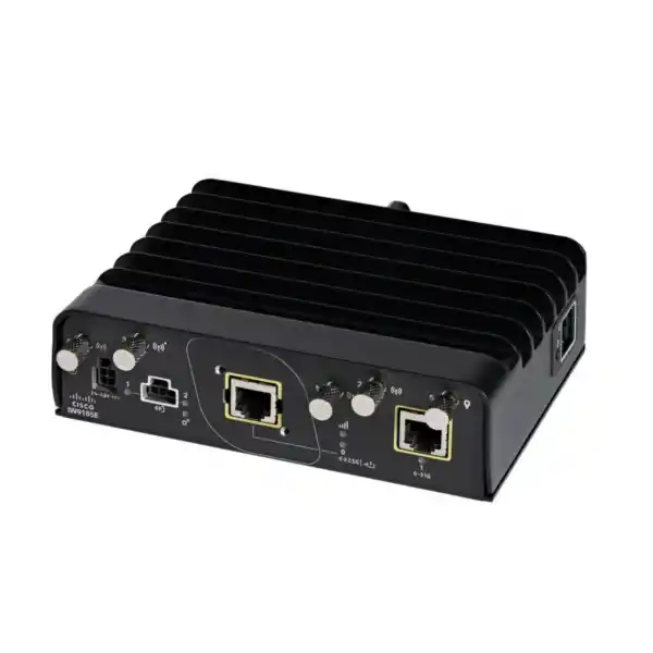
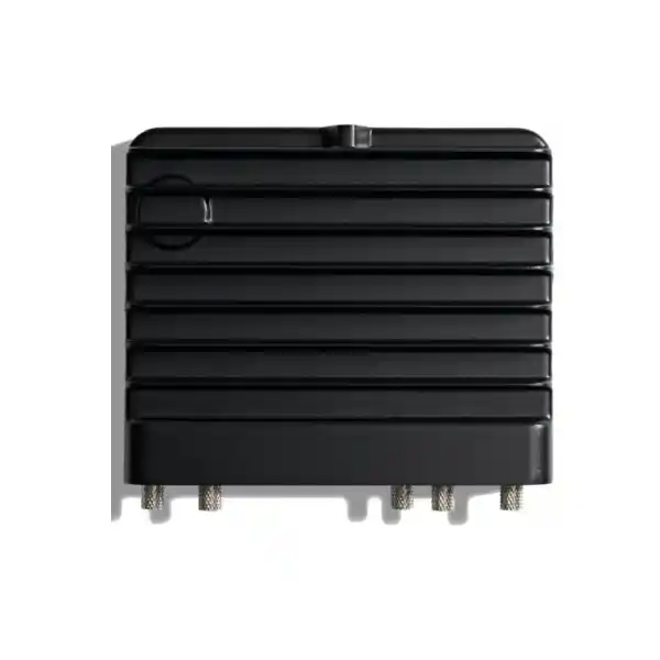
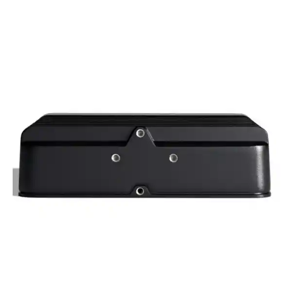
Cisco Catalyst IW9165E Industrial Access Point
A compact, rugged industrial wireless platform for factories, automated warehouses, AGV and AMR fleets, transportation systems, industrial cabinets, moving assets, and mission-critical connectivity where ordinary enterprise access points are not designed to operate. The Cisco Catalyst IW9165E combines dual 2×2 radios, Wi-Fi 6/6E operation, Cisco Ultra-Reliable Wireless Backhaul, Workgroup Bridge functionality, external antenna flexibility, multigigabit Ethernet, PoE and DC power options, DIN-rail mounting, and an extended industrial temperature range.
Correct regulatory domain, software personality, antennas, coax assemblies, power source, mounting, controller or URWB architecture, roaming requirements, RF survey and environmental protection should be confirmed together before ordering.
Wireless architecture
Two 2×2 radios: one 5 GHz radio and one 5/6 GHz radio, with Wi-Fi 6/6E support according to software, regulatory domain and country approvals.
Industrial mobility
Designed for moving machines and vehicles through WGB, Universal WGB and Cisco URWB deployment models, including AGV and AMR connectivity.
Rugged installation
IP30 enclosure, wall/panel or DIN-rail mounting, -40°C to +70°C operation in still air, and industrial power options.
Flexible interfaces
2.5GbE multigigabit PoE input, secondary Gigabit Ethernet, four RP-SMA RF ports, GNSS antenna port, GPIO, console and DC input.
What is the Cisco Catalyst IW9165E?
The Cisco Catalyst IW9165E is an industrial wireless access point and wireless client built for applications where wireless is part of the operational infrastructure rather than simply a convenience service for laptops and phones. In a conventional office WLAN, an access point is normally mounted on a ceiling, remains stationary, operates in a controlled indoor climate, and primarily serves user devices. Industrial wireless has different priorities. An access point may be installed inside an electrical cabinet, attached to a moving vehicle, mounted in a production area, connected to programmable controllers, machine vision systems or safety-adjacent control networks, and expected to maintain connectivity as equipment moves between coverage zones. The IW9165E is designed around those conditions.
Cisco positions the IW9165E as a compact rugged access point and wireless client that can operate in multiple software roles. Depending on the ordered software personality and deployment design, it can function as a Wi-Fi access point, as a Workgroup Bridge client connected to a Cisco wireless infrastructure, as a Universal Workgroup Bridge that can connect to compatible third-party Wi-Fi infrastructure, as a Cisco Ultra-Reliable Wireless Backhaul node, or in supported combinations that allow URWB and Wi-Fi access functionality to coexist. This flexibility is important for industrial organizations because the same hardware family can support fixed coverage, mobile asset connectivity and resilient wireless backhaul without forcing every project into a traditional office-WLAN model.
For UAE organizations, the value of the IW9165E is not merely its radio specification. The platform is useful when the deployment requires deliberate engineering around heat, metal-rich environments, mobile handoffs, external antennas, industrial power, cabinet mounting, network segmentation and long lifecycle operations. FourTeck can support this process from requirement analysis through supply, controller and licensing alignment, antenna selection, network integration and site rollout. Customers planning wider enterprise connectivity can also review FourTeck UAE for complementary networking and infrastructure services.
Direct answer: who should consider the IW9165E?
Factories and process plants
Use the platform where industrial clients, machine controllers, robots and production assets require robust wireless access in areas with metal structures, electrical cabinets, challenging RF reflections and strict uptime expectations.
AGV and AMR fleets
The compact enclosure, DIN-rail options, WGB/uWGB modes and URWB capability make it relevant for mobile robots and automated guided vehicles that need Ethernet-connected onboard devices to remain networked while moving.
Rail and transport systems
M12 connectivity options and industrial certifications such as EN50155 support transportation designs where vibration, mounting constraints, power design and reliable handoff behavior are significant engineering considerations.
Industrial wireless backhaul
URWB can be used where cable or fiber is difficult, disruptive or uneconomic, especially when high-priority traffic requires deterministic behavior, path diversity and fast mobility across a designed industrial wireless fabric.
Radio architecture and Wi-Fi 6/6E capability
The IW9165E uses two 2×2 radios. One radio operates in the 5 GHz band and supports 20, 40 and 80 MHz channels. The second radio can operate in 5 GHz or 6 GHz and supports 20, 40, 80 and, where applicable, 160 MHz channels. This architecture is deliberately different from many enterprise access points that provide simultaneous 2.4 GHz, 5 GHz and 6 GHz radios for broad client compatibility. The IW9165E concentrates on industrial use cases in the 5 GHz and 6 GHz spectrum, where more channel capacity and less dependence on legacy 2.4 GHz clients can be advantageous. Before selecting the product, engineers should confirm that the industrial clients, scanners, onboard controllers and embedded Wi-Fi modules involved in the project support the intended bands.
Wi-Fi 6, based on IEEE 802.11ax, improves spectral efficiency through mechanisms such as OFDMA, improved scheduling and more effective multi-user operation. In industrial environments these features are useful not simply because they can increase peak throughput, but because they allow airtime to be used more efficiently when many clients share the same channel. The IW9165E supports 802.11ax modulation and coding rates up to MCS 11 with one or two spatial streams, subject to channel conditions, regulatory limits and client capability. The 5/6 GHz radio can support channels up to 160 MHz, although an industrial design should not automatically choose the widest possible channel. Wider channels can increase peak PHY rate but reduce the number of non-overlapping channels available for reuse and may be more vulnerable to interference. Dense factories often benefit from 20 or 40 MHz channels, while selected backhaul or lower-density use cases may justify 80 or 160 MHz after survey and spectrum analysis.
Wi-Fi 6E extends 802.11ax operation into the 6 GHz band. The engineering benefit is access to additional spectrum and a cleaner RF environment because legacy pre-Wi-Fi 6E devices do not operate there. However, 6 GHz operation is country and regulatory-domain dependent. UAE deployments must be validated against the applicable regulatory approvals, the exact Cisco regulatory domain being ordered, approved power classes, permitted channel use and the antenna system. FourTeck recommends treating 6 GHz as a designed capability, not an assumption. The bill of materials should be frozen only after the project team confirms the legal operating parameters for the site and the specific version of the hardware.
In real deployments, throughput should be sized from application traffic rather than from headline PHY rates. Video from a machine vision camera, telemetry from a PLC, map updates for an autonomous mobile robot, voice traffic, control messaging and software downloads have different latency and bandwidth profiles. The correct design maps those flows to SSIDs, VLANs or policy constructs, sets quality-of-service expectations, estimates simultaneous traffic, adds protocol overhead and then validates airtime utilization. This prevents the common mistake of assuming that a high theoretical wireless rate automatically guarantees deterministic application performance.
Four external RF ports enable purpose-built coverage
The IW9165E provides four RP-SMA antenna ports plus a separate SMA GNSS antenna port. Port assignment matters. Antenna ports 1 and 2 are associated with the 5 GHz 2×2 radio, while ports 3 and 4 serve the 5/6 GHz 2×2 radio. Cisco also designates selected ports for Self-Identifiable Antenna support. External antenna architecture is one of the strongest reasons to choose an industrial platform: the radio can be mounted where it is mechanically and electrically convenient while antennas can be placed where RF propagation is favorable.
This is especially useful inside machinery and cabinets. An access point mounted behind a steel enclosure can be almost completely shielded if the antennas remain inside the metal volume. With external antenna connections, the radio can remain protected in the cabinet while approved antennas are routed to a better RF location. Similarly, a mobile robot may require antennas on opposite sides or at an elevated position to reduce shadowing from batteries, motors or payload structures. Directional antennas can be considered for fixed corridors, crane links or point-to-point industrial paths, while omnidirectional antennas can provide more uniform azimuth coverage for mobile equipment.
Antenna selection must account for connector type, cable loss, supported frequency band, gain, polarization, mounting surface, separation, EIRP limits and the regulatory domain. A high-gain antenna is not automatically better. Excessive gain can produce narrow vertical beam patterns, distort the intended cell geometry or violate permitted radiated power when combined with transmitter settings. The optimum antenna is the one that delivers the required signal-to-noise ratio throughout the operational path while minimizing co-channel interference and preserving roaming boundaries.
Workgroup Bridge mode for industrial Ethernet devices
One of the most important IW9165E capabilities is Workgroup Bridge mode. Many industrial devices do not have suitable Wi-Fi interfaces. PLCs, industrial PCs, HMIs, cameras, scanners, machine controllers and embedded systems may expose Ethernet only, or they may have wireless interfaces that lack enterprise roaming, security or lifecycle support. A Workgroup Bridge solves this by associating to the wireless infrastructure as a client and bridging Ethernet-connected equipment behind it. From the perspective of the onboard industrial system, Ethernet remains the local interface while the IW9165E handles the wireless uplink.
Cisco WGB mode is intended for operation with Cisco wireless infrastructure. The IW9165E also supports Universal WGB, allowing integration with compatible third-party access point infrastructure. This is useful for brownfield projects where an organization already has a non-Cisco WLAN but needs a rugged client bridge on a vehicle or machine. The distinction should be included in the architecture review because features, roaming behavior, troubleshooting visibility and policy integration can differ depending on the infrastructure side.
For an AGV, the WGB may connect an onboard safety controller, industrial computer, scanner and camera through an internal Ethernet switch. The bridge associates to infrastructure access points as the vehicle travels through the facility. The wireless design must therefore focus on continuous RF coverage along the exact driving route rather than simply achieving general room coverage. Roaming thresholds, cell overlap, minimum data rates, antenna orientation and interference must be tuned to the motion profile. A robot moving at walking speed through open warehouse aisles behaves differently from a high-speed shuttle passing dense metal racks or a rail vehicle moving between trackside coverage zones.
The WGB use case is also valuable where cable movement is undesirable. Instead of using long trailing cables, slip rings or repeated mechanical connections, a machine segment can remain networked wirelessly. The key is application qualification: safety-critical control functions may have specific standards or deterministic requirements that cannot be assumed from generic Wi-Fi availability. FourTeck can help separate traffic that is appropriate for industrial wireless from traffic that should remain on a wired or specialized control network.
Cisco Ultra-Reliable Wireless Backhaul (URWB)
Cisco URWB is designed for industrial applications where wireless infrastructure must support moving assets or extend network connectivity into areas where installing fiber is difficult, disruptive or too expensive. Cisco describes URWB as providing very high availability, ultra-low latency with targets below 10 milliseconds and seamless handoffs, with mechanisms designed to avoid packet loss during mobility. These are architecture-level capabilities rather than a substitute for site engineering. Achieving the intended result depends on RF coverage, topology, redundancy, interference, traffic profile, antenna placement, software version and correct configuration.
A major URWB concept is Multipath Operations. In supported URWB modes, high-priority traffic can be duplicated across multiple paths, with Cisco documenting replication of selected traffic up to eight times. The purpose is to reduce the probability that a single interference event, RF fade or hardware path failure will disrupt important packets. This approach is particularly relevant to cranes, mining systems, automated logistics, train or trackside networks and other environments where a moving asset may have visibility to multiple infrastructure nodes.
URWB can also be attractive for fixed wireless backhaul. Industrial facilities often contain areas where trenching or pulling fiber is expensive because of production shutdown requirements, hazardous process boundaries, moving structures or protected surfaces. A properly engineered wireless path can bridge those areas without creating a new physical cable route. The design should still include link budget calculations, Fresnel-zone considerations, redundancy, antenna polarization, weather and obstruction analysis, channel planning and failover testing. Where a simple office mesh might tolerate temporary throughput variation, an industrial backhaul should be validated against the worst-case application requirement.
The IW9165E is particularly suited to applications where the compact external-antenna platform needs to be installed on the moving or constrained side of the connection. For long-range outdoor fixed backhaul with integrated directional antennas, another model in the IW9165 family may be a better mechanical fit. FourTeck evaluates the RF path, mounting location and mobility requirement before selecting between compact external-antenna and integrated-directional industrial platforms.
Ethernet interfaces and port design
The primary wired interface on the IW9165E is a multigigabit Ethernet port supporting 100 Mbps, 1 Gbps and 2.5 Gbps operation. This interface is also the primary Power over Ethernet input and supports standard PoE/PoE+ modes, with Cisco UPOE support documented for the platform. Depending on installation accessories, an RJ45 or M12 X-code approach can be used. The M12 option is particularly relevant in transportation and high-vibration industrial installations because locking circular connectors can provide stronger mechanical retention than a conventional office patch cord.
A second RJ45 Ethernet interface supports 100 Mbps and 1 Gbps connectivity. In a full-power configuration this gives the designer a practical way to bridge or attach local Ethernet equipment without adding a separate interface converter. The power mode matters, however. When the IW9165E is supplied by 802.3af PoE, Cisco documents reduced functionality: the radios operate in 1×1 mode, the multigigabit interface is limited to 1 Gbps, and the secondary 1G interface is not available. This is a critical bill-of-materials point. A deployment that expects dual 2×2 radios and the secondary Ethernet port should not be designed around basic 802.3af power.
The platform also exposes two GPIO ports, a management console port, reset control, system and RSSI indicators, a DC power input and the antenna connectors. GPIO can be useful for industrial event integration, although software support must be verified for the intended release because specific digital I/O functions may depend on software maturity. The console port is valuable during commissioning and recovery, but Cisco installation guidance recommends short console cabling and warns against leaving unsuitable or excessively long console cables connected during boot.
For cabinet engineering, port orientation and serviceability should be considered before the DIN rail is fixed. The installer needs room for antenna jumpers, Ethernet bend radius, power leads, grounding, indicator visibility and future maintenance. A technically correct radio can still become difficult to support if it is mounted against a cabinet wall with no connector clearance. FourTeck deployment drawings can include port clearance and cable routing rather than treating the access point as an abstract rectangle on a network diagram.
Power by 24–48 VDC
Direct DC power is often the preferred industrial approach when the access point is installed inside a control cabinet that already has a regulated DC power system. Cisco specifies 24 to 48 VDC input, with a broader maximum input range documented for the hardware. Full-feature operation supports both 2×2 radios, 2.5GbE and the secondary Gigabit interface when the power budget is adequate.
DC designs should include fuse protection, correct conductor sizing, grounding, surge environment analysis and power-supply headroom. A mobile robot also requires examination of battery voltage ranges and transient conditions rather than assuming that nominal voltage alone is sufficient.
Power by PoE/PoE+
PoE can simplify fixed installations by combining power and network connectivity. Cisco documents full 20 W platform operation with 802.3at PoE+ and reduced 12.95 W operation under 802.3af. PoE+ should therefore be the default planning assumption when full radio and interface functionality is required.
Cable length, copper gauge, ambient temperature and the upstream switch or injector budget affect delivered power. The design should reserve power at the PSE for worst-case cable and thermal conditions rather than sizing only against nominal access-point consumption.
Industrial environmental design
Cisco specifies the IW9165E for operation from -40°C to +70°C in still air, with storage from -40°C to +85°C and operation up to 15,000 feet altitude. That temperature range is far wider than typical office access-point requirements and is important for UAE deployments where electrical rooms, production spaces, warehouses and non-air-conditioned cabinets can become significantly warmer than occupied office environments. Temperature planning should use the actual enclosure temperature, not the weather forecast or room set point. A metal cabinet exposed to solar load or containing power electronics can exceed ambient conditions by a substantial margin.
The IW9165E carries an IP30 environmental rating. This detail is frequently misunderstood. IP30 is appropriate for many protected industrial indoor locations and cabinet installations, but it is not a weatherproof outdoor rating. The unit should not be treated as an exposed outdoor access point that can be mounted directly in rain, blowing dust or washdown areas. Outdoor or harsh-process installations require an appropriate environmental enclosure, protected mounting architecture or selection of a heavier-duty model designed for that exposure. This distinction matters in the UAE because industrial projects can involve dust, humidity, salt-laden coastal air and intense solar heating.
Cisco documents surge protection on both DC power and Ethernet interfaces. That improves resilience but does not eliminate the need for facility-level grounding and surge coordination. Long copper runs between structures, outdoor cable segments, inductive machinery and variable-frequency drives can create electrical stress that must be addressed at the system level. Industrial wireless design should coordinate the access point with protective earth, cabinet bonding, surge protective devices, cable shielding policy and any intrinsic-safety boundaries applicable to the facility.
The physical unit measures approximately 15.2 x 12.4 x 4.3 cm and weighs about 0.75 kg. The compact size helps with machine and cabinet integration, while wall, panel and DIN-rail mounting options support flexible mechanical placement. DIN-rail orientation can be chosen to suit the cabinet, but antenna and cable paths should be planned to avoid tight bends and unintended coupling to high-current conductors.
Technical specification summary
| Category | Cisco Catalyst IW9165E specification |
|---|---|
| Wireless radios | Two 2×2 radios: 5 GHz and 5/6 GHz, supporting Wi-Fi 6/6E according to role and regulatory approval. |
| Channel widths | 5 GHz radio: 20/40/80 MHz. 5/6 GHz radio: 20/40/80/160 MHz where supported. |
| Antenna interfaces | Four RP-SMA Wi-Fi antenna ports plus one SMA GNSS antenna port; Self-Identifiable Antenna support on designated ports. |
| Primary Ethernet | 100M/1G/2.5G multigigabit Ethernet with PoE input; RJ45/M12 X-code option depending on accessory configuration. |
| Secondary Ethernet | 100M/1G RJ45, available in full-power operating modes. |
| Power | 24–48 VDC, 802.3af PoE, 802.3at PoE+, Cisco UPOE; functionality varies by delivered power. |
| Typical platform budget | 20 W with DC or PoE+ full operation; reduced 12.95 W mode with 802.3af and corresponding feature reductions. |
| Operating temperature | -40°C to +70°C in still air. |
| Environmental rating | IP30. |
| Dimensions | Approximately 15.2 x 12.4 x 4.3 cm. |
| Weight | Approximately 0.75 kg. |
| Memory | 2048 MB DRAM and 1024 MB flash. |
| Mounting | Wall/panel and DIN rail, including multiple DIN-rail orientations. |
| Software roles | Wi-Fi AP, WGB, uWGB and URWB depending on ordered software and release support. |
Specifications can vary by regulatory domain, software release and ordered PID. UAE projects should confirm the final Cisco bill of materials before purchase.
Choosing between AP, WGB and URWB software personalities
Cisco offers the IW9165E in distinct ordering variants for Wi-Fi access point, Workgroup Bridge and URWB applications. The physical platform is closely related, but the ordered software entitlement and intended operating role must match the project. A common procurement error is to focus only on the base hardware name and postpone the software decision. For industrial wireless this can delay commissioning because the network architecture, licenses and controller dependency differ by operating mode.
Choose the AP variant when the IW9165E will serve wireless clients as part of a Cisco enterprise WLAN architecture. Cisco IOS XE software support for AP mode begins with the documented IW9165E release train, and current Cisco support pages list compatibility information for Catalyst 9800 Series Wireless Controllers. A controller-based architecture is appropriate when the customer wants centralized WLAN policy, RF management, enterprise authentication, segmentation, monitoring and integration with broader Cisco wireless operations.
Choose WGB when the IW9165E will be mounted on a machine or vehicle and needs to associate as a wireless client while bridging one or more Ethernet devices behind it. This is often the simplest way to connect industrial Ethernet equipment to an existing Cisco WLAN. Universal WGB is valuable when the infrastructure side is a compatible third-party wireless system. The project should test roaming and multicast behavior with the actual infrastructure, because industrial applications can be sensitive to differences that ordinary laptop users never notice.
Choose URWB when the system is being engineered as a highly resilient industrial wireless backhaul or mobility fabric with deterministic handoff and multipath features. URWB projects usually deserve a dedicated RF and topology design because performance depends heavily on node placement, overlapping paths, channel design and traffic classification. FourTeck can help customers decide whether a conventional controller-based AP/WGB architecture or URWB provides the better operational fit.
Licensing and controller planning
Cisco documents Industrial Wireless Cisco DNA Essentials and Industrial Wireless Cisco DNA Advantage license options for Wi-Fi deployments. For standalone URWB, Cisco lists Network Essentials, Network Advantage and Network Premier choices together with service options. Licensing should therefore be treated as part of the solution design rather than an afterthought. The correct tier depends on operating mode, management architecture and the functionality required by the customer.
When the IW9165E operates as a controller-based Wi-Fi access point with a Cisco Catalyst 9800 Series Wireless Controller, Cisco licensing policies require an appropriate Cisco DNA software entitlement for access points connected to the controller. The specific industrial wireless SKU should be selected according to Cisco ordering rules and the customer’s agreement structure. Projects that already use Cisco Smart Accounts, enterprise agreements or Catalyst Center should align the IW9165E order with those existing licensing assets to prevent duplicate or incompatible subscriptions.
Controller sizing must consider more than the number of access points. Engineers should review site count, geographic distribution, high availability, AP join capacity, client scale, throughput, redundancy, software release compatibility, security policy and the required telemetry. For a small factory, a centralized controller may be simple. For a multi-emirate industrial operator with plants in Dubai, Abu Dhabi, Sharjah and other locations, controller placement and WAN dependency become part of the availability design.
For customers requiring broader integration work, FourTeck IT Services UAE can support assessment, network configuration, segmentation, infrastructure upgrades, deployment coordination and ongoing technical services around the industrial wireless project.
Important UAE 6 GHz and regulatory-domain consideration
Cisco sells the IW9165E in multiple regulatory domains as well as selected Rest-of-World variants. Radio frequency, allowed channels, maximum transmit power and 6 GHz availability are governed by country rules. A model that is correct for one country should not be assumed to be correct for the UAE simply because the hardware name looks identical. The exact PID, regulatory domain and software image must be validated against Cisco’s current wireless compliance information and the applicable UAE telecommunications regulations.
This is especially important for 6 GHz. Wi-Fi 6E capability describes what the hardware and software can support; it does not by itself authorize every 6 GHz channel, antenna or power level at every location. Standard-power, low-power indoor and outdoor operating conditions can differ by jurisdiction. Industrial sites may also have private spectrum, microwave, radar or process-radio systems that must be considered during RF planning.
FourTeck therefore recommends including regulatory-domain confirmation as a formal line item in the quotation checklist. Customers should provide deployment country, site type, indoor or outdoor status, antenna requirement and intended frequency band so the final part number can be validated before shipment.
RF site survey methodology for industrial environments
Industrial RF surveys should be route-based and application-based. An office survey often focuses on whether desks and meeting rooms achieve acceptable signal strength. An IW9165E deployment may require a robot to maintain connectivity through every centimeter of a production loop while carrying a large metal payload that changes the antenna pattern. Survey methodology must therefore mirror the operating behavior of the asset.
Start with a passive spectrum review. Identify existing 5 GHz networks, radar-related channel restrictions, neighboring WLANs, private wireless systems, microwave links, Bluetooth density, industrial telemetry and sources of broadband electrical noise. Document building materials and moving obstructions. Automated warehouses can change dramatically as racks fill with goods; a survey in an empty facility may produce unrealistically favorable results. Metalized packaging, liquids, dense pallet loads and high-bay storage can create attenuation and multipath that change as inventory moves.
Next perform predictive modelling using accurate floor plans, rack heights, wall materials and expected antenna types. Predictive planning is not a substitute for field measurement, but it helps determine candidate access-point locations and channel reuse. For mobile WGB or URWB systems, model the actual path of travel, speed and orientation. Roaming zones should provide enough overlap for the client to discover and transition to the next AP without remaining attached to a weak cell for too long.
During the active survey, measure received signal, noise, SNR, channel utilization, retries, packet loss, latency and roaming time while the application is operating. A useful validation test is not merely a continuous ping. Run representative control messages, video, telemetry or file transfers while the vehicle travels at normal operating speed. Observe the performance during handoffs and during interference events. If the system uses redundant URWB paths, test the failure of individual nodes and confirm that the application behaves as expected.
Finally, create an acceptance baseline. Record antenna orientation, transmit power, channel assignment, minimum data rate, software versions, controller policy, VLAN mapping and application performance. This baseline becomes essential when future maintenance teams troubleshoot a change months or years later. Without it, technicians may unknowingly alter RF settings and destroy the cell geometry that the original mobility design depended upon.
AGV and AMR deployment design
Autonomous Mobile Robots and Automated Guided Vehicles are among the strongest use cases for the IW9165E. These systems combine mobility, Ethernet-connected onboard devices, strict availability expectations and compact mechanical envelopes. The access point can be mounted inside the vehicle, with antennas positioned to reduce shadowing from batteries, lifting mechanisms, metal frames and carried goods. DIN-rail mounting simplifies integration into an onboard control enclosure, while DC power can be derived from the vehicle power system through a properly engineered conversion and protection stage.
The network design should begin with the robot traffic profile. Navigation commands, localization updates, telemetry and control messages are usually low-bandwidth but latency-sensitive. Cameras and diagnostics can create bursts of high bandwidth. Software updates may consume large amounts of airtime but are rarely time critical. These flows should be classified and scheduled differently. Quality of service and segmentation can protect motion-critical traffic from a background update or high-resolution video transfer.
Antenna placement deserves physical prototyping. Mounting both antennas low on one side of the chassis may work when the vehicle is empty but fail when it carries a metal container. Antennas can be separated and oriented to improve diversity, but the separation must follow Cisco guidance and the design must use approved antenna and cable combinations. Engineers should test the vehicle in multiple orientations relative to the infrastructure because the chassis can create significant directional attenuation.
Roaming design must also account for speed and route. A robot moving through narrow aisles can see rapidly changing RF conditions at aisle intersections. If cells are too large, the client may cling to an AP deep into the next coverage zone. If cells are too small, it may roam too frequently. The correct design creates predictable handoff points with adequate overlap and low co-channel contention. Channel reuse should avoid placing adjacent APs on the same channel unless the RF isolation is sufficient.
For fleets, capacity testing should simulate multiple robots converging in the same zone. A loading dock or charging station can become a wireless hotspot even when each robot individually uses modest bandwidth. The WLAN must support peak concurrency, not just average movement across the facility.
Rail, metro and transportation applications
Transportation networks create a different set of engineering demands: vibration, shock, constrained onboard space, distributed power, long corridors, rapid mobility and strict service windows. Cisco identifies EN50155-related support for the IW9165E platform, making it relevant to rail use cases when the complete system is designed within the applicable certification and installation requirements. M12 connectivity options can improve mechanical retention for Ethernet and power interfaces in vibration-prone locations.
An onboard IW9165E can bridge Ethernet equipment in a vehicle to wayside wireless infrastructure. Depending on application requirements, that traffic may include passenger systems, diagnostics, telemetry, video or operational data. These flows should be separated logically and prioritized appropriately. A train or automated people mover can traverse coverage zones far faster than a warehouse robot, so roaming and handoff performance must be validated at realistic speed.
Trackside RF design requires careful antenna geometry. Directional antennas may create long coverage cells but can also produce sharp boundaries. Curves, tunnels, platforms, metal structures and passing vehicles can create reflections and temporary blockage. Redundant coverage from staggered nodes can improve reliability, and URWB architectures may be appropriate where multiple paths are required. The final design should be tested under operating traffic rather than only during an empty-track maintenance window.
Power and grounding should be coordinated with the vehicle or wayside electrical system. Industrial transient conditions can be harsher than those in commercial buildings, and protection should be designed at system level. The IW9165E’s surge tolerance contributes to resilience but does not replace compliant surge protection, bonding and EMC practices for the transportation environment.
Factory automation and machine connectivity
In factory automation, the IW9165E can serve either as an access point in a protected industrial location or as a wireless client bridge attached to machinery. The external antenna architecture is valuable because factories contain steel columns, machine frames, electrical cabinets, cranes and moving tooling that create complex multipath. A designer can position the antennas for coverage while keeping the electronics mounted in a protected and maintainable location.
Wireless should be introduced according to the risk profile of each application. Condition monitoring, production reporting, handheld terminals, maintenance tablets and non-safety telemetry are often straightforward candidates. Closed-loop motion control and safety functions may require deterministic behavior and certifications that must be evaluated separately. The correct approach is to classify each flow by maximum latency, jitter tolerance, packet loss tolerance and outage consequence, then decide whether standard Wi-Fi, URWB or wired connectivity is appropriate.
Segmentation is essential. Industrial wireless traffic should not be placed on a flat network with office users. VLANs, access control lists, firewall policy, identity-based access and industrial DMZ architecture can separate production systems from corporate IT while still allowing controlled data exchange. Where industrial networks connect to centralized security infrastructure, customers can explore complementary security integration through FourTeck Firewall Dubai.
Maintenance planning should include spare access points, validated configuration backups, software release policy and an inventory of antenna and mounting accessories. Industrial systems often operate for many years. Standardizing the installation and documenting every site reduces the risk that a replacement device is installed with a different antenna, power source or software role that changes the wireless behavior.
Warehouses, ports and logistics facilities
Large logistics facilities are among the most dynamic RF environments. High-bay racks produce long metallic corridors. Inventory changes attenuation. Forklifts and robots move constantly. Loading docks transition between indoor and semi-outdoor conditions. Handheld scanners, cameras and automated vehicles can create very different traffic patterns. The IW9165E is useful where a compact rugged device must be integrated into moving equipment or placed inside protected cabinets around the facility.
Warehouse design should avoid the assumption that one high-power AP at the end of an aisle is better than several properly engineered cells. Excess transmit power can create asymmetric links because the access point may be heard by a client farther away than the client can reliably transmit back. Large cells also increase contention and make roaming less predictable. A balanced design uses the minimum power needed to create controlled coverage and enough overlap for mobility.
In ports and outdoor logistics zones, the IP30 rating must be respected. The IW9165E should be installed in a suitable protected location or enclosure if exposed to weather, dust or salt. Antennas and external cabling must be selected for the environmental conditions. For truly exposed outdoor infrastructure, a product with a higher ingress-protection rating may be a better fit. The compact IW9165E remains attractive on vehicles or inside equipment where its radio flexibility and mobile-client capabilities are required.
Capacity planning should include shift changes and staging zones. Hundreds of devices may gather near dispatch areas at particular times. Robots may concentrate near chargers. Cameras may upload stored video when they return to a depot. These peak conditions should be incorporated into airtime calculations so the network does not appear healthy during quiet survey periods but fail during operational peaks.
Oil, gas, utilities and critical infrastructure considerations
Energy and utility environments often combine remote locations, harsh temperatures, industrial control networks and strict cybersecurity controls. The IW9165E can be relevant inside protected cabinets, substations, plants and mobile equipment where its temperature range and industrial mounting are advantageous. However, hazardous-area classification must be reviewed separately. The access point should not be assumed to be certified for installation in an explosive atmosphere solely because it is called an industrial product. Where hazardous zones exist, certified enclosures, barriers or alternative equipment may be required.
Network architecture should preserve the separation between operational technology and general enterprise traffic. Wireless infrastructure can be connected through industrial switches into an OT security zone with strict firewall policy. Authentication and encryption should be chosen to match device capabilities while maintaining strong access control. Certificate-based authentication is preferable for managed industrial clients when practical because it reduces dependence on shared credentials.
Remote facilities also need an operational-support model. If an access point fails at a distant site, the organization should know whether technicians have local console access, spare hardware, replacement antennas and configuration backups. Central monitoring can detect radio, Ethernet and power problems, but physical replacement still requires documented mounting and cabling. A standardized deployment kit can reduce outage duration.
Where the industrial wireless network connects to local server or edge-compute infrastructure, FourTeck can also coordinate complementary compute and rack requirements through Server Dubai solutions, helping customers align wireless connectivity with edge analytics, local application hosting and resilient infrastructure.
Antenna engineering checklist
Band support
Confirm whether the selected antenna supports the exact 5 GHz and/or 6 GHz frequencies used by the configured radio. Do not assume a generic Wi-Fi antenna covers every permitted band.
Gain and EIRP
Calculate antenna gain together with transmitter power and cable loss to remain within local regulatory limits while achieving the intended coverage shape.
Polarization
Match polarization and orientation to the infrastructure. Mobile assets can rotate, tilt or carry loads that alter the effective antenna pattern.
Cable loss
Keep coaxial runs short where possible. At 5 and 6 GHz, poor-quality or long coax can consume a significant part of the link budget.
Mechanical placement
Keep antennas clear of large metal surfaces unless the antenna is designed for that mounting method. Consider machine movement and maintenance access.
Port separation
Follow Cisco spacing guidance when separate antennas are connected to both radios so one antenna system does not unnecessarily interfere with the other.
Security architecture for industrial Wi-Fi
Industrial wireless security should be designed from identity to application. Encryption protects the RF link, but it does not by itself define what a device can access after it joins. The strongest architecture combines secure authentication, device identity, segmentation, least-privilege policy, management-plane protection, software lifecycle controls and monitoring.
For managed industrial clients, 802.1X with certificate-based authentication can provide strong identity without relying on a shared pre-shared key that must be distributed across many machines. Some embedded devices cannot support enterprise authentication, so the design may require carefully managed PSKs, device profiling or additional access controls. The security team should document which devices have strong credentials and which require compensating controls.
Segmentation should follow function. Robot control, video, maintenance access, corporate services and guest or contractor traffic should not share unrestricted Layer 2 access. VLANs and policy can separate these flows at the access layer, while firewalls control communication between zones. Critical OT devices should be allowed only the protocols and destinations they require. Management interfaces should be reachable only from authorized administration networks.
Software maintenance is equally important. Industrial networks often remain in service for long periods because production change windows are limited. That makes planned patching more—not less—important. The organization should select a supported release train, monitor Cisco security advisories, test upgrades in a representative environment and maintain rollback procedures. Wireless controller and access point compatibility should be checked before every major change.
Physical security also matters. An access point mounted on a vehicle or inside a publicly accessible cabinet can expose Ethernet or reset interfaces. Installations should use protected enclosures, controlled access and documented tamper procedures appropriate to the facility. A technically secure WLAN can still be compromised if an attacker can simply disconnect the bridge and connect to the trusted Ethernet segment.
Network sizing: from application requirements to AP count
AP count should not be derived from floor area alone. Industrial projects require at least four sizing dimensions: coverage, capacity, mobility and resiliency. Coverage asks whether every operational point has adequate signal and SNR. Capacity asks whether the channel has enough usable airtime for peak application traffic. Mobility asks whether handoffs occur smoothly at the real speed of the asset. Resiliency asks what happens when an AP, switch, power supply or RF path fails.
Coverage calculations begin with link budgets. The engineer considers transmitter power, antenna gain, cable loss, free-space path loss, wall and rack attenuation, fading margin and client receive sensitivity. Industrial mobile clients may have very different antenna performance from survey laptops, so the weakest real client should drive the coverage target. Designing only to the access point’s receive capability can create asymmetric links in which the AP hears the client poorly or vice versa.
Capacity calculations should estimate actual application throughput, then translate it into airtime. Wi-Fi is half-duplex shared media, so a channel cannot deliver its full PHY rate to every device simultaneously. Protocol overhead, acknowledgements, retries, contention and management frames reduce useful throughput. Low data-rate clients consume disproportionately more airtime because they occupy the channel longer for the same amount of data. Setting appropriate minimum data rates and ensuring strong RF coverage can therefore improve capacity.
Mobility adds overlap. Two neighboring cells need enough common coverage for a device to discover the next AP before the current connection degrades, but excessive overlap increases contention and can encourage sticky-client behavior. The optimum boundary depends on client roaming logic and speed. For WGB-based industrial systems, roaming should be tested on the exact software release and with the actual infrastructure controller settings.
Resiliency may require overlapping APs on different channels, redundant switches, dual power paths or URWB multipath architecture. The required level should be tied to production impact. A handheld scanner network that can tolerate a brief reconnection may need less redundancy than an autonomous transport system whose loss of connectivity stops a production line.
Channel planning in 5 GHz and 6 GHz
The IW9165E’s dual-radio design gives engineers useful flexibility, but channel planning must be deliberate. In 5 GHz, available channels vary by regulatory domain and may include DFS channels that require radar detection behavior. In 6 GHz, the set of permitted channels and power rules depends on local approvals. A site should therefore use a regulatory-compliant channel list rather than copying a configuration from another country.
Channel width should be driven by reuse and application needs. A 160 MHz channel can deliver a high theoretical rate on the 5/6 GHz radio, but it occupies a large portion of available spectrum. In a dense facility, 20 or 40 MHz channels usually create more independent cells and reduce co-channel contention. 80 MHz may be appropriate for selected high-throughput zones. The right choice balances peak speed against the number of channels required for mobility and reuse.
Transmit power should also be controlled. Increasing power can make coverage appear stronger but can enlarge interference domains and worsen asymmetry with lower-powered clients. Industrial designs benefit from smaller, predictable cells. When coverage is insufficient, adding or repositioning infrastructure is often better than turning every radio to maximum power.
Spectrum analysis should be repeated after machinery is running. Motors, welders, video transmitters and other industrial equipment may generate interference that is absent during commissioning windows. The final RF plan should be validated during representative production activity and preserved as part of the as-built documentation.
Roaming, latency and packet-loss engineering
Mobility is where an industrial WLAN reveals whether the design is truly production ready. A laptop user may tolerate a one-second pause when walking between meeting rooms. A robot controller, video encoder or telemetry system may not. The engineering objective is therefore to create predictable handoff conditions and validate them under load.
Roaming depends on both infrastructure and client behavior. The access point can provide information and optimize the network, but a client decides when to move from one AP to another in many standard Wi-Fi scenarios. WGB software is designed for industrial mobility, yet thresholds and RF conditions still matter. If the old AP remains too strong, the client may delay roaming. If coverage drops abruptly, the client may lose packets before the next AP is ready. Antenna placement and cell geometry are therefore just as important as controller configuration.
Latency should be measured end to end, not just over the radio. A wireless hop may be fast while the application experiences delay in switches, firewalls, WAN paths or servers. For URWB deployments, Cisco’s low-latency design can reduce the wireless contribution, but the rest of the path still needs engineering. Packet duplication and multipath can increase resilience for high-priority traffic, but the application architecture should also handle the remaining risk of device or upstream network failure.
Acceptance testing should define numeric thresholds. Instead of stating that roaming must be “seamless,” specify maximum packet loss, maximum handoff interruption, maximum round-trip latency and permitted jitter for each critical application. These values can then be tested on the actual route and used later to diagnose performance regressions.
Installation and commissioning workflow
A disciplined commissioning process reduces both technical risk and future support cost. Begin by recording the serial number, MAC addresses, ordered PID, regulatory domain and software role for every unit. Map each device to a physical location or mobile asset identifier. This creates traceability between the controller inventory, warehouse records and field installation.
Before mounting, stage the access point on a bench with the intended software release and configuration. Confirm controller join or WGB/URWB operation, validate licenses, update software if required, and test the power source. Connect the exact antenna type where practical. A staged unit should arrive at the installation site ready for physical integration rather than requiring lengthy troubleshooting in a production area.
Mount the unit with service clearance. Ensure DIN-rail clips are locked, cable strain is controlled and connectors cannot vibrate loose. Route Ethernet and antenna cables away from high-current conductors where possible. Bond the cabinet and follow grounding requirements. If an M12 adapter is used, verify correct mating, sealing and pinout. For outdoor or dusty environments, confirm that the enclosure provides the necessary ingress protection because the IW9165E itself is IP30.
After power-up, verify LEDs, Ethernet negotiation, PoE class or DC input, radio status and software role. For PoE deployments, confirm that the AP is not unintentionally operating in reduced 802.3af mode. If the design expects two 2×2 radios and the secondary Ethernet interface, the power source must support full operation. Record the negotiated link rate and power state.
Then perform RF validation. Confirm antenna port mapping, measured RSSI/SNR, channel assignment, transmit power and interference. For mobile devices, drive or move the asset through the complete route while capturing roaming behavior and application performance. Repeat the test under representative load. Finally, save controller outputs, topology diagrams, photos, cable labels and acceptance results as the as-built package.
This documentation becomes critical when equipment is replaced. A spare IW9165E can be installed quickly only if the technician knows the exact software image, role, antenna connections, VLAN assignment, mount orientation and expected RF performance.
Power architecture and redundancy
Industrial projects should design the power path with the same care as the RF path. The IW9165E supports both PoE and DC, giving customers flexibility to match the surrounding system. A fixed access point near an industrial Ethernet switch may be easiest to power by PoE+. A mobile machine with an onboard DC bus may be better served by direct DC after suitable conversion and protection.
When PoE is used, check the upstream switch budget at full load. A switch may advertise PoE+ on every port but still have a total power supply that cannot deliver maximum power to all ports simultaneously. Reserve enough budget for worst-case operation and redundancy. If the switch is backed by UPS power, include the access points in runtime calculations. A wireless design that survives an RF failure but loses every AP when the UPS is undersized is not resilient.
For DC systems, account for startup conditions, voltage drop, battery discharge curves, surges and converter efficiency. The nominal 24 V label on a machine does not guarantee that the bus remains stable during motor start or regenerative braking. A regulated industrial supply may be required. Cable and fuse sizing should be based on the complete electrical design and applicable standards.
If dual power sources are planned, validate behavior with the current Cisco field notices and software guidance. Redundancy should be tested by actually removing one source during commissioning. Do not assume that simply connecting two sources automatically produces the desired failover behavior under every condition.
Operational monitoring and lifecycle management
An industrial WLAN should be observable. At minimum, operations teams need visibility into access-point availability, radio state, Ethernet link status, power condition, client association, roaming events, channel utilization, retries and software version. For mobile WGB systems, it is useful to track which infrastructure AP a vehicle is associated with and how that changes along the route.
Baselines help distinguish faults from normal variation. Record expected RSSI ranges at critical locations, normal channel utilization during peak production, typical latency and roaming times. If a future issue arises, engineers can compare current data to known-good behavior. This is more effective than troubleshooting by intuition after production has already been disrupted.
Software lifecycle policy should define approved releases, testing responsibility and maintenance windows. Cisco regularly publishes controller and industrial wireless release notes. New software can add features and security fixes, but it can also change behavior. Production operators should test upgrades with representative WGB, URWB and application traffic before wide deployment.
Hardware lifecycle planning should keep a controlled number of spares based on site criticality and logistics lead time. Spare units should be stored with compatible mounting kits, adapters and antenna accessories. If a site uses specialized M12 assemblies, stocking only the radio may not be enough to restore service quickly.
Support documentation should include a simple field replacement procedure. The technician should be able to identify the failed unit, isolate power, label every cable, replace the device, apply or download the approved configuration, verify RF and Ethernet status and return the asset to service without redesigning the network.
Why 2.5GbE matters even on a 2×2 industrial AP
It is easy to assume that a 1GbE uplink is always enough for a 2×2 access point. In many practical industrial deployments it may be, but 2.5GbE provides design headroom and avoids creating an unnecessary wired bottleneck when wide channels, high modulation rates and multiple traffic flows converge. The IW9165E’s primary multigigabit interface therefore gives architects flexibility to connect to modern industrial or enterprise switches without requiring 10GbE copper.
The benefit is not only peak throughput. Multigigabit switching allows organizations to preserve existing copper cabling while upgrading wireless capacity. In a cabinet, a short Cat6 or appropriate industrial Ethernet run can provide power and a 2.5Gbps data path from a compatible switch. The actual negotiated rate depends on cable quality, connector system and power mode.
Remember that 802.3af reduced-power operation limits the primary port to 1Gbps and reduces the radios to 1×1. If multigigabit performance is part of the requirement, the power design must support full operation. This relationship between power and data capability should be documented in the quote so procurement does not substitute a lower-power injector or switch later.
Comparison with conventional enterprise access points
A conventional office access point may offer more spatial streams, built-in omnidirectional antennas and broad 2.4/5/6 GHz client coverage. For offices, classrooms and hotels, that is often the correct design. The IW9165E solves a different problem. Its strengths are compact rugged construction, external antenna flexibility, industrial temperature range, DIN-rail mounting, DC power, industrial connectors, WGB/uWGB functionality and URWB support.
The choice should therefore be made by environment and application. Installing an industrial access point in a normal office may add cost without benefit. Installing an office access point on a moving robot may create mechanical, power, temperature and roaming limitations. The IW9165E belongs where those industrial requirements are real.
The IP30 rating is another key comparison point. Rugged does not mean fully weatherproof. Some outdoor enterprise or industrial access points have IP66/IP67 housings and integrated antennas designed for direct exposure. The IW9165E is better viewed as a compact rugged industrial platform for protected installations or suitably engineered enclosures. This makes it excellent inside vehicles, cabinets and machinery where space and external antenna control matter.
Likewise, the absence of a traditional 2.4 GHz Wi-Fi radio should be considered. If the site relies heavily on legacy 2.4 GHz clients, another access-point model may be more appropriate for general coverage. If the project is focused on industrial 5 GHz/6 GHz connectivity, mobile bridges and URWB, the IW9165E aligns much more closely with the requirement.
Bill of materials planning
A production-ready IW9165E order is rarely just one access-point line item. The final bill of materials should include the exact regional PID and software role, licenses, antenna system, antenna adapters or jumpers, mounting hardware, Ethernet connector or M12 conversion components, power source, surge protection where required, enclosure accessories and support coverage.
Antenna BOM mistakes are particularly common. Four RP-SMA ports do not mean any four RP-SMA antennas can be attached. The antenna must be supported for the band and gain, the connector path must match Cisco requirements, and the regulatory calculation must remain valid. If remote antennas are used, coaxial cable length and loss should be specified in the design rather than left to the installer.
Power accessories should be selected according to full-feature requirements. If the project needs two 2×2 radios, 2.5GbE and the second Ethernet interface, plan for PoE+ or adequate DC power. If a power injector is required, select the supported industrial model and ensure the upstream data path, grounding and environmental installation are suitable.
Licensing should match the software personality. Wi-Fi AP deployments require the appropriate industrial wireless Cisco DNA entitlement. URWB deployments use the corresponding URWB network licensing tier. WGB projects should confirm software and support requirements as part of the order. A single quote should show hardware, licensing and critical accessories together so the customer can see whether the system is complete.
For multi-site UAE rollouts, FourTeck can standardize the BOM into site kits. Each kit can include labeled APs, mounts, antennas, cables and power accessories assigned to a specific location. This reduces installation errors and makes rollout progress easier to track.
UAE procurement and deployment considerations
Industrial wireless procurement in the UAE often involves coordination across IT, OT, engineering, procurement, facilities and safety teams. The most successful projects define technical ownership early. IT typically controls wireless security, controller policy and IP addressing. OT defines machine behavior and application tolerance. Facilities or engineering own cabinet power and mounting. Procurement needs an exact bill of materials. FourTeck can consolidate these requirements into a single technical proposal.
Lead time should be reviewed for the exact regulatory-domain model, not only for the generic IW9165E family. Antennas, M12 accessories and power components can have different availability from the base radio. For shutdown-driven factory projects, all critical accessories should be received and bench-tested before the installation window begins.
UAE environmental conditions should be included even for indoor equipment. Warehouses near loading bays can experience high temperature and dust. Coastal facilities can have corrosive salt exposure. Outdoor cabinets can heat significantly under solar load. The IP30 access point should be placed within an enclosure appropriate to the actual environment, with ventilation or thermal design that keeps internal temperature within specification.
For projects that extend outside the UAE, do not reuse the same regulatory PID automatically. Country-specific approval must be checked for every deployment. FourTeck’s broader regional capabilities can support international procurement through FourTeck Global while keeping the UAE engineering baseline consistent.
Commercial quotations should distinguish hardware warranty, Cisco support, licenses and implementation services. Cisco lists a one-year limited hardware warranty for the IW9165 series, but organizations with production-critical networks may require additional Cisco support coverage and local engineering support to meet their restoration objectives.
Common design mistakes to avoid
Treating IP30 as outdoor weatherproof
The IW9165E is rugged but not designed for direct rain or dust exposure. Use a suitable enclosure or select a higher-IP product for exposed mounting.
Powering full-feature designs with 802.3af
Basic PoE reduces both radios to 1×1, limits the primary Ethernet link and disables the secondary Ethernet interface. Plan PoE+ or DC for full operation.
Ordering the wrong software role
AP, WGB and URWB projects have different operating models and licensing. Confirm the role before finalizing the Cisco PID.
Ignoring the regulatory domain
6 GHz and channel availability vary by country. Validate the UAE-approved model and antenna/power rules before shipment.
Surveying an empty warehouse only
RF conditions change when racks are filled, machines run and robots carry loads. Validate under representative production conditions.
Choosing antennas only by gain
Gain, beam shape, polarization, cable loss, port mapping and regulatory EIRP must be engineered as one antenna system.
Migration from legacy industrial WLANs
Many industrial sites still operate older 802.11n or 802.11ac networks because machinery lifecycles are longer than office IT refresh cycles. Migrating to the IW9165E should therefore be staged. The first step is an inventory of client capabilities. Determine which devices support 5 GHz, 802.11ax, enterprise authentication and current encryption. Identify equipment that depends on 2.4 GHz because the IW9165E is not a conventional dual-band 2.4/5 GHz AP.
A mixed environment may require the IW9165E to serve industrial mobility or backhaul while other Cisco access points continue to provide 2.4 GHz coverage for legacy devices. This is often better than forcing an all-or-nothing refresh. The controller and switching design can unify policy while different AP families serve distinct operational requirements.
For mobile machine connectivity, a WGB can also simplify migration by preserving Ethernet interfaces on the equipment. Instead of replacing every onboard controller with a new Wi-Fi module, the IW9165E provides the wireless function externally. This separates the lifecycle of the machine controller from the lifecycle of the WLAN and can reduce validation effort.
Migration testing should compare old and new roaming behavior, application latency and packet loss. A newer standard may offer better capacity, but different cell sizes or client algorithms can change mobility. Keep rollback options until the operational team accepts the new performance baseline.
The final migration plan should include decommissioning of legacy channels and SSIDs. Leaving old infrastructure active indefinitely can consume spectrum and create unintended roaming choices. Once the new environment is validated, remove obsolete APs and update the RF plan to reflect the final production network.
High-availability architecture beyond the radio
Wireless resilience is only one layer of availability. A production system also depends on switches, controllers, authentication servers, DNS, DHCP, firewalls, power and application servers. An IW9165E deployment should map each dependency and determine the effect of failure. If every AP connects to one access switch, dual RF coverage will not help when that switch loses power.
Fixed infrastructure APs can be distributed across redundant switches and power circuits where the topology allows it. Controllers can be deployed with high availability. Authentication services can be redundant. DHCP scopes can be resilient. Industrial applications may need local edge services so a WAN outage does not stop production. These decisions depend on the required recovery objective.
URWB adds path diversity at the wireless layer, but upstream topology should maintain that diversity. If two wireless paths converge immediately on a single unprotected switch, the system still has a single point of failure. End-to-end diagrams should show both physical and logical paths from the moving asset to the application.
Availability testing should include planned fault injection: disable an AP, disconnect a switch uplink, remove a controller path, interrupt a power source and observe the application. Document what happens and how long recovery takes. A resilient design is one that has been proven under controlled failure, not merely one that contains redundant components on a drawing.
Performance validation methodology
Industrial acceptance testing should use multiple performance indicators. Start with RF health: RSSI, SNR, retry rate, channel utilization and noise. Then measure network metrics: throughput, round-trip latency, jitter and packet loss. Finally measure the application itself: command response time, video stability, robot task completion, telemetry update rate or process-data continuity.
Use both stationary and moving tests. A client can show excellent throughput while parked under an AP but experience brief interruptions at every roam. For vehicles, log performance continuously over several full production routes. Repeat with different payloads and orientations if the vehicle body changes the antenna pattern. Test at maximum safe operating speed.
Load tests should simulate the busiest expected period. Generate representative traffic from multiple clients and verify that latency-sensitive flows remain within their thresholds. If video is part of the system, test the actual codec and bitrate rather than a generic file transfer. If multicast is used for industrial protocols, validate multicast forwarding and roaming behavior explicitly.
Failure tests are equally important. In a redundant URWB design, disable one node and confirm that traffic continues on another path. In a controller-based architecture, simulate controller or switch failures according to the high-availability design. Confirm that recovery time is acceptable to the application.
Capture the results in an acceptance report with timestamps, software versions and test conditions. This becomes the reference for future troubleshooting and prevents subjective disputes about whether the system is performing as designed.
Frequently asked technical questions
Does the Cisco IW9165E support Wi-Fi 6E?
Yes. The platform includes a 5/6 GHz 2×2 radio capable of Wi-Fi 6E operation. Actual 6 GHz channel use depends on the ordered regulatory domain, software and UAE regulatory approval. Always validate the exact PID before deployment.
Does it support 2.4 GHz Wi-Fi clients?
The primary Wi-Fi architecture is a 5 GHz radio plus a 5/6 GHz radio. It should not be treated as a conventional 2.4/5 GHz office AP. Sites with legacy 2.4 GHz clients may need another AP family alongside the IW9165E.
Can the IW9165E connect Ethernet-only devices to Wi-Fi?
Yes. In WGB or Universal WGB mode it can associate to wireless infrastructure and bridge Ethernet-connected equipment behind it, making it well suited to robots, vehicles and industrial machinery.
Is it weatherproof?
The IW9165E is rated IP30, so it is not intended for direct weather exposure. Outdoor, dusty or washdown installations require appropriate environmental protection or a higher-IP industrial access point.
What happens if it is powered only by 802.3af PoE?
The platform enters a reduced-power feature state: both radios operate in 1×1 mode, the multigigabit port is limited to 1Gbps and the secondary 1G Ethernet interface is unavailable. Use PoE+ or adequate DC power for full operation.
Can it be mounted on DIN rail?
Yes. Cisco supports DIN-rail mounting in multiple orientations as well as wall or panel mounting. This makes the unit practical for industrial cabinets and onboard equipment enclosures.
Does it need a wireless controller?
That depends on operating role. Controller-based AP deployments use Cisco Catalyst 9800 architecture. WGB and URWB operating models have different dependencies. The intended role should be defined before ordering the PID and license.
Can FourTeck supply a complete deployment rather than only hardware?
Yes. FourTeck UAE can assist with product selection, regulatory validation, antennas, mounting and power accessories, controller and licensing alignment, RF planning, configuration, installation coordination, testing and documentation.
Recommended design process for a UAE IW9165E project
A successful project begins with a short technical discovery. Identify whether the device will be stationary or mobile, whether it will serve clients or act as a client bridge, what Ethernet devices sit behind it, which applications are carried and what outage is tolerable. Confirm the deployment environment, available power, mounting location and desired antenna type. This information determines whether AP, WGB or URWB is the right role.
Next validate the regulatory domain and frequency plan. Confirm UAE approval for the intended 5 GHz or 6 GHz operation and select supported antennas. Create a preliminary RF design with candidate AP locations, channel widths, power settings and roaming overlap. For mobile systems, map the entire path of travel and any points where vehicles stop or congregate.
Then design the wired and security architecture. Select PoE+ switches or DC power systems, determine VLANs and IP addressing, define authentication, connect to the controller or URWB topology and ensure the upstream network is redundant enough for the application. Verify licensing and software release compatibility at this stage.
After approval, stage the hardware before site delivery. Apply software, configuration and labels, and test power plus network join. Perform the physical installation during the planned window, then validate RF coverage and application behavior. For mobile assets, run real routes under operational load. Record the acceptance results and preserve an as-built design.
This process costs less than fixing an improvised deployment after machinery is already in production. The IW9165E is a capable platform, but its industrial value is realized only when antennas, software, power, RF and network policy are engineered together.
Why procure the Cisco Catalyst IW9165E through FourTeck UAE?
FourTeck approaches the IW9165E as an industrial network component rather than a box-sale Wi-Fi product. This matters because customers usually need more than a radio. They need assurance that the model is correct for the UAE, that the software role matches the topology, that antennas and connectors are compatible, that power delivers full functionality, and that the upstream controller, switching and security architecture will support the application.
Our technical scoping can begin with a drawing, device list and operational description. For AGV or AMR projects, provide robot count, route, speed, onboard Ethernet devices and traffic profile. For factories, provide floor plans, rack or machine layout, environmental conditions and existing wireless infrastructure. For rail or transportation, include vehicle type, wayside geometry, power system and mobility requirement. The more accurate the input, the more precise the bill of materials and RF assumptions.
FourTeck can also help integrate the industrial wireless layer into broader enterprise infrastructure. That can include Cisco switching, controller design, segmentation, firewalls, servers, UPS systems, structured cabling, rack infrastructure and ongoing IT services. The goal is to avoid a common project gap where the access points are purchased correctly but the surrounding network is not ready for them.
For procurement teams, we provide a clear product and accessory breakdown so critical items are visible. For engineering teams, we document the assumptions behind the design. For operations teams, we can include acceptance testing and as-built information that makes future support easier. This lifecycle approach is particularly valuable for industrial environments where unplanned downtime has a direct operational cost.
Decision recap: when the IW9165E is the right fit
Choose the Cisco Catalyst IW9165E when the project needs compact industrial wireless hardware, external antenna control, 5 GHz/6 GHz Wi-Fi 6/6E capability, mobile client bridging, URWB functionality, DIN-rail or panel mounting, industrial temperature tolerance, DC or PoE+ power and multigigabit Ethernet. It is especially strong for AGV/AMR fleets, machinery, transportation systems, production cabinets and resilient industrial wireless links.
Quotation input checklist
Send the following information with your Cisco Catalyst IW9165E enquiry so FourTeck can prepare a technically complete UAE quotation rather than a hardware-only price:
Wi-Fi AP, Cisco WGB, Universal WGB, URWB, or combined functionality if required.
Dubai, Abu Dhabi, Sharjah or other UAE site, plus indoor, cabinet, vehicle, semi-outdoor or protected-outdoor condition.
Robot count, Ethernet devices, cameras, PLCs, scanners, expected throughput and latency sensitivity.
Cisco Catalyst 9800, third-party WLAN, new deployment, or planned URWB topology.
Omnidirectional, directional, remote mount, expected cable length and any machine mounting constraints.
PoE+, UPOE or 24–48 VDC, including available switch model or onboard DC system.
DIN rail, wall/panel, RJ45 or M12 preference and cabinet clearance.
Supply only, RF survey, controller configuration, installation, testing, documentation or ongoing support.
Plan your Cisco IW9165E deployment with FourTeck UAE
For a correct quotation, share the deployment country, operating mode, number of units, existing wireless controller or URWB environment, required antennas, power source and installation conditions. FourTeck can then validate the model, regulatory domain, licensing and accessory set before you place the order.
This is particularly important for industrial wireless because the wrong antenna, insufficient PoE power, inappropriate regulatory domain or incorrect software personality can prevent the system from delivering its intended capabilities even when the base access point is genuine and functional.

Reviews
There are no reviews yet.