
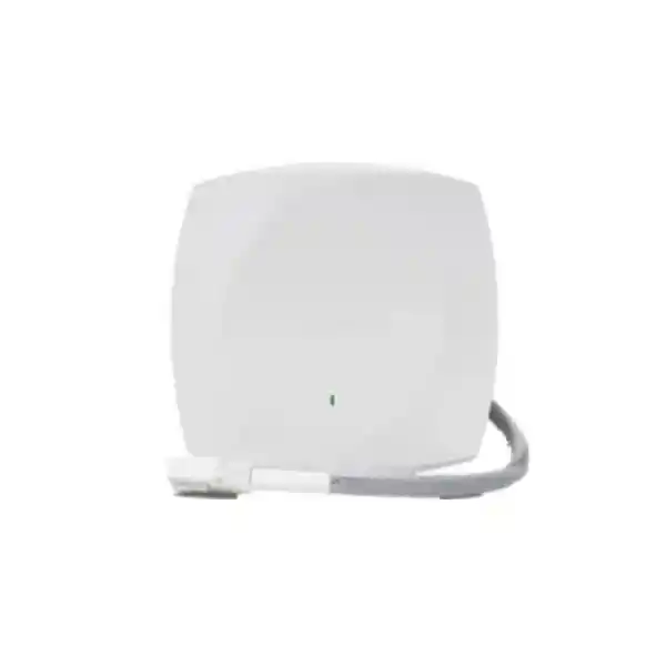
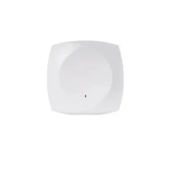
Cisco Wireless CW9174E Wi-Fi 7 Access Point
The Cisco Wireless CW9174E is designed for organizations that want the performance gains of Wi-Fi 7 without giving up control over antenna pattern, mounting position, coverage geometry or brownfield RF design. Its external-antenna architecture makes it especially useful where a standard ceiling-mounted omnidirectional access point cannot deliver the right signal shape, including warehouses, tall atriums, production areas, clinics, campuses, hospitality venues, corridors, retail spaces and offices with unusual construction.
For UAE deployments, the important question is not simply whether an access point supports Wi-Fi 7 on paper. The real design work includes choosing the correct radio mode, validating whether 6 GHz operation is permitted for the intended regulatory domain and software release, matching the antenna to the coverage objective, ensuring the switch can deliver the required PoE class, confirming multigigabit uplink capability, validating cabling quality and building a management and licensing plan that fits either Cisco Catalyst operations or Meraki cloud workflows.
Direct answer: who should choose the CW9174E?
Choose the Cisco CW9174E when your Wi-Fi 7 project requires deliberate antenna engineering rather than a fixed internal radiation pattern. The access point is the external-antenna member of the Cisco Wireless 9174 family. It supports a flexible radio architecture that can operate as a tri-band system using 2.4 GHz, 5 GHz and 6 GHz where the 6 GHz band is approved and supported, or as a dual-band 2.4 GHz and 5 GHz platform in locations or configurations where 6 GHz is unavailable. In tri-band operation, the design provides 2×2 service on 2.4 GHz and 4×4 service on both 5 GHz and 6 GHz. A dual-radio design can instead use 4×4 service on 2.4 GHz and 4×4 on 5 GHz.
This makes the CW9174E a particularly strong fit for network teams that need directional coverage, targeted aisle coverage, controlled spill between rooms, high-ceiling deployment, selective reuse of existing enterprise antenna infrastructure, or a carefully modeled radiation pattern. Cisco supports dedicated Wi-Fi 7 antenna options including the CW-ANT-T-O2-D8 omnidirectional ceiling antenna and the CW-ANT-T-D2-D8 directional patch antenna, together with adapter and mounting options for specific brownfield scenarios. The AP itself uses a single Octal DART, or DART-8, external antenna connector.
The platform also brings the infrastructure features expected from a modern enterprise access layer: a 100 Mbps/1 Gbps/2.5 Gbps/5 Gbps multigigabit RJ-45 uplink, dedicated IoT and scanning radios, BLE capability, WPA2/WPA3 security, 802.1X authentication support, USB connectivity, a local console interface, DC power capability and multiple PoE operating modes. Organizations buying the CW9174E should therefore size the entire access stack—switch port speed, PoE budget, controller or cloud subscription, licensing, antenna, mounting kit and structured cabling—rather than treating the AP as an isolated device.
CW9174E at a glance
Client-serving radios
Tri-band: 2.4 GHz 2×2 plus 5 GHz 4×4 plus 6 GHz 4×4, subject to local regulatory and software support. Dual-band: 2.4 GHz 4×4 plus 5 GHz 4×4.
Wired uplink
One RJ-45 multigigabit Ethernet interface supporting 100M, 1G, 2.5G and 5G link rates, allowing the wired edge to keep pace with high aggregate wireless throughput.
External antenna model
Single DART-8 external antenna connector with supported Cisco omnidirectional, directional and selected legacy antenna options for purpose-built RF patterns.
Enterprise operations
Supported with Cisco Catalyst wireless infrastructure and Meraki cloud management, giving customers a choice between controller-led and cloud-centric operating models.
Wi-Fi 7 architecture: what the new generation changes
Wi-Fi 7 is based on IEEE 802.11be and is built to improve throughput, spectrum efficiency, latency behavior and resilience under contention. The CW9174E supports the major Wi-Fi 7 mechanisms that matter to enterprise design, including 4096-QAM modulation, wider channel operation, Multi-Link Operation, preamble puncturing, uplink and downlink OFDMA and multiuser MIMO. These features should not be interpreted as an automatic guarantee of maximum throughput to every client. They are capabilities that become useful when the endpoint, channel plan, RF conditions, regulatory rules and upstream network are aligned.
4096-QAM increases the number of bits that can be encoded per symbol compared with earlier modulation levels, which can raise peak data rates when the client receives a very clean, strong signal. The practical engineering consequence is that the highest modulation schemes are usually achieved near the access point and under favorable signal-to-noise conditions. They do not remove the need for sensible cell sizing. A design that spaces APs too far apart may still provide basic connectivity but will reduce the amount of time clients can use the most efficient modulation and coding rates.
Preamble puncturing is important in wide-channel environments because it allows an AP to make use of usable portions of a broad channel even when part of that spectrum is affected by interference or another allocation. In earlier designs, a problem on one portion of a wide channel could force a narrower operating choice. Preamble puncturing provides more flexibility, although channel planning remains fundamental. The network still needs a clean RF design, sensible channel widths, appropriate transmit power and awareness of neighboring WLANs.
Multi-Link Operation is one of the most discussed Wi-Fi 7 capabilities. In compatible environments it allows a client and AP to coordinate traffic across multiple links rather than treating each band as an entirely separate connection. Benefits can include better effective throughput, lower latency or improved resiliency, depending on implementation and client support. Enterprises should validate the feature set of their target endpoints because a Wi-Fi 7 label on an AP does not mean every client supports every optional Wi-Fi 7 mechanism on day one.
The CW9174E supports channel widths up to 160 MHz on 5 GHz and up to 320 MHz on 6 GHz where permitted. Wide channels can increase peak throughput but consume more spectrum. In a high-density office or education deployment, multiple narrower channels can often create more total system capacity than a small number of very wide channels. In contrast, a controlled low-interference environment with fewer cells and demanding modern clients may benefit more from wider channels. The correct design balances per-client speed against channel reuse and collision domains.
External antenna engineering is the CW9174E’s defining advantage
The strongest reason to select the CW9174E instead of an internal-antenna model is control over RF geometry. Wireless design is not only a matter of transmit power. Antenna pattern determines where energy is concentrated, where nulls exist, how much signal reaches adjacent rooms, how much energy leaks into neighboring floors and how effectively a cell can be shaped around the users or devices it is intended to serve. In many enterprise spaces, a carefully chosen external antenna can improve usable signal quality while reducing unnecessary co-channel contention.
Cisco lists the CW-ANT-T-O2-D8 as a tri-band omnidirectional ceiling-mount antenna for the CW9174E. Published peak gain values are 2 dBi at 2.4 GHz, 5 dBi at 5 GHz, 5 dBi at 6 GHz and 2 dBi for the IoT function. An omnidirectional antenna is useful when the access point is positioned near the center of the intended service area and users are distributed around it. Typical examples include open offices, meeting clusters, education spaces and retail floors where a roughly radial horizontal coverage pattern is appropriate.
For more controlled coverage, Cisco lists the CW-ANT-T-D2-D8 directional antenna. Published peak gain values are approximately 6.6 dBi at 2.4 GHz, 5.7 dBi at 5 GHz, 5.7 dBi at 6 GHz and 6 dBi for IoT, with a directional pattern. A directional antenna can be a better choice for warehouses, long corridors, loading areas, selected production zones, high-ceiling spaces, lecture areas or situations where the designer wants to project energy toward clients while limiting energy behind the antenna. Directional RF design can also help reduce unwanted coverage beyond a tenant boundary or into adjacent cells.
The supported Wi-Fi 7 antenna family also includes a tri-band omnidirectional dipole option with RP-TNC connectivity when used with the appropriate cable or adapter arrangement. Cisco documents compatibility with selected earlier enterprise antennas as well. Brownfield compatibility can reduce installation disruption, but it should never be assumed solely because a connector can be adapted. Some legacy antennas are limited to 2.4 GHz and 5 GHz operation, and certain combinations can affect IoT functionality or require specific DART adapter cables. A proper migration plan therefore maps every existing antenna part number to the supported CW9174E accessory matrix.
Both RF performance and compliance depend on using a supported antenna combination. Antenna gain changes effective radiated power, so the regulatory domain, configured transmit power and antenna characteristics must be considered together. An antenna with higher gain does not create power; it concentrates RF energy. That can improve coverage in the intended direction but can also increase interference if the pattern is poorly aligned. For UAE projects, the antenna choice should be documented in the RF design and confirmed against the exact regulatory certification and software behavior of the supplied hardware.
FourTeck can support customers that need a wireless bill of materials to include not only the access point but also the correct antenna, DART or RP-TNC conversion accessory where applicable, mounting hardware, switch power budget, license and controller or cloud entitlement. For broader infrastructure planning, the FourTeck UAE main site provides a useful starting point for enterprise networking requirements and associated implementation services.
UAE 6 GHz planning: verify the regulatory state before promising tri-band service
The CW9174E hardware is capable of 6 GHz operation, but an external-antenna Wi-Fi 7 deployment must be designed around the rules of the country where the AP will operate. Cisco’s documentation explicitly notes that the 6 GHz radio is disabled in countries where use of the band is not allowed or where current software support is not available, with the possibility of later enablement after certification. Cisco also documents country-specific restrictions for external-antenna operation. Therefore, a UAE project should never be quoted on the assumption that every 6 GHz feature or 320 MHz channel mode is automatically available merely because the hardware contains a 6 GHz-capable radio.
A responsible procurement process checks the exact Cisco product regulatory domain, software train, controller or Meraki release, country configuration and any applicable local telecommunications rules at the time of deployment. This matters because frequency policy can evolve and because different access point models can have different allowed modes. If 6 GHz operation is not available for the target installation, the CW9174E can still operate as a strong dual-band Wi-Fi 7 platform using 2.4 GHz and 5 GHz, including a 4×4 configuration on both radios.
This regulatory distinction should also appear in tender language. Instead of specifying “6 GHz required” without qualification, a better scope asks for a Wi-Fi 7 external-antenna platform capable of the requested band subject to UAE approval, vendor certification and supported software. That prevents an implementation team from being forced into an unsupported radio mode and creates a cleaner path for future enablement if certification changes.
Spatial streams, radio flexibility and realistic throughput expectations
In tri-band configuration, the CW9174E uses two spatial streams on the 2.4 GHz serving radio and four spatial streams each on 5 GHz and 6 GHz. In dual-band configuration, 2.4 GHz and 5 GHz can both operate as 4×4 radios. Cisco describes aggregate PHY data rates of approximately 17.5 Gbps for the tri-band Wi-Fi 7 configuration under maximum channel-width assumptions and about 6.5 Gbps for the dual-band configuration. These are physical-layer aggregate rates, not a promise that an Ethernet application will transfer data at those exact numbers.
Wireless throughput is shared and half-duplex at the radio medium. Management frames, acknowledgments, contention, encryption overhead, protocol headers, retransmissions and airtime used by slower clients all reduce application throughput relative to PHY rate. Client devices may also have fewer spatial streams than the access point. Most business laptops and phones are commonly two-stream devices, so a 4×4 AP creates value through multiuser scheduling, receive diversity, beamforming opportunities and aggregate system capacity rather than giving one two-stream client four spatial streams.
This is why AP capacity planning should be based on airtime, client mix and application demand instead of headline data rate. A floor with 100 users mostly running messaging and SaaS tools has a different requirement from a design studio synchronizing large media files, a lecture hall with synchronized video, a warehouse with voice terminals and scanners, or a clinic with roaming workstations and latency-sensitive applications. Each scenario consumes the available airtime differently.
The CW9174E supports a large theoretical client association scale across its serving radios, but the supported association count should not be used as a design target. Good WLAN engineering aims to keep contention, retries, roaming behavior and channel utilization within acceptable limits. In high-density deployments, the number of active clients per radio is often more important than the number of clients that can merely remain associated.
Capacity sizing methodology for offices, campuses and public venues
A capacity-led design begins with expected concurrent devices rather than employee headcount alone. A modern user may carry a laptop, phone, tablet, wearable and guest device. Only some of those devices are active at the same time, but authentication, background synchronization and roaming still consume airtime. The network designer should estimate active clients per zone, expected throughput per active client, application criticality, peak concurrency and client radio capabilities. That information can then be translated into AP quantity and channel reuse objectives.
For general office productivity, the design should prioritize consistent 5 GHz service, controlled 2.4 GHz coverage for legacy and IoT endpoints, and 6 GHz capacity where legally supported and operationally useful. Wide 160 MHz or 320 MHz channels may look attractive in a throughput test, but they reduce the number of non-overlapping channels available for reuse. In a multi-floor office, a narrower channel plan may deliver greater aggregate capacity because neighboring cells can operate on different frequencies with less contention.
Lecture halls, auditoriums and conference rooms need more deliberate modeling. A room can contain a dense group of endpoints in a small physical area, so coverage is rarely the limiting factor. Airtime and contention are the limiting resources. Designers may use lower transmit power, carefully placed directional antennas, smaller cells and more available channels to distribute users. The external antenna option makes the CW9174E useful for this type of cell shaping, but each antenna should be modeled and validated on site.
Warehouses require a different method. Racks, inventory, forklifts and moving stock change RF propagation. A signal that looks strong in an empty building can behave very differently after racks are filled. The design should consider aisle direction, mounting height, antenna down-tilt, material absorption, forklift movement and the client antenna characteristics of scanners or vehicle-mounted terminals. Directional antennas can provide long, controlled cells, but overly long cells may cause sticky-client behavior or poor roaming if transmit power is excessive.
For any environment with voice over Wi-Fi, collaboration, real-time control or mobile clinical workflows, the success metric should include roaming, latency, packet loss and retry rate—not just signal strength. A Wi-Fi 7 AP cannot compensate for a poor roaming domain, overloaded RADIUS server, incorrect QoS policy or inadequate wired uplink. End-to-end design is essential.
RF survey and predictive design for the CW9174E
A predictive survey should begin with accurate floor plans, ceiling height, wall materials, rack geometry and intended AP mounting positions. The RF model should use the actual antenna pattern planned for the CW9174E, not a generic omnidirectional placeholder. For a directional antenna, orientation is as important as placement because rotating or tilting the antenna changes the service zone. Cisco’s dedicated antenna options include orientation sensing features that can help with post-deployment verification, but the survey design still needs to define the expected azimuth and tilt.
The designer should model coverage thresholds appropriate to the applications. General data may tolerate a lower received signal strength than real-time voice, location-sensitive services or applications that need consistently high modulation rates. Signal-to-noise ratio should be evaluated along with RSSI because a strong signal in a noisy environment can still perform poorly. Channel utilization and interference sources need measurement after the WLAN is installed and populated.
An active validation survey is especially valuable for external-antenna projects. It confirms that the installed antenna is facing the intended direction, that mounting height matches the model, that cabling and connectors are correct, and that attenuation from real furniture, racks, glass, machinery or partitions matches the prediction. The survey should also confirm roaming paths. A client walking from one zone to another should see a controlled transition between cells rather than staying connected to a distant AP because the old cell was designed too large.
For brownfield upgrades, pre-deployment measurements can identify where the existing WLAN is constrained. High retries may indicate interference rather than weak signal. Excessively strong overlap can create co-channel contention. Poor roaming may be caused by uneven cell edges. Replacing old APs one-for-one without understanding these conditions can preserve the old design’s weaknesses even when the new radio is much faster.
FourTeck’s UAE IT services practice can be incorporated into a broader deployment scope where customers require survey planning, installation coordination, switching changes, VLAN integration, authentication or post-deployment validation rather than hardware supply alone.
5 Gb multigigabit Ethernet: design the wired edge for Wi-Fi 7
The CW9174E provides one RJ-45 Ethernet uplink that can negotiate at 100 Mbps, 1 Gbps, 2.5 Gbps or 5 Gbps. This is significant because the wireless side can generate aggregate traffic well above one gigabit. A legacy 1 Gb switch port may become a bottleneck long before the AP reaches its radio capacity. A 2.5 Gb or 5 Gb multigigabit access port gives the AP more room to aggregate traffic from modern clients, especially in high-density or large-file environments.
The switch should be selected not only for port speed but also for total switching capacity, uplink bandwidth, PoE budget and policy features. A closet containing 24 or 48 Wi-Fi 7 APs can create substantial aggregate traffic. The access switch therefore needs adequate uplinks toward distribution or core, typically with redundancy and enough oversubscription headroom for the application profile. Simply connecting each AP at 5 Gb does not help if the switch has an undersized uplink that becomes congested during peak periods.
Cabling is equally important. Cisco specifies Cat 5e, Cat 6 or Cat 6A for multigigabit operation. In a new enterprise build, Cat 6A is often preferred where the project wants stronger margin for multigigabit and future edge requirements, but the correct choice depends on distance, bundle size, pathway design, interference environment and local standards. In an existing building, cable certification can determine whether older runs can reliably sustain 2.5 Gb or 5 Gb links.
The deployment team should record negotiated link speed after installation. A CW9174E connected to a nominal 5 Gb switch port may fall back to 2.5 Gb or 1 Gb if cabling quality is inadequate. Monitoring the actual Ethernet rate, errors and retransmissions prevents an invisible wired problem from being misdiagnosed as a wireless problem.
PoE behavior: the switch power budget directly affects radio capability
The CW9174E can operate with several power sources, and those modes are not equivalent. With 802.3bt Class 5 UPOE or the supported 54 V DC power source, the AP can run the full tri-band 2×2/4×4/4×4 radio configuration with a 5 Gb Ethernet link and USB output up to 9 W. Cisco specifies a maximum powered-device requirement of 37 W for this configuration. In dual-band 4×4/4×4 mode with the same higher-power source, the maximum requirement is lower and the 5 Gb link plus USB capability remain available.
With 802.3at PoE+, Cisco documents operation with tri-band service but limits the Ethernet link to 2.5 Gb and reduces available USB power to 2.5 W. This mode has a maximum powered-device requirement of 25.5 W. In the lowest 802.3af PoE mode, the platform is heavily constrained, with a reduced radio configuration, a 1 Gb link and no USB power. Therefore, a design that purchases Wi-Fi 7 APs but reuses a low-power legacy PoE access layer may not deliver the intended radio and wired performance.
This power behavior should be modeled at switch level. The designer needs to calculate the maximum simultaneous power draw across all AP ports, reserve headroom for other PoE devices and account for power-supply redundancy mode. A switch with a sufficient per-port standard can still fail the overall design if its chassis power budget cannot deliver the required wattage to every AP at peak.
Cisco publishes typical 802.3at power consumption for the CW9174E around 17.6 W under its stated test assumptions, with idle consumption around 12.6 W. Those typical figures are useful for operational energy estimates, but switch sizing should use the supported maximum requirement for the selected mode rather than the average. Real consumption changes with radio activity, USB use, link speed, ambient conditions and enabled features.
For a new project, the cleanest bill of materials pairs the CW9174E with an access switch that supports both multigigabit Ethernet and sufficient 802.3bt power on the required number of ports. For a phased upgrade, PoE+ may be a practical interim step if its limitations are explicitly accepted and documented.
Enterprise security: WPA3, 802.1X and identity-aware access
The CW9174E supports modern enterprise WLAN security, including WPA2, WPA3, Enhanced Open and strong AES-based cipher suites. For corporate access, the preferred architecture is generally WPA3-Enterprise or a supported enterprise authentication design integrated with a RADIUS-based identity platform. Cisco supports multiple EAP methods including certificate-based EAP-TLS and tunneled methods. The right method depends on endpoint management, certificate infrastructure, user directory design and security policy.
EAP-TLS is often selected for managed enterprise devices because authentication is based on certificates rather than reusable user passwords. A mature deployment automates certificate issuance, renewal and revocation through device-management tooling. This can reduce credential phishing risk and gives administrators a strong identity signal for network policy. Guest, BYOD and IoT devices may need different onboarding workflows, and those workflows should be intentionally separated from the corporate managed-device SSID.
When Cisco Identity Services Engine is part of the architecture, the wireless network can apply identity-aware authorization policies and dynamic segmentation decisions. The WLAN can distinguish employee devices, contractors, guests and IoT classes and assign access according to policy. This is more scalable than creating a separate static SSID for every organizational group. VLANs, downloadable ACLs, security group policies or other supported enforcement mechanisms can be selected according to the broader Cisco design.
Wireless encryption is only one layer. The AP’s management plane should also be protected through role-based administration, secure controller or dashboard access, multi-factor authentication where available, change logging and least-privilege operations. Switch ports should be secured, unused services disabled and management networks restricted. Firmware and controller releases should follow a change-management process that includes security advisories, compatibility checks and rollback plans.
The WLAN must also align with upstream firewall and segmentation policy. If the project includes secure internet breakout, guest isolation, inter-VLAN controls, application inspection or remote-site connectivity, the wireless design should be coordinated with the security edge. FourTeck’s Firewall Dubai practice can support customers that want the access layer and security policy designed as one end-to-end solution.
Catalyst controller operations or Meraki cloud management
One of the strategic benefits of the Cisco Wireless 9174 family is support for different operating models. The CW9174E can be deployed in Cisco Catalyst wireless environments using supported Catalyst 9800 Series Wireless Controllers, or it can participate in the Meraki cloud-managed stack with the appropriate software and subscription. This gives organizations more flexibility when standardizing hardware across sites with different operational requirements.
A Catalyst 9800 design is well suited to enterprises that want controller-centric WLAN operations, established Cisco campus integration, deep policy control and integration with Catalyst Center. Cisco lists support for multiple physical and virtual Catalyst 9800 controller platforms. The correct controller is selected according to AP scale, client scale, throughput, high-availability requirements, site topology and feature requirements. The CW9174E does not provide embedded wireless controller functionality on the AP itself, so a Catalyst deployment needs a supported controller architecture rather than assuming one AP will become the controller for the others.
Catalyst Center can add automation, analytics, assurance workflows and networkwide operational context. A large campus can use centralized provisioning, policy, software management and telemetry to reduce manual configuration. Integration with Cisco Spaces can support location and experience use cases, while ISE can provide identity and access-control integration. These tools are most valuable when the network operations team has clear processes for incidents, changes, baselines and escalation.
Meraki cloud management offers a different operational experience. It is attractive for distributed organizations that want centralized cloud visibility, standardized templates, remote troubleshooting and simplified site administration without maintaining an on-premises WLAN controller at every location. Retail chains, branch networks, education groups and multi-site businesses can benefit from the common dashboard model, particularly when network staff need to operate many remote sites with a small central team.
The choice between Catalyst and Meraki should be made before procurement because subscriptions, migration workflow, feature expectations and operational responsibilities differ. The hardware’s management flexibility should not be interpreted as a reason to postpone architecture decisions. A clear target operating model makes the deployment cleaner, helps the customer purchase the correct subscription and avoids rework during staging.
Cisco states that Wi-Fi 7 access points including the 9174 Series require a Cisco Networking Subscription, with Wireless Essentials or Wireless Advantage licensing choices. License selection should be based on the features and support level required by the customer. The quotation should therefore identify the intended management platform, subscription tier and term rather than listing only the AP hardware.
Assurance, scanning radio and troubleshooting visibility
The CW9174E includes a dedicated tri-band scanning radio. A separate scanning function is valuable because it can observe the RF environment without requiring the client-serving radio to spend as much time away from its primary channel. Depending on the management architecture and enabled features, this can improve visibility into interference, rogue activity, channel conditions and client experience.
Cisco Intelligent Capture and associated assurance capabilities are designed to provide deeper diagnostic insight into issues such as latency, interference and client connectivity. In a mature operations environment, telemetry reduces dependence on manual packet captures and “walk to the user’s desk” troubleshooting. It can help the help desk determine whether an incident is caused by RF, authentication, DHCP, DNS, roaming, upstream routing or endpoint behavior.
The greatest operational value comes from baselining. Teams should record normal channel utilization, client counts, retry rates, signal quality, authentication time and application performance before a problem occurs. When an incident begins, current values can be compared with that baseline. Without a baseline, a high utilization percentage may appear alarming even though it is normal for a particular venue during business hours.
A Wi-Fi 7 refresh is therefore a good opportunity to upgrade the operational model as well as the radio hardware. Dashboards, alert thresholds, log retention, RADIUS monitoring, switch telemetry and incident playbooks should all be reviewed during migration.
BLE, IoT radio and application hosting
The CW9174E incorporates a dedicated IoT radio and Bluetooth Low Energy capability. Cisco documents integrated BLE 5.3 with a path to BLE 6 through future software support. BLE can be used for location-related workflows such as asset tracking, wayfinding and analytics when combined with the appropriate application platform and tags or devices. The AP therefore becomes more than a pure Wi-Fi endpoint; it can participate in a broader building or operational technology strategy.
IoT design should still separate the physical radio capability from application requirements. Asset tracking, environmental sensors, industrial telemetry and occupancy use cases can differ in protocol, location accuracy, security model and backend integration. The network team should document which protocols are required, which AP antenna options support those functions and what software or cloud services are needed to convert radio observations into business data.
The AP also supports USB connectivity and Cisco application-hosting capabilities. Containerized applications and supported hardware modules can bring selected processing closer to the edge, reducing the need for a separate overlay appliance in certain IoT scenarios. USB power availability depends on the AP’s PoE mode, which is another reason to design switching power and application requirements together.
Where IoT traffic is business-critical, segmentation and lifecycle management become essential. IoT devices often have long replacement cycles and limited local security controls. A secure architecture restricts which services they can reach, monitors unusual behavior and maintains an inventory of device identity, firmware and ownership.
Deployment profiles in the UAE
Corporate offices
Use the CW9174E where meeting spaces, partitions, atriums or tenant boundaries benefit from deliberate cell shaping. In open office areas a tri-band omnidirectional antenna may be appropriate, while directional antennas can help isolate conference zones or project coverage into difficult areas. The design should emphasize 5 GHz capacity, smooth roaming, secure enterprise authentication and multigigabit switching.
Warehouses and logistics
Directional external antennas make the CW9174E attractive for aisles, loading areas and selective zones. Survey work should account for rack height, stock type, moving forklifts and scanner behavior. Mounting, antenna alignment and cell-edge validation are critical because excessive coverage can be as harmful to roaming as insufficient coverage.
Healthcare
Hospitals and clinics require reliable roaming, security and change discipline. The AP can support modern client density while external antennas help address corridors, treatment areas and specialized room geometry. Clinical applications should be tested for roaming thresholds, latency and authentication behavior before cutover.
Education
Classrooms, lecture halls and common areas have highly variable density. The CW9174E’s RF flexibility can help shape cells around teaching spaces. Capacity planning should avoid overuse of very wide channels in dense buildings and should consider large bursts of simultaneous authentication at the beginning of sessions.
Hospitality
Hotels, conference centers and premium venues need predictable guest experience across rooms, corridors and public areas. Directional coverage can reduce spill through complex construction, while centralized management helps operations teams maintain consistent SSIDs, guest policies and visibility across multiple properties.
Retail and public venues
Retail stores and event spaces combine guest traffic, payment systems, staff handhelds and IoT. The design should prioritize segmentation, capacity and operational monitoring. External antennas can target coverage to sales floors while limiting unnecessary propagation into neighboring tenants or exterior areas.
High-ceiling warehouses, cold rooms and directional coverage
High-ceiling spaces are among the environments where an external-antenna AP can provide the biggest design advantage. Mounting an internal omnidirectional AP 10 or 15 meters above the floor can create a large cell with significant energy in unintended directions, while clients at floor level may have relatively weak transmit power back to the AP. A directional antenna allows the designer to concentrate the coverage toward the work area and control the cell boundary more precisely.
The link budget must be considered in both directions. AP transmit power can be much higher than the transmit power of a handheld scanner or phone, so a client may hear the AP while the AP struggles to hear the client. Antenna gain can help, but the design should still target realistic client performance. Mounting height should be selected based on aisle geometry, obstruction and antenna beam rather than building convenience alone.
Cold storage creates additional considerations. Condensation, insulation panels, door openings and metallic structures can change propagation. The CW9174E has a published operating temperature range down to -20°C, which can be useful in cooler environments, but the complete installation must be evaluated for temperature, humidity, condensation and cable performance. The product is an indoor enterprise access point, so environmental suitability should be confirmed for the exact location rather than inferred from temperature alone.
For warehouses, a pilot aisle is often a smart deployment method. The team installs the planned AP, antenna and mount at the real height, loads the aisle with representative stock and tests scanners while walking and driving normal routes. This validates coverage, roaming and mounting before the pattern is repeated across dozens of aisles.
Voice, video and collaboration over Wi-Fi 7
Real-time applications benefit from the lower latency potential and improved efficiency of newer Wi-Fi generations, but the network still needs consistent QoS from endpoint to application. Wireless access categories, DSCP marking, switch trust boundaries, WAN policy and application behavior should align. A voice packet that receives priority on the WLAN but is treated as best effort at the switch or firewall can still experience jitter and loss.
Roaming is equally important. A video call or voice session can expose delays that users may not notice while browsing. The RF design should create predictable cell overlap, and the security design should support fast enough reauthentication for the client population. Client drivers and operating systems make their own roaming decisions, so validation must include the actual devices used by staff rather than only a survey laptop.
Channel width should be selected with real-time performance in mind. Wider channels increase peak throughput but can be more exposed to interference and reduce channel reuse. In a dense office, clean 40 MHz or 80 MHz cells may deliver more consistent collaborative performance than an aggressive 160 MHz plan. Where 6 GHz is supported, the additional spectrum can provide more room for modern clients, but coverage characteristics and device support still need validation.
Application testing should include peak-hour conditions. A WLAN that performs well at midnight can behave differently when hundreds of users arrive, background updates begin and meeting rooms fill. Staging, pilot deployment and post-cutover monitoring are therefore essential parts of a Wi-Fi 7 rollout.
Migration from Wi-Fi 5, Wi-Fi 6 or older Cisco access points
A successful migration starts by separating the physical replacement plan from the RF redesign. Existing mounting brackets may be reusable in many Cisco enterprise deployments, and the CW9174 family retains compatibility with common Cisco bracket formats. This can reduce labor and downtime. However, simply installing the new AP on the old bracket can leave the network with a channel plan, AP density and power settings that were created for a much older radio generation.
The first audit should inventory AP models, controller versions, switch models, PoE class, Ethernet speeds, cable category, antenna part numbers, mounting hardware and license state. If external antennas are already deployed, each antenna must be checked against the CW9174E support matrix. Some legacy antennas can be reused only for 2.4 GHz and 5 GHz, while others require DART adapter cables. A migration BOM should therefore identify every accessory, not just the AP quantity.
The switching audit often reveals the largest hidden cost. Older access switches may provide only 1 Gb Ethernet and 802.3af power. The CW9174E can operate in reduced modes under lower power, but that would underuse the new hardware. Projects should decide whether to replace the access layer at the same time, deploy Wi-Fi 7 in phases, or temporarily accept 2.5 Gb/PoE+ constraints until switching is upgraded.
Controller and software compatibility must also be checked. Cisco lists minimum supported IOS XE and Meraki software versions for the 9174 family. An existing controller may require a code upgrade before the first AP can join. In a production campus, that code change should be tested for compatibility with all other AP models and network features. Mixed-generation deployments are common, but their software matrix must be validated.
SSID migration is an opportunity to simplify. Old WLANs often accumulate temporary SSIDs, outdated encryption, overlapping guest networks and special-purpose VLANs. Each extra SSID consumes beacon airtime and operational attention. A refresh can consolidate SSIDs, move managed devices toward stronger certificate-based authentication and segment users dynamically where supported.
For data-center and compute dependencies that need to be upgraded alongside the wireless environment, customers can also review FourTeck Server Dubai for infrastructure options that support authentication, management, applications and other enterprise workloads connected to the WLAN.
Physical interfaces, dimensions and environmental profile
The CW9174E measures approximately 8.9 x 8.9 x 1.95 inches, or 22.6 x 22.6 x 4.9 centimeters, without mounting brackets, and weighs approximately 3.26 pounds or 1.47 kilograms. Its primary wired interface is the 100M/1G/2.5G/5G RJ-45 multigigabit Ethernet port. It also includes an RJ-45 management console interface, USB 2.0, and a 54 V DC power input for the supported external power adapter.
The AP’s published operating temperature range is -20°C to 50°C, with 10% to 90% noncondensing operating humidity. Storage temperature is broader. These figures help determine basic environmental suitability, but the installer must still consider real conditions above ceilings, near roofs, inside cabinets or close to industrial equipment. UAE buildings can have high ambient temperatures in service spaces if air conditioning is interrupted, so AP locations should not be treated as equivalent to occupied-room temperatures without verification.
Status indication is provided by the AP LED, supporting boot, association and operating-state diagnostics. Physical access to the console and power connections should be considered during installation. In secure environments, APs should be positioned and mounted so they cannot be casually removed or disconnected, while still allowing authorized maintenance.
The CW9174E is an indoor access point. If a project requires outdoor exposure, direct moisture, dust-heavy industrial conditions or other harsh environments, the customer should select an access point specifically certified for those conditions rather than relying on indoor environmental limits.
Mounting and installation planning
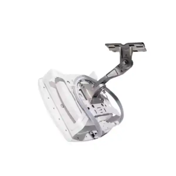
Cisco supports common enterprise mounting brackets with the CW9174 family, including low-profile and universal bracket options and T-rail accessories for suspended ceilings. This continuity can make brownfield deployment faster because many sites already have compatible Cisco mounting infrastructure. External antennas, however, require their own mounting and alignment plan. The directional CW-ANT-T-D2-D8 can be used with an articulating mount, and Cisco offers an integrated AP-and-antenna mounting option for specific designs.
The installer should receive a marked-up floor plan showing AP ID, switch port, cable ID, mounting height, antenna part number, orientation, tilt, and any special adapter. This is especially important when dozens of external antennas look similar. A post-installation photograph can document the final orientation and make later troubleshooting easier. If the antenna supports orientation sensing, that telemetry can be compared with the intended design.
Cable service loops and connector strain should be managed so that the AP and antenna are not left under mechanical tension. Access points mounted above suspended ceilings need adequate clearance and should not be buried behind metal ductwork that changes the RF design. Fire and building codes may also dictate cable type, support methods and placement.
After physical installation, commissioning should verify AP join status, software version, country configuration, antenna settings, radio state, PoE mode, negotiated Ethernet speed, VLAN reachability, DHCP, DNS, NTP, RADIUS and management telemetry before the area is opened to users.
Designing for roaming instead of maximum cell size
One common wireless mistake is to maximize coverage from every AP. Stronger is not always better. If a client can still hear an AP far down a corridor, it may stay connected longer than desired even when a closer AP is available. The result can be low data rates, retransmissions and poor voice quality. The goal is predictable overlap at roaming boundaries, not the largest possible footprint.
External directional antennas make cell shaping easier because energy can be concentrated into the intended zone. In a warehouse aisle, for example, the designer can create a long narrow service area, but the cell should still end at a point that encourages the scanner to roam before its uplink becomes weak. In office areas, transmit power should typically be balanced against common client power so that the uplink and downlink have similar usable range.
Roaming tests should include walking and mobile equipment at realistic speeds. The team should observe roam times, selected bands, RSSI before handoff, authentication delay and packet loss. It is not enough to confirm that a device eventually associates with the next AP. Voice and real-time workflows need the transition to occur quickly enough to avoid user impact.
Client diversity matters. Different phones, laptops, scanners and specialized devices can make different roaming decisions. A WLAN intended to support a known fleet should be validated with that fleet, especially where device firmware is controlled by the organization.
SSID, VLAN and segmentation strategy
A modern Wi-Fi 7 project should minimize unnecessary SSIDs. Every broadcast WLAN sends management traffic, and excessive SSIDs consume airtime across every channel. Instead of creating one SSID per department, organizations can often use a smaller number of WLANs and apply identity-based policy after authentication. Corporate managed devices, guest users and specialized IoT classes may still require separate onboarding models, but the number should be driven by technical need.
VLAN design should be scalable. Very large Layer 2 domains can create operational and failure-domain concerns, while excessively small VLANs can add complexity. The right model depends on campus architecture, mobility requirements, controller mode and segmentation approach. Where identity systems are available, policy can follow the user or device rather than being tied entirely to a static VLAN.
Guest WLANs should be isolated from corporate resources and should have explicit internet access, DNS and captive-portal policy. IoT networks should restrict east-west communication where unnecessary and allow only required application destinations. Management traffic should be separated and protected from user networks. These controls need consistent enforcement across wireless, switching and firewall layers.
The CW9174E supports the secure wireless foundation, but segmentation outcomes depend on the end-to-end Cisco and security architecture. A proper low-level design documents SSID names, authentication, encryption, VLAN or policy mapping, DHCP scopes, DNS behavior, ACLs, firewall rules, QoS and logging.
Operational lifecycle: staging, rollout, monitoring and upgrades
Enterprise wireless deployments should be staged before field installation. Staging confirms that APs are recognized by the target controller or cloud organization, receive the intended software, use the correct regulatory configuration and can authenticate to the management platform. Templates, tags, site assignments and RF profiles can be prepared in advance so field technicians spend less time configuring devices individually.
Rollout should be phased where business continuity matters. A pilot floor or building allows the team to validate the design with production clients before repeating it across the estate. Success criteria should include association rate, authentication time, roaming, retry rate, channel utilization, user complaints, Ethernet negotiation and switch power draw. A defined rollback plan is essential if controller software or authentication changes are included.
After deployment, monitoring should focus on trends rather than only outages. Rising channel utilization may show that client density has increased. Higher retry rates can reveal new interference. Changes in client capability can support a shift toward 6 GHz or different channel widths when regulatory and endpoint conditions permit. Monitoring PoE consumption and switch port errors can expose infrastructure issues before they become widespread user incidents.
Software maintenance should follow a regular cycle. Wireless releases include security fixes, client interoperability improvements, regulatory changes and feature updates. However, the newest release is not always the correct production release for every customer. Enterprises should follow Cisco’s recommended software guidance, validate controller and AP compatibility, test representative clients and schedule upgrades with change control.
Configuration backups, administrator access controls, license renewal dates and hardware support should be tracked as part of the same lifecycle. The wireless network is a production system and should be operated with the same discipline as switching, firewall and server infrastructure.
UAE procurement considerations for the Cisco CW9174E
A complete quotation should identify the exact CW9174E part number and regulatory domain, selected antenna, required antenna cable or adapter, AP mounting bracket, antenna mount, power method, Cisco Networking Subscription, controller or cloud management requirement and support coverage. Separating these items in the BOM makes it easier to confirm that the installation can actually be completed when the hardware arrives.
Customers should also provide the number of APs, site locations, preferred management model, current switch model, current controller model, existing antenna inventory, ceiling height and target applications. That information allows the supplier to identify compatibility gaps early. A quote based only on “CW9174E quantity 50” cannot reveal whether the customer also needs 50 directional antennas, adapter cables, 802.3bt switch upgrades or additional controller capacity.
For UAE multi-site organizations, logistics planning should include staging location, labeling convention, delivery sequencing and spare strategy. Large projects may benefit from pre-staged APs grouped by site so installers can mount devices without sorting dozens of identical cartons on location. A small percentage of spare APs and antennas can reduce downtime if a unit is damaged during installation or fails later.
Warranty and support requirements should match the business impact of wireless downtime. A warehouse relying on Wi-Fi scanners may need a faster replacement and escalation path than a small guest-only office. The project owner should define response objectives and confirm the selected Cisco support coverage accordingly.
Organizations with requirements outside the UAE can coordinate regional sourcing through FourTeck’s global site, while UAE deployments can be scoped through the local team with antenna, switching, security and implementation requirements captured in one request.
Common design mistakes to avoid
Mistake 1: choosing the CW9174E without choosing an antenna. The external antenna is part of the RF system, not an optional cosmetic accessory. The intended coverage pattern, band support, mounting method and regulatory limits must be known before the BOM is complete.
Mistake 2: assuming 6 GHz operation is universal. 6 GHz availability depends on country regulation, certification, software and external-antenna rules. The design should validate the UAE regulatory state for the exact deployment rather than copying a US configuration.
Mistake 3: reusing 1 Gb and low-power switch ports without assessing impact. The AP can fall back to reduced link speed and constrained radio capability under lower PoE. That may be acceptable in a phased migration, but it should be a documented decision.
Mistake 4: enabling the widest possible channel everywhere. 160 MHz and 320 MHz channels can improve peak rates, but they consume spectrum. Dense sites often need narrower channels for better reuse and total capacity.
Mistake 5: installing one AP per old AP location without a survey. A new radio generation and external antenna can justify different placement, power and channel plans. One-for-one replacement preserves physical convenience, not necessarily good RF design.
Mistake 6: treating associated-client limits as a sizing target. Capacity is governed by active airtime demand, application behavior and RF contention. The design should target user experience, not the maximum number of devices that can remain connected.
Why the CW9174E can be a better fit than an internal-antenna AP
An internal-antenna access point is usually simpler to install and is ideal for many standard office ceilings. The CW9174E becomes preferable when the standard pattern does not match the space. Directional antennas can project RF along aisles, into a lecture area or across an open zone while reducing energy elsewhere. External omnidirectional antennas can place the radiating element separately from the AP body when mounting constraints require it.
External antennas also provide a migration path in buildings that already have designed antenna systems, although compatibility must be verified. In some industries, moving only the AP electronics while retaining a validated antenna position can reduce physical disruption. In other cases, a Wi-Fi 7 upgrade is the right time to replace antennas as well so the system can support all intended bands and IoT functions.
The tradeoff is engineering complexity. An external-antenna system has more parts, more mounting decisions and more opportunity for incorrect orientation or adapters. This is why the CW9174E should be treated as a design-led product. When the project has a qualified RF plan, the flexibility is a major advantage. When the project has a simple standard ceiling and no special coverage constraints, an internal-antenna model may be easier to deploy.
FourTeck can help customers compare these deployment models before purchase, avoiding the cost of choosing external antennas where they add no value or internal antennas where they cannot achieve the needed RF pattern.
Technical specification summary
| Category | CW9174E specification / design note |
|---|---|
| Wireless generation | Wi-Fi 7 / IEEE 802.11be with backward support for earlier enterprise Wi-Fi generations. |
| Tri-band radio mode | 2.4 GHz 2×2, 5 GHz 4×4, 6 GHz 4×4 where 6 GHz is approved and supported. |
| Dual-band radio mode | 2.4 GHz 4×4 plus 5 GHz 4×4. |
| Wi-Fi 7 functions | 4096-QAM, Multi-Link Operation, preamble puncturing, OFDMA, MU-MIMO and wide-channel support including up to 320 MHz on 6 GHz where permitted. |
| Ethernet | One 100M/1G/2.5G/5G multigigabit RJ-45 uplink. |
| External antenna | Single DART-8 connector; supported Cisco Wi-Fi 7 omnidirectional and directional antennas plus selected legacy options with appropriate accessories. |
| PoE | Full-performance profiles available with 802.3bt Class 5; operation also supported at reduced capabilities with 802.3at and 802.3af. |
| USB | USB 2.0, with available output power dependent on PoE mode. |
| IoT and scanning | Dedicated IoT radio and dedicated tri-band scanning radio; integrated BLE capability. |
| Security | WPA2, WPA3, Enhanced Open, 802.1X and supported enterprise EAP methods with modern AES-based encryption. |
| Management | Supported in Cisco Catalyst controller environments and Meraki cloud-managed deployments with appropriate software and subscription. |
| Dimensions | Approximately 22.6 x 22.6 x 4.9 cm without mounting brackets. |
| Weight | Approximately 1.47 kg. |
| Operating temperature | Approximately -20°C to 50°C, subject to installation and environmental requirements. |
Frequently asked technical questions
Does the CW9174E always use 6 GHz?
No. The hardware supports 6 GHz, but operation depends on country regulation, certification and software. In environments where 6 GHz is unavailable, the AP can operate in dual-band 2.4 GHz and 5 GHz mode.
Is a 5 Gb switch port mandatory?
Not for basic operation, but a 5 Gb multigigabit port is required to obtain the highest documented wired-link mode. Lower PoE profiles can also restrict the negotiated Ethernet speed.
Can existing Cisco antennas be reused?
Selected legacy antennas are supported with restrictions and, in some cases, adapters. Some legacy antennas are limited to 2.4 GHz and 5 GHz or affect IoT capabilities, so part-number validation is required.
Does the AP include an embedded controller?
No. Cisco documents that embedded wireless controller functionality is not supported on the CW9174 family. Catalyst deployments use supported Catalyst 9800 controller architecture, while Meraki deployments use cloud management.
Is 802.3at PoE+ enough?
It can power the AP in supported modes, but Cisco documents limitations compared with 802.3bt Class 5, including reduced Ethernet link speed and lower USB power. Full design intent should be checked before deciding PoE+ is sufficient.
Which antenna is best?
There is no universal answer. Omnidirectional antennas suit centrally located cells, while directional antennas are valuable for aisles, corridors and targeted zones. The correct choice depends on a predictive or measured RF design.
Decision recap: when the CW9174E is the right investment
The Cisco Wireless CW9174E is the right choice when your organization needs an enterprise Wi-Fi 7 platform with external antenna flexibility and a strong wired access architecture. It is especially compelling where RF pattern control, brownfield antenna migration, high ceilings, targeted coverage or unusual physical layouts make a standard internal-antenna AP less suitable. Its 5 Gb multigigabit uplink, flexible radio modes, WPA3 security, IoT and scanning radios, Cisco management choices and multiple PoE profiles make it a modern platform for campus and distributed enterprise networks.
The product should not be purchased as a standalone line item without design context. The best result comes from a BOM that includes the correct antenna and mounting kit, adequate 802.3bt PoE, multigigabit switch ports, certified cabling, controller or cloud capacity, subscription licensing, RF survey and security integration. UAE 6 GHz operation should be explicitly validated for the exact regulatory domain and software state of the project.
For organizations upgrading from earlier Cisco wireless generations, the CW9174E can support a structured migration that reuses selected mounting or antenna assets where appropriate while modernizing the radio, switching, policy and assurance layers. The result should be measured in better user experience, predictable roaming, stronger security and easier operations—not merely a higher headline data rate.
Quotation input checklist for FourTeck UAE
To receive an accurate CW9174E quotation and deployment recommendation, provide the information below. Supplying these details lets the engineering team identify antenna, power, switching, licensing and controller requirements before the commercial BOM is finalized.
Number of APs, number of locations, city/emirate, floor count and whether deployment is new or a refresh.
Office, warehouse, school, hospital, hotel, retail, venue or mixed environment, with ceiling heights and floor plans if available.
Omnidirectional, directional, unknown, or existing Cisco antenna part numbers that need compatibility checking.
Switch make/model, available PoE standard, PoE budget, port speed and cabling category.
Catalyst 9800 controller, Meraki cloud, new deployment, or existing architecture requiring compatibility validation.
ISE, RADIUS, Active Directory, certificate authentication, guest access, BYOD and segmentation requirements.
Voice, video, scanning, clinical applications, POS, IoT, high-throughput design workloads or standard office traffic.
Supply only, staging, RF survey, installation, controller configuration, switching integration, testing or managed support.
FourTeck consultation panel
For a production-ready Cisco CW9174E design in the UAE, FourTeck can help turn the access point specification into a complete deployable solution. The engagement can cover AP and antenna selection, regulatory-domain validation, Wi-Fi 7 radio planning, predictive and validation surveys, multigigabit switch sizing, PoE budget calculation, structured cabling checks, controller or Meraki architecture, Cisco subscription selection, security integration, deployment staging and acceptance testing.
A focused technical consultation is most valuable when the customer shares the real environment rather than only the desired model number. Floor plans, ceiling heights, rack layouts, expected device counts, application types, current switch models and existing Cisco infrastructure allow the design to be sized around user experience and operational goals. The resulting quotation can then distinguish mandatory components from optional enhancements and avoid hidden dependencies during installation.
The CW9174E is a powerful Wi-Fi 7 platform, but its greatest value comes from correct RF geometry, adequate PoE, multigigabit backhaul and disciplined enterprise operations. FourTeck UAE can structure those layers as one solution so the network is ready not just for a specification sheet, but for real users, real roaming and real production traffic.

Reviews
There are no reviews yet.