
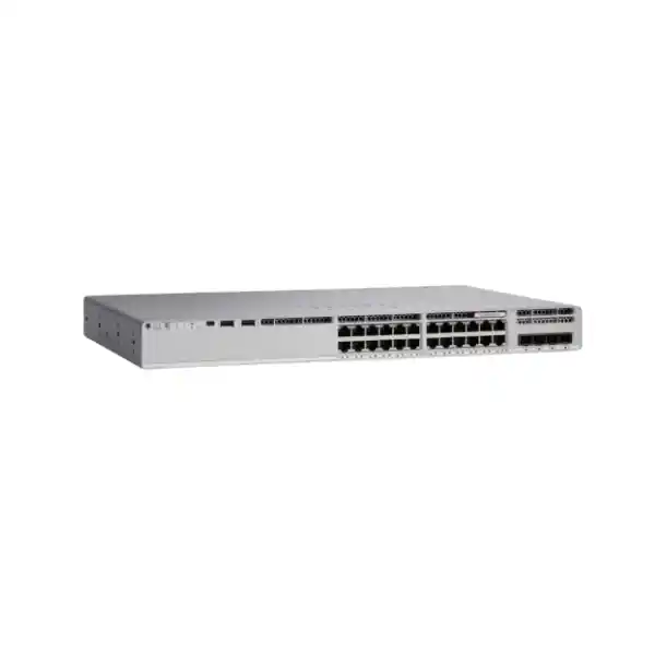
Cisco Catalyst C9200-24PB Network Switch
A 24-port full-PoE+ Catalyst 9200 platform built for organizations that need resilient access switching, enhanced virtual-network scale, modular uplink flexibility, Cisco IOS XE operations, and a practical path from conventional VLAN designs to policy-based segmentation and Cisco SD-Access.
Choose the C9200-24PB when your access layer needs 24 x 1G PoE+ ports, 32 virtual networks, modular 1G/10G/25G/40G uplinks, StackWise-class 160 Gbps stacking bandwidth, replaceable power and cooling components, and Network Advantage positioning for enhanced segmentation.
10/100/1000 copper downlinks with up to 30 W PoE+ per supported endpoint, subject to the available system power budget.
Enhanced VN scale differentiates the PB model from standard C9200 models designed around a smaller virtual-network count.
Stacking bandwidth supports a resilient multi-switch access block with simplified management and higher aggregate fabric capacity.
Field-replaceable network modules let the access layer evolve as distribution capacity and fiber standards change.
What the Cisco Catalyst C9200-24PB is designed to do
The Cisco Catalyst C9200-24PB is an enterprise access-layer switch for wired users, IP telephony, wireless access points, surveillance endpoints, building systems, thin clients, printers, workgroup devices, and other Ethernet-connected equipment that benefits from centrally managed switching and Power over Ethernet. The platform sits in the modular-uplink branch of the Catalyst 9200 family rather than the fixed-uplink C9200L branch. That distinction matters because the C9200-24PB can accept field-replaceable uplink modules, enabling a network team to start with lower-speed fiber or copper uplinks and move to 10, 25, or 40 Gigabit Ethernet without replacing the access chassis.
The “PB” model is particularly relevant where segmentation scale is a design requirement. Cisco positions the C9200-24PB and C9200-48PB as enhanced virtual-network models supporting 32 virtual networks. For architects evaluating Cisco SD-Access, VRF-based segmentation, or multi-department campus environments, this provides materially more segmentation headroom than standard C9200 variants that are specified for a smaller virtual-network count. This is not merely a marketing label: it affects how many logically separated network domains can be planned across a switching architecture and therefore should be considered early in a campus refresh rather than after deployment.
For UAE organizations, the C9200-24PB is well suited to branch offices, healthcare facilities, schools, hospitality properties, warehouses, retail networks, government sites, corporate floors, and mixed-use buildings where rack space is limited but network resiliency remains important. Its 1RU form factor, redundant field-replaceable fans, field-replaceable power architecture, modular uplinks, PoE+, and hardware-forwarded Layer 2/Layer 3 services create a balanced platform for sites that need enterprise operations without moving to a larger high-end campus switching family for every access closet.
Hardware and platform specifications at a glance
| Specification | C9200-24PB | Design implication |
|---|---|---|
| Downlinks | 24 × 10/100/1000 PoE+ copper | Supports conventional 1G enterprise edge endpoints and powered devices. |
| PoE power | 370 W with one 600 W AC PSU; up to 740 W with supported secondary PSU configuration | Power budget must be sized from real endpoint draw, not port count alone. |
| Uplink architecture | Modular | Uplink module can be selected independently from access-port configuration. |
| Uplink module choices | 4 × 1GE, 4 × 10GE, 2 × 25GE, or 2 × 40GE modules | Supports staged migration from legacy distribution to higher-speed aggregation. |
| Stacking bandwidth | 160 Gbps | Useful for resilient access stacks and simplified switch-domain operations. |
| Switching capacity | 128 Gbps standalone; 288 Gbps with stacking | Provides nonblocking-class access capacity appropriate to 24-port 1G edge designs with high-speed uplinks. |
| Forwarding rate | 95.23 Mpps standalone; 214 Mpps with stacking | Supports line-rate packet-forwarding requirements across typical access traffic mixes. |
| MAC scale | 32,000 MAC addresses | Provides substantial endpoint-learning headroom for enterprise access domains. |
| IPv4 total routes | 14,000 ARP plus learned routes | Supports routed access and branch Layer 3 designs within platform scale limits. |
| Virtual networks | 32 | Enhanced segmentation scale for policy-rich campus architectures. |
| Chassis dimensions | 1.73 × 17.5 × 13.8 in; approximately 4.4 × 44.5 × 35.0 cm | Standard 1RU rack deployment; allow added rear depth for field-replaceable components and cable bend radius. |
| Software | Cisco IOS XE; current Cisco licensing options should be matched to the ordered entitlement | Operational features depend on software release, license tier, and architecture. |
Twenty-four Gigabit Ethernet PoE+ access ports
The access side of the C9200-24PB is intentionally straightforward: twenty-four 10/100/1000BASE-T copper ports designed for common enterprise edge equipment. This makes the model appropriate when endpoint links are predominantly 1 Gigabit Ethernet rather than multigigabit. Typical devices include desk phones, desktop computers, printers, access-control panels, badge readers, point-of-sale systems, IP cameras, room schedulers, IoT gateways, environmental sensors, and wireless access points whose wired interface does not require more than 1 Gbps. Where a Wi-Fi 6E or Wi-Fi 7 deployment requires 2.5G, 5G, or 10G copper at the edge, a multigigabit Catalyst model should be evaluated instead of forcing a C9200-24PB into a role it was not designed to serve.
PoE+ support removes the need for individual AC adapters at many edge locations and centralizes power continuity around the network rack. That is operationally valuable in UAE offices, retail branches, clinics, campuses, hospitality environments, and warehouses where maintaining numerous local power bricks creates support overhead. A switch-backed UPS can keep phones, access points, cameras, and selected building systems online during brief power interruptions, provided the UPS itself is sized for the switch load, PoE draw, redundant power supplies, and any co-located equipment.
PoE design should always be calculated as a power budget, not as a statement that “all 24 ports are PoE+.” Each attached powered device negotiates or draws power according to its requirements, and the total available wattage depends on the installed switch power configuration. A site using twenty-four low-power IP phones may have abundant headroom with a single 600 W AC supply, while a surveillance or wireless-heavy closet can approach the 370 W single-supply PoE budget much sooner. FourTeck recommends capturing endpoint model, quantity, maximum requested power, expected average power, growth allowance, and criticality before selecting the final PSU and UPS design.
370 W single-PSU PoE planning
With the standard 600 W AC supply, Cisco specifies 370 W of available PoE power. That is enough for many mixed office access layers, but capacity should be checked against the real powered-device portfolio. For example, twelve endpoints engineered at 20 W each represent 240 W before growth reserve, leaving a materially different margin than twelve 30 W devices.
A professional bill of materials should distinguish switch system power from delivered PoE power and should include UPS efficiency, environmental derating considerations, and startup behavior where relevant.
Up to 740 W with additional supported power
Cisco specifies up to 740 W of available PoE power when the supported secondary power configuration is installed. On a 24-port switch, this creates enough aggregate budget to support a theoretical 30 W class load across all access ports with headroom at the switch power-budget level.
The secondary supply also contributes to platform resilience planning, but redundancy behavior and load-sharing objectives should be validated against the complete installed configuration rather than inferred from wattage alone.
Modular uplinks: one chassis, several distribution strategies
One of the strongest architectural reasons to select a C9200 modular-uplink SKU instead of a fixed-uplink access switch is the ability to choose the uplink personality independently. Cisco lists C9200 network modules with four 1 Gigabit Ethernet ports, four 10 Gigabit Ethernet ports, two 25 Gigabit Ethernet ports, or two 40 Gigabit Ethernet ports. This allows the same access chassis to be matched to very different distribution layers. A small branch can use lower-speed connectivity, a conventional campus can use redundant 10G fiber, a refreshed distribution block can use 25G, and an architecture with 40G aggregation can retain the access switch while changing only the uplink module and optics.
Uplink selection should be based on oversubscription, application traffic, east-west behavior, wireless aggregation, IP surveillance flows, local server access, backup windows, future growth, and failure-state bandwidth. A 24-port 1G access switch has a theoretical edge bandwidth of 24 Gbps in one direction if every port is simultaneously saturated, but real enterprise traffic rarely behaves as a continuous full-rate aggregate. The design question is therefore not simply “how many gigabits are on the front panel?” It is “what traffic must cross the uplink during the busiest period, and what happens when one uplink or one upstream device is unavailable?”
For many corporate floors, dual 10G uplinks provide a practical balance. High-density camera deployments, local storage, dense wireless aggregation, research environments, or large multi-switch access blocks can justify higher-speed uplinks. When migrating from 10G to 25G or 40G, optical transceiver choice, fiber type, patch-panel loss, distance, connector cleanliness, upstream port compatibility, and supported software combinations must all be validated. FourTeck can align the chassis, module, optics, fiber patching, stacking, and distribution interfaces as a single design rather than treating each component as an isolated line item.
Stacking architecture and 160 Gbps stack bandwidth
The C9200 platform supports 160 Gbps stacking bandwidth, which allows multiple compatible switches to operate as a coordinated access system. In practical campus operations, stacking can reduce the management burden associated with treating every physical access switch as a completely separate island. It can also simplify uplink resiliency, cross-stack EtherChannel designs, configuration consistency, software maintenance planning, and port expansion within an access closet.
Stack design is not only about aggregate bandwidth. Physical topology, stack member numbering, cable length, cable routing, rack position, power diversity, uplink placement, failure domains, and maintenance procedure all matter. A ring-style stack connection is generally preferable to a chain because it avoids creating a single cable break that divides the stack interconnect path. In multi-rack closets, available stack cable lengths and the physical route between cabinets should be verified before hardware is delivered. The stack should also be documented so field engineers can replace a member without accidentally altering the intended member numbering or uplink role.
Cisco specifies 128 Gbps switching capacity and 95.23 million packets per second forwarding for the standalone C9200-24PB. With stacking, Cisco lists 288 Gbps switch capacity and 214 Mpps forwarding. These figures indicate that the stack fabric contributes significant additional internal bandwidth and forwarding scale for multi-member operation. They should not be confused with uplink bandwidth: traffic leaving the access stack is still limited by the active uplink interfaces, optics, port-channel design, and upstream capacity.
A critical compatibility detail for the PB model is its enhanced virtual-network profile. Cisco notes that the 32-VN C9200-24PB-A and C9200-48PB-A SKUs are not intended to be stacked with standard C9200 models built around the four-VN profile. Therefore a brownfield expansion must validate the exact installed Catalyst models and SKUs, not merely the family name printed on the front panel. This is a common procurement point: a customer may say “add one C9200” while the technically correct request is “add a stack-compatible C9200-24PB-A with matching software and stack components.”
Enhanced segmentation: why 32 virtual networks matter
Modern access networks increasingly need to separate users and devices based on function, trust level, compliance requirement, tenant, building system, or operational ownership. Traditional VLANs remain useful, but large environments often need segmentation that extends beyond a single Layer 2 boundary. The C9200-24PB’s support for 32 virtual networks gives architects more room to represent meaningful security and routing domains within Cisco’s policy-driven campus architecture.
A virtual network can be used conceptually to isolate categories such as corporate users, finance, guest access, voice, cameras, physical security, facilities management, building automation, contractors, operational technology, laboratories, retail point-of-sale, clinical equipment, or third-party tenants. The exact mapping depends on the organization’s routing, identity, firewall, and SD-Access design. The important point is that segmentation is most effective when it reflects business risk and trust boundaries rather than simply reproducing historical VLAN numbers.
In a Cisco SD-Access deployment, segmentation can combine macro-level virtual networks with identity- and policy-based controls. The access switch becomes part of a broader intent-based architecture rather than acting only as a local VLAN bridge. This can reduce the operational complexity associated with manually extending VLANs across many closets, but it also introduces dependencies on architecture design, software versions, licensing, Cisco Catalyst Center or other supported management workflows, identity services, and routing underlay readiness.
Organizations that do not deploy SD-Access can still benefit from the C9200-24PB as a conventional enterprise switch. The presence of enhanced VN capability does not force an immediate fabric migration. It can instead be treated as strategic headroom: deploy a robust routed or VLAN-based access layer today, then preserve the option to adopt deeper segmentation later. For procurement teams, that is often preferable to choosing the lowest initial specification and discovering during a later security program that the access hardware constrains the target architecture.
Layer 2 scale
Cisco specifies up to 32,000 MAC addresses for C9200 models, 4094 VLAN IDs, 128 PVST instances, 13,000 STP virtual ports, and up to 512 switched virtual interfaces. These limits provide ample room for conventional enterprise access designs, though actual architecture should remain intentionally bounded and operationally supportable.
Large tables are not a reason to build unnecessarily large failure domains. Route where it improves convergence and policy clarity; bridge only where the application or service model requires it.
Layer 3 scale
Cisco lists 14,000 total IPv4 routes comprising ARP plus learned routes, with 4,000 IPv4 routing entries and 2,000 IPv6 routing entries for C9200 SKUs. The platform also supports multicast and policy scale appropriate to enterprise access roles.
Routed-access designs should still be validated against expected route growth, adjacency count, dynamic routing needs, multicast behavior, and the chosen software entitlement rather than relying on headline table values alone.
Hardware forwarding, ASIC behavior, and packet-processing expectations
Enterprise access switches are expected to forward ordinary Layer 2 and Layer 3 traffic in dedicated switching hardware rather than sending every packet through a general-purpose CPU. The C9200-24PB is engineered around this hardware-forwarding model, which is why Cisco publishes packet-forwarding and switching-capacity values independently from management-plane specifications. In normal operation, common forwarding decisions, VLAN handling, access control, quality-of-service classification, and supported routing functions are performed by the switching data path, while the CPU is reserved for control protocols, management, telemetry, exceptions, and process-level services.
Cisco’s public product data focuses on platform behavior and validated scale rather than requiring customers to design around a named merchant-silicon component. For practical network engineering, the relevant questions are whether a feature is supported in the installed software release and license, whether the required ACL, QoS, route, MAC, multicast, and segmentation scales fit the deployment, and whether the traffic pattern remains within the published platform capacity. Attempting to infer capability from an assumed ASIC identity is less reliable than engineering to Cisco’s published forwarding and scale specifications.
The 95.23 Mpps standalone forwarding figure is especially useful when comparing access switches with similar port counts because small-packet traffic can stress packet-processing capacity before raw gigabit throughput is exhausted. However, a campus design should not be reduced to a single Mpps number. Real performance depends on packet size distribution, active features, uplink design, congestion points, queueing policy, endpoint behavior, traffic bursts, and the upstream network. The correct approach is to use published platform performance as one input within a complete capacity model.
Jumbo-frame support up to 9198 bytes is valuable for environments where larger frames are intentionally used, but every path component must support the configured MTU. A mismatch among endpoints, switch SVIs, routed links, firewalls, storage systems, virtualization hosts, or WAN devices can produce fragmentation or black-hole symptoms that are difficult to diagnose. For ordinary user access, standard Ethernet MTU remains the simplest choice unless a specific application requires otherwise.
Power resilience, field-replaceable components, and rack design
The C9200-24PB uses field-replaceable power supplies and redundant field-replaceable fans. This is an important distinction in enterprise environments because a failed fan or PSU can be serviced without replacing the entire switch chassis. It also allows the network team to align power architecture with site criticality. A small noncritical branch may accept a single PSU and a robust UPS, while a hospital floor, security network, or 24-hour operation may justify dual power supplies fed from appropriately independent power paths where the building infrastructure supports it.
Redundancy should be engineered end to end. Installing two power supplies but connecting both to the same PDU, the same UPS output, or the same upstream electrical circuit does not provide the same resilience as genuinely diverse sources. Likewise, dual switch uplinks that terminate on one distribution chassis may protect against an optic failure but not a distribution-device failure. FourTeck therefore recommends documenting each failure scenario—PSU, PDU, UPS, stack cable, access member, fiber strand, transceiver, distribution port, and distribution device—and confirming the expected service state after each event.
The chassis is approximately 1.73 inches high by 17.5 inches wide by 13.8 inches deep before accounting for the added rear depth of installed field-replaceable components. Rack planning should reserve not only 1RU but also adequate rear clearance for the power supplies, fan airflow, power leads, stack cables, uplink fibers, bend radius, and service access. In shallow wall cabinets, the nominal chassis depth alone can be misleading; the complete installed depth and door clearance should be checked against the actual cabinet.
UAE deployments also need thermal discipline. Network closets should have reliable cooling, clean airflow, controlled dust, and enough separation to avoid hot-air recirculation. A switch that is technically rated for enterprise operation still depends on the room remaining inside its environmental specifications. In warehouses, back-of-house retail areas, temporary offices, and older buildings, cabinet ventilation and ambient temperature often deserve as much attention as the switch model itself.
Cisco IOS XE operations and software lifecycle
The Catalyst 9200 family runs Cisco IOS XE, giving network teams a familiar operational model for command-line configuration, routing and switching protocols, software image management, programmability, telemetry, security functions, and centralized management integrations. For organizations standardizing on Cisco access switching, operational consistency can be as valuable as raw port specifications because engineers can reuse proven templates, monitoring workflows, change procedures, troubleshooting practices, and automation tooling across multiple sites.
Software version selection should follow a controlled lifecycle. Newest is not always the same as best for a production network. A release should be chosen based on Cisco support guidance, required feature set, known caveats, security advisories, interoperability with Catalyst Center or other management tools, optic and module support, stack compatibility, and the organization’s maintenance policy. In a stacked deployment, members should operate on a compatible image strategy and upgrade plan so that a replacement unit does not introduce avoidable version mismatch during a maintenance event.
Configuration management should be treated as part of the product design. At minimum, an enterprise deployment should define secure administrative access, AAA, management VRF or management network strategy, NTP, DNS where required, SNMP or model-driven telemetry, syslog, configuration backup, software image repository, local fallback credentials, spanning-tree policy, port security posture, DHCP snooping where appropriate, Dynamic ARP Inspection dependencies, QoS policy, PoE monitoring, interface descriptions, and standardized naming conventions.
Automation can reduce errors across dozens or hundreds of switches, but template variables must be carefully controlled. Site code, management IP, uplink interface, VLAN or VRF IDs, stack member roles, port profiles, local addressing, and device credentials should be parameterized rather than manually edited after deployment. A repeatable “golden configuration” is particularly valuable for UAE organizations with many retail branches, clinics, schools, or offices because it reduces configuration drift and accelerates replacement after hardware failure.
Licensing: match the entitlement to the intended architecture
Cisco’s current Catalyst 9200 documentation describes more than one licensing path, including unified switching licensing through Cisco Networking Subscription as well as Cisco DNA licensing options. Cisco also identifies the C9200-24PB-A ordering model as a 24-port PoE+ enhanced-VRF switch associated with Network Advantage. Because licensing programs evolve, the exact subscription, entitlement, term, support coverage, and management capabilities should be confirmed at the time of quotation rather than copied from an older bill of materials.
This matters because customers often focus on the chassis code while treating software as a secondary item. In reality, the desired operating model may depend on an Advantage-level feature set, a subscription term, centralized assurance, automation, segmentation, or support entitlement. A switch purchased with the wrong software package can still be physically correct but commercially or functionally misaligned with the intended deployment.
A quotation request should therefore identify whether the switch will be used as traditional Layer 2 access, routed access, part of an SD-Access fabric, centrally managed by Cisco Catalyst Center, integrated with identity-based policy, or monitored through another supported management approach. It should also specify the required support period and whether the organization prefers subscription alignment with an existing Cisco agreement. This prevents a common procurement failure: receiving the correct hardware but discovering later that the license term or tier does not match the rollout plan.
FourTeck can help translate the technical architecture into an orderable bill of materials. That process includes the switch SKU, uplink network module, optics, stack hardware, PSU choice, power cords, software entitlement, support coverage, rack accessories, console requirements, and deployment services. For broader UAE infrastructure planning, customers can also review FourTeck IT Services UAE for implementation and operational support options.
Security controls at the access layer
The access switch is one of the most important enforcement points in an enterprise network because it is where users, phones, cameras, access points, printers, and unmanaged devices first connect. A secure C9200-24PB deployment should therefore begin with an explicit port trust model. User-facing ports should not inherit the same assumptions as uplinks, access-point trunks, voice ports, security-camera ports, or building-system interfaces. Each port type should have a defined authentication, VLAN or virtual-network assignment, QoS treatment, PoE behavior, and exception process.
Identity-based access can be built around IEEE 802.1X, MAB for devices that cannot perform 802.1X, and centralized policy systems such as Cisco Identity Services Engine where the broader architecture supports it. The goal is to avoid relying solely on physical port location as proof of trust. A device connected to an office jack should receive access according to identity and policy, not because the jack happens to be on a “trusted floor.”
Layer 2 protection features can further reduce common local-network risks when deployed correctly. DHCP snooping can establish trusted DHCP paths and build binding information; Dynamic ARP Inspection can use trusted binding data to detect invalid ARP behavior; IP Source Guard can constrain source addressing; BPDU Guard can help protect edge ports from accidental or malicious spanning-tree participation; storm control can limit certain broadcast, multicast, or unknown-unicast conditions. These controls must be designed carefully because misapplied trust boundaries can disrupt legitimate services.
Control-plane and management security are equally important. Administrative access should use secure protocols, centralized AAA where available, role-based privilege, logging, configuration-change accountability, secure time synchronization, and restricted management-plane reachability. Management interfaces should not be exposed broadly to user VLANs. Unused ports should be administratively disabled or placed in a controlled state, and port descriptions should accurately identify connected systems to accelerate incident response.
Segmentation then provides the larger architectural boundary. A camera network does not necessarily need direct reachability to finance users; guest devices do not need visibility into internal services; building-management controllers should have tightly defined paths to management servers. The C9200-24PB’s enhanced VN scale is valuable because it allows security policy to be reflected in the network design without forcing unrelated device classes into the same routing domain simply to conserve segmentation capacity.
QoS for voice, video, wireless, and business applications
Quality of Service becomes important when links can experience congestion or when latency-sensitive traffic shares the network with bulk transfers. The C9200-24PB can participate in an end-to-end QoS design that recognizes trusted markings from appropriate devices, classifies traffic where trust is not appropriate, places traffic into suitable queues, and preserves priority behavior toward the distribution and WAN layers. The objective is not to make every application “high priority”; it is to define a small number of traffic classes that reflect measurable business needs.
IP telephony is the classic example. Voice media typically needs low latency, low jitter, and low loss, while phone signaling has different requirements. Video conferencing may be interactive but consumes more bandwidth. Wireless traffic can carry many application types over one access-point link. Backup jobs, software distribution, cloud synchronization, large file transfers, and guest traffic can be allowed to use spare capacity without being permitted to starve real-time services during congestion.
QoS must be consistent across the path. A perfectly marked packet at the access switch can still suffer if the distribution layer, firewall, WAN edge, SD-WAN device, or service-provider handoff ignores or rewrites the policy. Conversely, blindly trusting endpoint markings can allow ordinary clients to claim priority they do not deserve. A well-engineered design establishes trust boundaries, classifies traffic at the correct point, documents DSCP handling, and verifies queue behavior under load.
For PoE voice deployments, the physical and logical designs intersect. The switch powers the phone, places it in the correct voice policy, preserves business-PC access through the phone where used, applies QoS, and keeps the service running through UPS-backed power. Treating these as separate configuration tasks misses the real objective: delivering a predictable voice experience during both normal traffic and partial failures.
Deployment topology 1: resilient corporate access stack
A common enterprise design uses two or more C9200-24PB switches in a stack serving a floor or department. Endpoints are distributed across stack members, while uplinks are placed on different members and bundled toward redundant distribution switches. This gives the access layer multiple layers of resilience: failure of one access member affects only the ports physically attached to that member, while the remaining stack can continue forwarding; failure of one uplink can be absorbed by the port-channel; and a single PSU issue can be mitigated where redundant power has been correctly designed.
For this topology, uplink bandwidth should be selected based on aggregate floor traffic and the failure state. If two 10G uplinks normally carry traffic, the design should confirm whether one surviving 10G path is sufficient during maintenance or a fault. If not, 25G or 40G uplinks may be justified. The access stack should also be split across electrical circuits where available, and endpoints that provide redundant service—such as access points across overlapping cells or redundant controllers—can be distributed across different stack members.
Operationally, the stack should use standardized member numbering, clear rack labels, documented cable topology, and interface descriptions tied to patch-panel ports and room locations. This greatly reduces repair time. A technician replacing switch member 2 should be able to identify the correct chassis, power feeds, stack cables, uplink module, and access patching without reverse-engineering the closet during an outage.
Deployment topology 2: secure branch with local Layer 3 switching
In a branch office, the C9200-24PB can serve as the primary access switch behind a firewall, SD-WAN appliance, or WAN router. User, voice, wireless, guest, printer, CCTV, and facilities networks can be separated into VLANs or routed segments. Depending on the architecture and entitlement, selected inter-VLAN routing can occur on the switch while north-south security policy remains enforced by the firewall. This avoids sending every local packet through an undersized WAN or security appliance while preserving explicit security boundaries.
The design should decide intentionally where the default gateways live. If all gateways are on the firewall, policy is centralized but east-west traffic may consume firewall capacity. If gateways are on the switch, local routing is efficient but the network team must ensure that sensitive inter-segment traffic is still inspected or restricted using the appropriate control model. Hybrid designs are also possible, with trusted operational segments routed locally and sensitive boundaries enforced through the firewall.
For a branch with a small number of servers or appliances, redundant 10G uplinks may be more than sufficient. A branch with local virtualization, video recording, or high-volume replication may need more. The modular uplink design lets the switch evolve as the branch grows. Customers planning broader server-room upgrades can reference FourTeck Server Dubai to coordinate switching, server, rack, UPS, and connectivity requirements rather than treating the LAN as an isolated purchase.
Deployment topology 3: surveillance and physical-security access
IP surveillance is a natural use case for PoE access switching, but it is also one of the easiest environments to undersize. Cameras may draw significant PoE power, generate continuous upstream traffic, and require long retention through network video recorders or central storage. Before using the C9200-24PB for cameras, calculate both power and bandwidth. A 370 W single-PSU PoE budget can support many cameras, but the exact count depends on each camera’s requested power, infrared illuminators, heaters, pan-tilt-zoom motors, and environmental features.
Bandwidth sizing should use expected bitrate rather than camera resolution alone. Codec, frame rate, scene complexity, VBR behavior, analytics, audio, and recording profile all influence traffic. Twenty-four cameras averaging 8 Mbps produce roughly 192 Mbps of steady video before overhead, which is easy for Gigabit access ports but may become more significant across many stacked switches feeding centralized recorders. During firmware updates, live viewing, export, or failover, traffic patterns can change.
Security networks should usually be isolated from ordinary users. Cameras need reachability to management, time, DNS where required, recording platforms, and monitoring systems—not unrestricted access to every business subnet. Administrators should also prevent unused camera ports from becoming convenient entry points for unauthorized devices. The enhanced segmentation scale of the C9200-24PB gives architects room to separate physical security, access control, building management, and general enterprise traffic.
Power continuity is often the hidden requirement. If cameras are expected to record during a short utility outage, the switch, recorder, storage, and network path all need UPS-backed power. Providing PoE from a resilient rack simplifies this compared with distributed camera power adapters, but only if the UPS runtime calculation includes the actual PoE load.
Deployment topology 4: campus migration toward Cisco SD-Access
Organizations moving from conventional campus networking toward Cisco SD-Access need an access platform that can participate in the target architecture without forcing every migration step to occur at once. The C9200-24PB’s enhanced 32-VN profile is specifically relevant to segmentation-heavy SD-Access designs. A phased strategy can refresh access hardware first, standardize software and management, improve identity controls, and later introduce fabric roles when the underlay, Catalyst Center, identity services, routing, and policy model are ready.
The preparation stage is often more important than the cutover. Existing VLANs should be inventoried and mapped to business functions. Duplicate or obsolete networks should be removed. IP addressing should be reviewed for summarization and growth. Authentication exceptions should be cataloged. Legacy devices that cannot support modern access control should be identified. Wireless architecture, DHCP, DNS, NTP, AAA, PKI, multicast, and firewall dependencies should all be documented before building policy.
Virtual-network design should remain understandable. The fact that the PB model supports 32 VNs does not imply that all 32 should be used. Each VN introduces operational and policy context. The objective is to create enough macro-segmentation to separate meaningful trust zones while using identity-based policy for finer distinctions where appropriate. A smaller set of well-defined VNs is often more supportable than a large number created around organizational chart details that change frequently.
Compatibility is essential in stacked environments. Because Cisco specifically calls out the 32-VN PB models as a distinct stacking profile relative to four-VN C9200 models, an SD-Access migration should inventory every stack member by exact SKU. This avoids discovering during rollout that a planned mixed stack is unsupported or operationally unsuitable.
How to size the C9200-24PB for a real site
Start with endpoint count, but do not stop there. Count every current copper device, then identify how many require PoE, how many are expected to need multigigabit speeds, how many are likely to be added during the switch’s lifecycle, and which devices must remain online after a component failure. A 24-port switch with 22 occupied ports on day one is normally a poor design unless expansion is intentionally handled by a second stack member. Practical headroom reduces emergency patching and preserves flexibility for temporary devices, replacement testing, new access points, or office changes.
Next, calculate PoE. For each device class, capture maximum power request rather than using an informal estimate. Multiply by quantity, then include an engineering reserve. Compare the result against the 370 W single-PSU budget and supported higher-power configurations. If the switch will power safety, security, or communications systems, determine whether dual power and UPS runtime are required. A PoE budget that fits on paper can still fail operationally if the UPS is not sized for the delivered load.
Then calculate uplink demand. Use observed utilization from the existing network where available. Include peak periods, backup traffic, video flows, wireless aggregation, software distribution, internet breakout location, local server traffic, and the expected failure state. Choose the network module based on this model and the upstream switch capability. Avoid selecting 25G or 40G merely because it is available; higher speeds can require different optics, fiber plant, and distribution interfaces. Equally, avoid saving a small amount on a 1G uplink module if the site already approaches that bandwidth during normal operations.
Finally, size software and segmentation. Count required VLANs, VRFs or virtual networks, routed interfaces, routing adjacencies, ACL entries, multicast requirements, authentication sessions, and management integrations. The published C9200 scales are generous for ordinary access roles, but unusual deployments—large IoT fabrics, dense multicast, highly segmented facilities, or route-heavy branch architectures—should be validated more carefully.
The result should be a complete design statement: number of switches, stack topology, PoE requirement, PSU configuration, UPS load, uplink module, optic types, fiber path, upstream switch ports, license tier and term, support, rack position, management addressing, software release, configuration template, and migration method. This is the level of detail that turns a switch purchase into a predictable deployment.
C9200-24PB vs C9200-24P: the practical difference
Both the C9200-24PB and C9200-24P provide 24 full-PoE+ 1G copper downlinks and use modular uplinks. Both share the same published standalone switching capacity of 128 Gbps and forwarding rate of 95.23 Mpps. Both can use a 600 W AC power supply with 370 W available PoE power in a single-primary configuration. At a superficial hardware level, they can therefore look very similar.
The main architectural distinction is segmentation and the enhanced model profile. Cisco specifies the C9200-24PB for 32 virtual networks, while the standard C9200-24P is in the group specified for four virtual networks. Cisco’s ordering information identifies C9200-24PB-A as the 24-port PoE+ enhanced-VRF, Network Advantage model. This makes the PB model the stronger choice when the network roadmap includes broader SD-Access segmentation or a larger number of isolated routing domains.
Stack compatibility is another important consequence. Cisco notes that the PB 32-VN models should not be stacked with the standard four-VN C9200 profile. Therefore the decision between 24P and 24PB is not just about a feature that can be ignored until later. It affects how a stack can be expanded and how replacement spares should be planned.
If a site needs ordinary secure access switching with a small segmentation model, the C9200-24P may be sufficient. If the site is part of an enterprise standard that expects enhanced VRF or VN scale, the C9200-24PB is the more strategic selection. The cost comparison should therefore include lifecycle architecture, not only chassis price.
C9200-24PB vs multigigabit C9200 models
The C9200-24PB provides twenty-four 1G copper downlinks. This is ideal for conventional enterprise endpoints but should not be mistaken for a multigigabit access switch. Cisco offers C9200 multigigabit variants for environments that need 2.5G, 5G, or 10G copper on selected access ports. Those models are often better suited to high-performance Wi-Fi access points or specialized workstations whose edge bandwidth exceeds 1 Gbps.
Choosing between PB and multigigabit models requires balancing segmentation against edge speed. If the priority is 32 virtual networks and the endpoint base is 1G, the C9200-24PB is compelling. If the priority is high-speed copper for wireless convergence, a PXG-class model may be more appropriate. In a large campus, both can coexist by closet or endpoint requirement rather than forcing one universal model everywhere.
A wireless refresh is therefore a key trigger for design review. An existing access point may operate adequately on 1G today, while its replacement could include multigigabit Ethernet and a higher PoE requirement. Buying new 1G access switches just before a major Wi-Fi upgrade can create an avoidable bottleneck. FourTeck recommends aligning wired access procurement with the wireless roadmap for at least the expected switch lifecycle.
UAE procurement and deployment considerations
Enterprise switching projects in the UAE often span more than a single building. A customer may have Dubai headquarters, Abu Dhabi offices, warehouses in Jebel Ali, retail branches across multiple emirates, and regional operations elsewhere in the Gulf or Africa. Standardizing on a known switch family can simplify spares, configuration templates, monitoring, and engineer training, but the bill of materials should still be adapted to each site’s port density, rack environment, fiber plant, and power quality.
Lead time and exact SKU control are important. Procurement documents should specify C9200-24PB rather than accepting a generic “24-port Cisco PoE switch” substitution. Uplink module, optics, stack accessories, PSU, license tier, support entitlement, power-cord type, and any spare components should be listed explicitly. This prevents receiving a switch chassis that cannot be commissioned because the correct uplink module or optics are missing.
For brownfield sites, an audit should precede ordering. Record existing switch models, software versions, stack configuration, transceivers, fiber type, patch-panel connector, port utilization, PoE consumption, VLANs, routing, spanning tree, authentication, QoS, management platform, UPS load, and rack depth. The audit often reveals that the biggest risk is not the switch replacement itself but an undocumented dependency such as a legacy access-control panel, a hard-coded trunk, an old fiber link, or an endpoint that cannot authenticate.
For organizations looking for an integrated UAE supplier and deployment partner, FourTeck UAE can coordinate network switching with broader infrastructure requirements. For multinational architecture and sourcing, FourTeck Global provides a broader reference point, while customers expanding into African markets can use FourTeck Africa for regional technology requirements.
Environmental planning is especially relevant in hot climates. The switch belongs in a controlled communications room or properly ventilated cabinet, not an unconditioned space simply because the network closet is physically convenient. Power conditioning, UPS autonomy, earthing, cable management, dust control, and preventive maintenance contribute directly to network availability. A well-engineered rack can extend the operational value of the switching investment far more than a chassis-only procurement approach.
Migration methodology for replacing an existing access switch
A low-risk migration begins with discovery. Export the existing configuration, capture interface status, MAC tables, PoE draw, LLDP/CDP neighbors, spanning-tree state, EtherChannels, VLAN assignments, port descriptions, authentication settings, routing adjacencies, static routes, DHCP snooping bindings where relevant, and monitoring dependencies. Compare the observed state with documentation, because the live network often contains years of undocumented changes.
Next, rationalize rather than blindly clone. Shut ports that have been unused for a long period, remove obsolete VLANs where safe, correct descriptions, identify nonstandard configurations, and map each endpoint type to a standard port profile. A migration is an opportunity to reduce technical debt. Copying every historical exception to a new switch recreates old problems on new hardware.
Build and stage the C9200-24PB before the outage. Install the intended IOS XE release, establish secure management, apply the baseline configuration, configure stack members, validate uplink modules and optics, prebuild VLANs or virtual networks, load routing and QoS policy, configure AAA, and verify logs and monitoring. Where possible, perform a bench test using representative endpoints such as an IP phone, access point, camera, and authenticated workstation.
During cutover, move uplinks and endpoint patching according to a documented port map. Verify spanning-tree and port-channel state before moving large numbers of endpoints. Check PoE delivery, voice registration, wireless AP joins, DHCP, DNS, routing, internet access, internal applications, printing, surveillance recording, and management telemetry. If the change includes new segmentation, validate both permitted and denied traffic so that security policy is tested rather than assumed.
After the migration, preserve the rollback configuration until the acceptance criteria are met. Capture a new baseline, archive the final configuration, update rack drawings and port schedules, document software and licenses, record optic serials if required by the organization, and update monitoring inventory. This turns the installation into an operationally supportable service rather than a one-night hardware swap.
Monitoring, telemetry, and proactive operations
An access switch should be monitored for more than reachability. Useful operational signals include interface utilization, errors, discards, duplex or speed anomalies, optic levels where supported, stack state, CPU and memory trends, environmental alarms, fan and PSU status, PoE consumption, temperature, spanning-tree changes, port-channel member state, authentication failures, routing neighbor state, syslog severity, configuration changes, and software-image compliance.
PoE monitoring is particularly valuable because power consumption can change when endpoints are replaced. A closet that originally powered phones may later host cameras or new access points, gradually eroding power headroom. Trending total and per-port PoE draw helps identify when a secondary PSU or redistribution of powered devices should be planned before an outage or upgrade forces the issue.
Interface error counters can expose cabling faults that users perceive as application problems. CRC errors, flaps, excessive drops, or negotiated-speed changes should be investigated rather than cleared without root-cause analysis. In a structured-cabling environment, switch telemetry can help isolate whether the fault follows the endpoint, patch lead, patch-panel path, or switch port.
Configuration drift is another operational risk. Standardized templates, version control, scheduled backups, and automated compliance checks can reveal unauthorized or accidental changes. For large fleets, the network should be managed as a system of controlled state rather than as dozens of individually handcrafted switches.
Availability engineering beyond the switch chassis
A highly available access design is a chain whose strength is determined by the weakest dependency. Redundant switch fans and power supplies are valuable, but service can still fail because of a single UPS, single distribution switch, single fiber pair, single DHCP server, single authentication service, or single upstream firewall. Availability planning should therefore map the full dependency path for critical endpoint classes.
For IP phones, consider switch power, UPS, call-control reachability, DHCP, DNS, and WAN redundancy. For wireless access points, include switch PoE, uplink capacity, wireless controller or cloud reachability, RADIUS, DHCP, and DNS. For cameras, include PoE, recording server, storage, network path, time source, and operator viewing stations. This service-centric approach produces better outcomes than evaluating each infrastructure device in isolation.
Maintenance is part of availability. The ability to replace a field-replaceable PSU or fan without replacing the chassis can reduce disruption, but only if spares or support logistics are available. A stack can preserve service during a member failure, but only if endpoints are physically distributed according to business criticality. Dual uplinks can provide path resilience, but only if they terminate in a properly designed upstream architecture.
Documented recovery procedures are therefore essential. Operations staff should know how to identify a failed stack member, replace a PSU, validate a new switch member, restore configuration, confirm stack role, test uplinks, and verify critical endpoint services. A resilient design that nobody knows how to recover remains operationally fragile.
Common specification mistakes to avoid
Mistake 1: assuming PoE+ means unlimited power
PoE capability is constrained by the installed system power budget. Calculate endpoint demand and growth instead of multiplying port count by a marketing maximum and assuming the chassis can always supply it.
Mistake 2: forgetting the uplink module
The C9200-24PB uses modular uplinks. A chassis order without the correct network module, optics, and upstream compatibility can delay commissioning even when the switch itself arrives on time.
Mistake 3: mixing incompatible stack profiles
The enhanced 32-VN PB models have a distinct stacking consideration relative to standard four-VN C9200 models. Check exact SKUs before expanding an existing stack.
Mistake 4: treating 1G access as future-proof for every endpoint
The PB model is 1G on its copper access ports. If future wireless or workstation designs need multigigabit copper, evaluate the appropriate C9200 multigigabit variant before standardizing.
Mistake 5: ordering hardware before licensing is defined
The intended software tier, subscription path, support term, and management architecture should be part of the BOM from the beginning, especially for enhanced segmentation and centralized operations.
Mistake 6: ignoring rack and power reality
Verify installed depth, rear clearance, PDU outlets, UPS capacity, cooling, fiber bend radius, and cable management. A correct switch can still be a poor fit for an undersized cabinet.
Optics and fiber planning for the modular uplink
Selecting a 10G, 25G, or 40G network module is only the first step in uplink design. The complete optical path must be compatible end to end. Engineers should identify fiber type, strand count, connector type, patch-panel layout, distance, existing transceivers, upstream switch model, supported optic matrix, and any intermediate passive components. Older buildings may have multimode fiber that supports one speed over the required distance but not another, while newer backbone links may use single-mode fiber with a different optic family.
For short in-rack or same-room connections, direct-attach or appropriate short-reach solutions may simplify deployment where supported. For building risers or campus links, optical transceivers are more common. The design should preserve fiber polarity and labeling, keep connectors clean, respect bend radius, and measure the link where there is uncertainty about plant condition. A 25G or 40G upgrade can expose marginal fiber that appeared stable at lower speeds.
Redundant uplinks should ideally use physically diverse paths where the building allows it. Two fibers in the same cable tray protect against an optic or port failure but not against a cut cable. For critical sites, route diversity, distribution-switch diversity, and power diversity should be coordinated. This is especially relevant in campuses, warehouses, and multi-floor towers where maintenance activity can create physical risk to shared pathways.
Optic procurement should follow Cisco compatibility guidance for the selected module and IOS XE release. Third-party optics may have commercial or operational implications that should be understood before deployment. The safest bill of materials records the exact network module and exact transceiver types on both ends of every uplink rather than leaving “10G fiber” as an unspecified line item.
Lifecycle value and investment protection
Access switches often remain in service for many years, so lifecycle flexibility matters more than the first-day port count. The C9200-24PB supports several forms of investment protection. Modular uplinks let the distribution connection evolve independently of the copper edge. Field-replaceable fans and power supplies reduce the need to replace a whole chassis after certain component failures. Stacking lets a closet expand by adding compatible members. Enhanced segmentation capacity gives the network team room to adopt a richer policy model later.
The largest lifecycle risk is usually not hardware obsolescence but architectural mismatch. A switch can remain reliable yet become unsuitable because new access points need multigigabit links, security policy requires more segmentation, an upstream refresh changes optic standards, or management strategy shifts toward centralized assurance and automation. The PB model addresses some of these risks—especially segmentation and uplink evolution—but not all. This is why endpoint roadmap and wireless roadmap should be reviewed before standardizing the access layer.
Lifecycle planning should also include software support, security updates, subscription renewal, spare strategy, and replacement procedure. Organizations with many sites may keep a small number of preconfigured spare switches or maintain rapid hardware support. Spares should match the stack profile and required uplink architecture. A generic spare from the same family may not be suitable if its VN scale or module layout differs.
When lifecycle cost is evaluated properly, the purchase price is only one component. Engineering time, downtime risk, license term, support, optics, power, rack work, cabling, migration labor, monitoring, and future expansion all contribute. A design that costs slightly more initially can be substantially cheaper over its service life if it avoids a premature access-layer replacement.
Frequently asked technical questions
Does the C9200-24PB support PoE+ on all 24 access ports?
Yes. Cisco identifies it as a 24-port full-PoE+ model. Actual simultaneous power delivery is governed by the installed PoE power budget and the connected devices’ negotiated requirements.
What is the single-PSU PoE budget?
With the 600 W AC primary supply, Cisco specifies 370 W of available PoE power. Supported additional power configurations can raise available PoE power to 740 W.
Can the uplink speed be changed later?
The chassis uses field-replaceable uplink network modules. Cisco lists 4 × 1GE, 4 × 10GE, 2 × 25GE, and 2 × 40GE module options for modular C9200 models, subject to compatibility and optics.
Is the access side multigigabit?
No. The C9200-24PB provides 10/100/1000 copper downlinks. Choose a C9200 multigigabit model if selected endpoints require 2.5G, 5G, or 10G copper access.
How many virtual networks are supported?
Cisco specifies 32 virtual networks for the C9200-24PB and C9200-48PB enhanced-VN models, providing more segmentation scale than standard C9200 models in the four-VN group.
Can a PB model be added to any C9200 stack?
No. Exact compatibility must be checked. Cisco specifically notes that the 32-VN C9200-24PB-A and C9200-48PB-A models cannot be stacked with standard C9200 models in the four-VN profile.
What is the switching capacity?
Cisco specifies 128 Gbps standalone switching capacity and 288 Gbps switch capacity with stacking for the C9200-24PB.
What forwarding rate does Cisco publish?
The standalone C9200-24PB is specified at 95.23 Mpps, with 214 Mpps published for the platform when operating with stacking.
Is a second power supply mandatory?
No. The chassis can operate with its supported primary power supply. A second supply is selected when additional PoE capacity, power resilience, or both are required by the design.
Is Cisco Catalyst Center mandatory for basic switch operation?
No. The switch can be operated as a conventional Cisco IOS XE enterprise switch. Centralized platforms can add automation, assurance, and fabric workflows where the organization chooses to use them.
Does it support IPv6 routing entries?
Cisco publishes a scale of 2,000 IPv6 routing entries for C9200 SKUs. Feature use must still be aligned to the software release and license.
Who should choose this model?
Organizations needing 24 × 1G PoE+ ports plus enhanced segmentation, modular high-speed uplinks, stacking, and field-replaceable power and cooling are strong candidates.
Decision recap: when the C9200-24PB is the right access switch
The C9200-24PB is a strong fit when the access layer is dominated by 1G copper endpoints, PoE+ is required across up to 24 ports, and the network roadmap values stronger segmentation scale than a standard C9200 profile. Its 32 virtual networks, 160 Gbps stacking bandwidth, modular uplinks up to 40G, dual field-replaceable power capability, replaceable cooling, and Cisco IOS XE operating model make it suitable for enterprise closets that need to remain flexible over a long lifecycle.
It is less suitable when the primary requirement is multigigabit copper at the access edge. In that case, evaluate C9200 multigigabit models. It may also be unnecessary for a very small branch that needs only basic Layer 2 access and fixed uplinks. The best choice depends on the entire design—endpoint speed, PoE load, segmentation, uplinks, stacking, management, software, and expansion—not on port count alone.
24-port 1G PoE+ enterprise access, enhanced VN segmentation, modular uplinks, resilient stacks, and future SD-Access planning.
Exact license entitlement, uplink module, optics, PoE power, stack compatibility, power cords, rack depth, and software release.
Your wired access points require 2.5G/5G/10G copper, your port density is better served by 48-port models, or your segmentation needs are minimal.
Quotation input checklist for an accurate Cisco C9200-24PB BOM
Providing the following information allows FourTeck to quote a complete, deployment-ready solution instead of a chassis-only line item. The checklist also reduces the chance of incorrect optics, inadequate PoE capacity, incompatible stack expansion, or mismatched licensing.
Number of switches, building or branch location, rack count, and whether the switches are standalone or part of a stack.
Exact current Catalyst SKUs, stack member count, software version, stack cable type and length, and any planned mixed-model expansion.
Quantity and model of IP phones, access points, cameras, door systems, IoT devices, and their maximum or negotiated power requirements.
Required 1G, 10G, 25G, or 40G uplink speed; number of links; LACP design; and upstream switch model.
Multimode or single-mode fiber, distance, connector type, patch-panel details, and any known existing transceiver models.
Whether dual PSUs, diverse PDUs, UPS runtime, redundant uplinks, redundant distribution switches, or spare chassis are required.
Current Cisco agreement, desired entitlement tier, subscription term, Catalyst Center use, SD-Access roadmap, and support requirement.
Number of VLANs, VRFs or virtual networks, identity-policy requirements, guest design, IoT separation, and routed-access needs.
Rack depth, available RU, PDU outlet type, UPS capacity, cooling condition, cable-management space, and preferred power-cord standard.
Whether FourTeck should provide audit, staging, configuration, rack installation, cutover, testing, documentation, or post-deployment support.
Final consultation panel: build the access layer as a complete system
The Cisco Catalyst C9200-24PB is more than a 24-port PoE switch. Its value comes from how the chassis, enhanced segmentation profile, 160 Gbps stacking, modular uplinks, PoE power architecture, IOS XE software, licensing, optics, cabling, and upstream network are assembled into a coherent design. FourTeck can help UAE customers validate the full bill of materials and implementation plan before purchase, reducing the risk of missing modules, insufficient PoE capacity, unsupported stack combinations, fiber mismatches, or licensing surprises.
For a new deployment, provide endpoint count, PoE requirements, uplink target, site topology, rack details, segmentation goals, and required support term. For a replacement project, add the current switch models, configurations, software versions, optic inventory, and port-utilization data. The result can then be sized around real traffic and failure scenarios rather than assumptions.
A well-planned C9200-24PB deployment can deliver a stable foundation for office users, voice, wireless, surveillance, building systems, and policy-based segmentation while preserving a path to faster uplinks and more sophisticated campus architecture. The right question is not simply whether the switch has enough ports today, but whether its power, segmentation, uplinks, resiliency, software, and operational model fit the network the organization expects to run over the coming years.

Reviews
There are no reviews yet.