
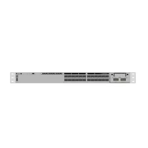
Cisco Catalyst C9300-24S Network Switch
A 24-port 1G SFP member of the Cisco Catalyst 9300 modular-uplink family, engineered for resilient fiber access, campus distribution, secure segmentation, scalable uplinks, and stack-based operations. For UAE organizations standardizing on Cisco IOS XE, the C9300-24S provides a practical way to terminate large numbers of optical building, floor, industrial, or remote-cabinet links while retaining enterprise routing, telemetry, automation, and high-availability capabilities.
Fiber-facing Gigabit Ethernet access interfaces for SFP optics and supported media choices.
High-speed stack fabric for modular-uplink C9300 designs with up to eight compatible members.
Cisco-listed switching capacity for the C9300-24S platform in standalone operation.
Published 64-byte IPv4 forwarding rate, with wire-speed nonblocking IPv4 and IPv6 operation.
What the Cisco Catalyst C9300-24S is designed to do
The Cisco Catalyst C9300-24S is fundamentally different from the more common copper-access Catalyst models. Its 24 downlink interfaces are Gigabit Ethernet SFP ports, so the chassis is optimized for networks where optical media is the normal access method. That makes it useful when endpoints are not directly connected desktops or powered access points, but rather building distribution cabinets, long-distance edge switches, industrial Ethernet zones, security infrastructure, service demarcations, campus outbuildings, remote IDFs, or other network nodes connected over fiber. In practical UAE deployments, this matters because large properties, warehouses, hotels, hospitals, schools, free-zone facilities, factories, transport environments, and multi-building commercial campuses often exceed the practical distance of copper and require optical separation between electrical zones.
The platform combines those 24 fiber-facing access ports with a replaceable uplink module bay. This separation between access ports and uplinks allows the switch to be designed around present requirements without locking the organization to a single uplink speed for the life of the chassis. A customer can begin with a lower-speed uplink option when traffic requirements are modest, then move toward 10G, 25G, or 40G connectivity as the aggregation layer is upgraded. The architectural value is not simply raw bandwidth. It is the ability to plan a staged network refresh where optical access remains stable while the core or distribution layer evolves.
For customers building a wider Cisco estate, FourTeck can align the C9300-24S with switching, routing, wireless, security, structured cabling, and implementation requirements through the FourTeck UAE portfolio. The important sizing decision is to treat the switch as part of a topology rather than as an isolated box: port count, fiber type, optic type, uplink oversubscription, stack design, licensing tier, route scale, rack depth, power redundancy, and migration sequence should all be reviewed together before the bill of materials is finalized.
Verified platform specification snapshot
Specifications should always be matched to the selected software release, license, network module, optics, and final ordered SKU. The C9300-24S-E and C9300-24S-A ordering variants represent different network licensing levels, while Meraki-managed ordering variants are also available in the broader product family.
24 x 1G SFP access ports: why the media choice matters
A switch with 24 SFP access interfaces is not simply a copper switch with different connectors. Fiber changes the engineering assumptions of the access layer. Optical links can span building-to-building distances, avoid the 100-meter limitation associated with conventional twisted-pair Ethernet, provide electrical isolation between structures, and support media plans that are better suited to industrial or campus conditions. The correct design begins with the cable plant: multimode or single-mode fiber, installed strand count, connector type, patch-panel presentation, attenuation budget, route length, and whether spare fibers exist for resilience or future capacity.
Each active link then needs an optic or compatible media interface matched at both ends. For short internal building runs, an SX-type multimode design may be appropriate where the existing fiber supports it. For longer campus links, LX/LH or other single-mode choices may be more suitable. BiDi optics can reduce strand consumption in selected scenarios, but they require matched wavelength pairs and disciplined inventory management. Copper SFP transceivers can sometimes be used where a short copper handoff must be accommodated, although the real design strength of the C9300-24S is high-density fiber termination. Optic compatibility, software support, digital optical monitoring behavior, temperature rating, and fiber budget should be checked against the exact transceiver selected.
In a UAE project, fiber planning should also account for physical pathway conditions. Outdoor or semi-outdoor cabling can be exposed to high ambient temperatures, dust, construction activity, and long pathway runs through risers, plant rooms, warehouses, parking areas, and external ducts. The switch itself belongs in a controlled equipment environment, but the end-to-end optical design should include clean patching, appropriate enclosure selection, labeling, bend-radius control, spare strands, and test results. A procurement request that lists only “24 SFP ports” without defining the optics and fiber plant is incomplete; the optics BOM is part of the solution, not an afterthought.
Modular uplinks: design the northbound capacity around actual traffic
C9300-NM-4G
Four 1G SFP uplink interfaces. This can suit lower-bandwidth deployments, migration phases, or designs where upstream connections remain Gigabit Ethernet, although it offers less growth headroom than higher-speed options.
C9300-NM-8X
Eight 10G/1G SFP+ uplink interfaces. This is a flexible choice for multiple 10G links, port-channel designs, redundant distribution connectivity, or gradual transition from 1G to 10G uplinks.
C9300-NM-2Y
Two 25G/10G/1G uplink interfaces. Useful where the upstream architecture supports 25 Gigabit Ethernet and the access layer needs more aggregation headroom without moving to a different chassis family.
C9300-NM-2Q
Two 40G uplink interfaces. A fit for selected core or distribution environments where 40 Gigabit Ethernet is already standardized and link density is less important than per-link bandwidth.
Cisco also lists the C9300-NM-4M multigigabit network module for the Catalyst 9300 family. The best uplink module is not determined by the biggest number on the datasheet; it should follow the expected access load, oversubscription target, redundancy model, upstream port availability, optic cost, and future refresh path. If 24 access ports each deliver a maximum of 1 Gbps, the theoretical access-side aggregate can be substantial, but real enterprise traffic is bursty and rarely drives every port at line rate simultaneously. A two-link 10G port channel may be entirely sufficient in one environment and inadequate in another.
The uplink selection should therefore be made with traffic evidence or conservative growth assumptions. Consider normal utilization, backup windows, video flows, virtualization traffic, large file movement, inter-VLAN routing location, east-west traffic between attached sites, and the effect of failures. A design that is comfortable under normal conditions may become congested when one uplink fails and all traffic shifts to the remaining path. For critical sites, size the surviving path so that a single failure does not turn redundancy into a performance incident.
UADP architecture and packet forwarding behavior
The standard Catalyst 9300 platform is based on Cisco’s UADP 2.0 architecture, which is designed to combine switching, routing, policy, QoS, telemetry, and programmable services in purpose-built forwarding hardware. For the 24-port C9300 layout, Cisco documents the 24 access ports as being divided across two cores within a single ASIC, with ports 1 through 16 mapped to one core and ports 17 through 24 mapped to the other. This internal mapping is useful context for architects who want to understand how the chassis processes traffic rather than treating it as an opaque black box.
Cisco lists 208 Gbps of switching capacity and 154.76 million packets per second for the C9300-24S in standalone operation. With stacking included in the published platform figures, the corresponding numbers rise to 688 Gbps of switching capacity and 511.90 Mpps. The forwarding-rate figures are based on 64-byte IPv4 packets, a demanding packet-size case that is commonly used to describe packet-processing capability. Cisco also states wire-speed nonblocking performance for IPv4 and IPv6 across the listed models. In operational terms, this means the platform is designed to handle full-rate forwarding while applying supported hardware features, subject to the configured feature scale and software behavior.
Raw throughput is only one part of campus performance. The switch also has finite forwarding tables, buffers, queues, and policy resources. For the standard modular C9300 class, Cisco lists 32,000 MAC addresses, 32,000 IPv4 routes, 16,000 IPv6 routing entries, 8,000 multicast routes, 5,120 QoS scale entries, 5,120 ACL scale entries, a 16 MB packet buffer for 24- and 48-port Gigabit Ethernet models, and up to 64,000 Flexible NetFlow entries for 24- and 48-port Gigabit Ethernet models. These numbers are usually far above the needs of a normal access closet, but they become important in routed-access, segmentation-heavy, multicast, telemetry-rich, or large-campus deployments. The design should validate the features that will actually be enabled rather than relying on a single headline capacity figure.
StackWise-480: scale and resilience without managing every switch as an island
The C9300-24S supports Cisco StackWise-480, a 480 Gbps stack fabric for the modular-uplink C9300 family. Up to eight compatible switches can participate in a stack when the design follows Cisco’s supported stacking combinations and licensing requirements. The stack uses dedicated rear connectors and StackWise cables, which Cisco offers in multiple lengths. The operational concept is straightforward: instead of treating every physical switch as a completely separate unit, a stack provides a coordinated control and management model with a high-speed interconnect between members.
For a fiber-heavy network, stacking can simplify growth. A site might begin with one C9300-24S and later add another compatible member when more fiber links are required. Cross-stack EtherChannel can distribute member links across different physical switches so that an upstream port channel does not depend on a single chassis. A well-designed stack can also improve maintenance and recovery behavior, because forwarding and control-plane redundancy can be distributed across members. Cisco documents Non-Stop Forwarding with Stateful Switchover capability in the stack architecture and sub-50-millisecond failover for supported scenarios, giving network architects tools to reduce disruption during control-plane events.
However, stacking should not be treated as a universal replacement for physically diverse distribution switches. A stack still shares operational dependencies, physical location, stack cabling, and often the same room-level environmental risks. If the business requirement is true site-level or room-level fault isolation, the architecture may need separate switch systems, diverse fiber pathways, redundant distribution blocks, or routed links rather than a single local stack. The right pattern depends on the failure domains the customer must survive.
Compatibility also deserves attention. Cisco distinguishes modular C9300, fixed-uplink C9300L/LM, higher-scale C9300 variants, and C9300X models. Some combinations can stack together at defined speeds while other combinations are not supported. A migration BOM should therefore verify the exact existing part numbers, license level, software train, stack cable type, and target topology before a new switch is inserted into production. “Catalyst 9300” is a family name, not a guarantee that any two 9300-labelled models can be mixed without design checks.
StackPower and redundant power design
The C9300-24S is a data-only fiber model, so the installed power supply is not being used to feed PoE devices on its 24 access ports. Even so, power architecture remains important because switch availability is only as good as the power path feeding the chassis. Cisco lists two power-supply slots for the C9300-24S and a 715W AC power supply installed by default. A second compatible power supply can be added to create chassis-level power redundancy, subject to the selected power design and site electrical conditions.
The modular C9300 family also supports Cisco StackPower. StackPower allows compatible switch power supplies to participate in a shared power pool over dedicated power-stack connections. This can be valuable in multi-switch designs because spare power capacity can be distributed across the stack rather than isolated inside each chassis. Cisco documents support for up to four switches in a StackPower stack using the direct StackPower architecture, with larger supported arrangements possible when using the appropriate external power system. The exact implementation must be engineered around supported hardware and the desired redundancy mode.
For UAE installations, the electrical plan should also include A/B power where available, UPS capacity, PDU socket type, breaker allocation, cable routing, and thermal load. Two power supplies connected to the same PDU and the same UPS may protect against a PSU failure but not against a circuit or UPS failure. High-availability design therefore separates the questions: do we need redundant PSUs, redundant feeds, redundant UPS systems, or all three? The answer depends on the site’s business criticality.
Three field-replaceable fans are also part of the C9300 design, with Cisco describing N+1 fan redundancy for the family. This is relevant in regional environments where cooling continuity matters. The switch should still be installed in a properly ventilated, temperature-controlled rack with unobstructed airflow. Redundant fans do not compensate for an overheated communications room, blocked vents, poor rack spacing, or a failed air-conditioning system.
Layer 2 and Layer 3 capability for modern campus design
Layer 2 foundation
The platform supports enterprise switching constructs such as VLANs, spanning-tree variants, EtherChannel, link aggregation, port security controls, QoS classification, and resilient Layer 2 topology designs. Cisco lists support for 4,094 VLAN IDs, up to 300 PVST instances, and large virtual-port scale. These capacities allow the C9300-24S to participate in segmented campus designs without forcing every fiber handoff into one broadcast domain.
Routed access
The switch can operate as more than a Layer 2 fiber concentrator. Depending on license and configuration, routed interfaces, SVIs, dynamic routing, first-hop services, and policy features allow routing to move closer to the access edge. Cisco lists up to 1,000 SVIs and 32,000 IPv4 routes for the standard modular C9300 scale, providing substantial headroom for many enterprise designs.
The choice between Layer 2 access and routed access affects almost every other part of the design. Traditional Layer 2 access extends VLANs from users or remote switches toward a centralized distribution layer. This can simplify some operational models but increases the size of Layer 2 failure domains and places more emphasis on spanning-tree and first-hop redundancy. Routed access terminates Layer 3 closer to the edge and can improve convergence and fault isolation, but it requires a routing design, addressing plan, and operational team comfortable with distributed Layer 3.
The C9300-24S is particularly interesting in environments where the 24 SFP ports connect other switches rather than end hosts. Each fiber link may lead to an IDF, building, industrial cabinet, or remote network zone. In that role, designers should decide whether those downstream devices are extended at Layer 2, connected as routed links, or integrated into an SD-Access fabric. That decision determines whether the C9300-24S behaves as an aggregation point, routed distribution node, fabric edge/border component in supported designs, or conventional access switch.
Because software entitlement can control the availability of advanced features, the final design should map required protocols and policy functions to the correct Network Essentials or Network Advantage level and any corresponding Cisco subscription requirements. Buying the hardware first and checking feature entitlement later is an avoidable procurement error.
Security, segmentation, and identity-aware access
Modern campus switching is part of the security architecture, not merely a transport layer. The Catalyst 9300 family is built to enforce segmentation, access policy, filtering, traffic classification, and visibility close to where devices enter the network. In a conventional design, this includes VLAN separation, access-control lists, port-level authentication, DHCP protection, control-plane protection, and routing policy. In Cisco policy-driven architectures, the switch can participate in broader identity and segmentation frameworks that reduce reliance on manually extending VLANs everywhere.
For the C9300-24S, the security context can be slightly different from a desktop access switch because many SFP links may connect downstream network devices. Those links can carry multiple VLANs, routed subnets, control protocols, and aggregated endpoint traffic. A compromised or misconfigured downstream switch can therefore influence a larger portion of the network than a single endpoint. Trunk pruning, explicit allowed VLAN lists, routing adjacencies, control-plane authentication, storm control, loop prevention, MAC limits where appropriate, and infrastructure access controls should be defined deliberately rather than relying on permissive defaults.
Segmentation should also reflect business and regulatory needs. A hotel may separate guest, staff, building-management, payment, voice, CCTV, and back-office networks. A hospital may isolate clinical devices, administrative systems, medical imaging, guest access, facilities, and security systems. A school may separate students, faculty, administration, labs, CCTV, and IoT. An industrial environment may distinguish office IT, production OT, safety systems, cameras, engineering workstations, and vendor access. The switch does not decide those trust boundaries by itself, but its forwarding and policy capabilities can enforce them as part of the architecture.
When the project also includes firewalls, secure remote access, or perimeter segmentation, switching policy should be coordinated with the security layer so that traffic is not hairpinned unnecessarily or left uninspected where inspection is required. FourTeck’s Firewall Dubai security practice can be aligned with campus switching when customers need a combined LAN and firewall design rather than separate bills of materials with conflicting assumptions.
Telemetry, NetFlow, application visibility, and operations
Operational visibility is one of the major reasons organizations standardize on a modern enterprise switching platform. A fiber aggregation switch can carry traffic for dozens or hundreds of downstream users and devices, so a simple up/down interface view is rarely sufficient. The Catalyst 9300 family supports Flexible NetFlow and Cisco application-recognition capabilities that can provide deeper information about traffic patterns, application behavior, conversation volumes, and capacity trends. Cisco lists up to 64,000 Flexible NetFlow entries for 24- and 48-port Gigabit Ethernet models in the standard modular C9300 class.
This visibility can support several operational goals. Capacity teams can identify whether uplinks are routinely congested or only experience short bursts. Security teams can investigate unexpected flows or unusual traffic patterns. Network engineers can validate whether traffic is following the intended path and whether QoS classifications are functioning. Application teams can correlate user complaints with loss, congestion, or application usage. Procurement teams can make future bandwidth upgrades based on evidence instead of guesswork.
Cisco also describes NBAR2 application recognition on Catalyst 9000 platforms, enabling identification of a large set of predefined applications and encrypted application categories. The value is not simply seeing application names. It is being able to classify, monitor, and in supported designs apply policy based on traffic characteristics. This can be helpful for business-critical applications, collaboration traffic, cloud services, backup flows, and operational technology networks where bandwidth priorities differ.
A monitoring design should decide where telemetry is collected, how long it is retained, who has access to it, and how alerts are generated. SNMP, streaming telemetry, syslog, flow exports, configuration backups, software compliance, interface error monitoring, environmental sensors, and authentication logs should be integrated into the organization’s NOC or IT operations platform. If the customer needs design, implementation, monitoring, or lifecycle support beyond hardware supply, FourTeck IT Services UAE can be incorporated into the deployment scope.
High availability: design for the failure, not just the normal state
A resilient switch purchase is more than buying a second power supply. The network should be modeled against specific failure scenarios: one optic fails, one fiber strand breaks, one uplink port fails, one uplink module fails, one switch member fails, one power supply fails, one PDU fails, one UPS fails, one distribution switch fails, or an entire communications room becomes unavailable. Each event has a different architectural answer. Some are solved with local redundancy; others require physical diversity.
For link redundancy, EtherChannel can bundle multiple physical links into one logical connection while providing load distribution and path resilience. Cross-stack EtherChannel can extend that concept across different stack members, reducing dependence on one physical switch. When routed designs are used, equal-cost routing and dynamic routing convergence may provide alternate paths without stretching Layer 2. For Layer 2 designs, spanning-tree topology should be controlled so that the preferred root and backup paths are predictable.
Cisco documents additional Catalyst 9300 availability mechanisms including MSTP, per-VLAN rapid spanning tree, automatic recovery from selected err-disabled conditions, fast software-upgrade functions, and NSF/SSO behavior in stacks. These features can reduce downtime, but only when the network is configured correctly and the operational process is designed around them. A theoretically redundant network can still fail if both uplinks share one patch panel, both fiber paths share one duct, both power supplies share one circuit, or maintenance procedures reboot all stack members simultaneously.
For critical UAE sites such as healthcare, hospitality, finance, logistics, manufacturing, and public services, FourTeck normally recommends documenting failure domains before selecting the final BOM. That exercise often changes the quantity of uplink optics, fiber cores, power supplies, stack cables, and upstream ports. It may also show that two smaller independent switch systems are more appropriate than one larger stack, or the opposite. Availability requirements should drive architecture; architecture should drive procurement.
Optics and fiber BOM planning for the C9300-24S
The most common ordering mistake on an SFP-heavy switch is to purchase the chassis without fully defining the transceiver plan. Every active optical connection needs two compatible endpoints. If a C9300-24S port connects to a remote switch over fiber, the design must specify the local optic, remote optic, fiber type, connector interface, link distance, wavelength, and any patching components. The uplink module creates a second optics BOM because 10G, 25G, or 40G connections use different transceiver families and may require different fiber plant characteristics.
Start by classifying every link. Identify whether it is inside one rack, between rooms, between floors, between buildings, or across a campus. Record measured or documented fiber distance rather than estimating from a floor plan. Confirm whether the installed cable is OS2 single mode, OM3/OM4 multimode, or another type. Verify the number of available strands and the connector presentation. Review existing optics at the far end because that device may constrain speed and wavelength choices.
Then define operational standards. Some organizations prefer a small number of approved optic types to simplify spares. Others use BiDi optics to conserve strands. Some require vendor-branded transceivers for support consistency. Long-distance links may need careful optical-budget calculation, including transmitter power, receiver sensitivity, splice losses, connector losses, patch-panel losses, and engineering margin. When link distances are short, excess optical power can also matter for some optic types. Every optic should be matched to both the physical link and the switch’s supported transceiver matrix.
Spare strategy is equally important. If 24 optical access ports are business-critical, keeping zero spare optics means a single transceiver failure could wait on logistics. A project BOM can include a sensible percentage of spare transceivers, spare patch leads, dust caps, cleaning tools, and clearly labeled replacement stock. For multi-site deployments, decide whether spares are held centrally in Dubai, distributed across UAE sites, or stored at each critical location.
Finally, remember that cleanliness is a technical parameter. Contaminated optical connectors can create intermittent errors, reduced receive power, or complete link failure. Fiber inspection and cleaning procedures should be part of commissioning. Optical power levels should be checked when troubleshooting instead of repeatedly replacing hardware without evidence.
Typical UAE deployment patterns
Multi-building campus
Use the 24 SFP ports to aggregate one or more fiber links from remote buildings, guard houses, warehouses, or service blocks. Uplinks then connect the C9300-24S toward redundant distribution or core switches. The design should account for physically diverse fiber routes when business continuity requires surviving a cable cut.
Hospitality property
Hotels and resorts often have distributed IDFs across floors, towers, villas, restaurants, back-of-house areas, CCTV zones, and facilities systems. Fiber aggregation can centralize these links while VLAN and routing policy separates guest, staff, voice, security, payment, and building-management traffic.
Industrial and logistics site
Factories, yards, cold stores, logistics centers, and warehouses frequently use fiber to reach distant cabinets and reduce electrical-path concerns. The switch can aggregate remote access nodes while Layer 3 segmentation separates OT, CCTV, automation, corporate IT, and vendor networks.
Education or government campus
Schools, universities, and public-sector facilities may need many fiber-connected buildings or floors with centralized policy, predictable operations, and formal change control. Stacking and telemetry can simplify management as the campus expands.
The C9300-24S can also serve in specialized roles such as fiber aggregation for CCTV networks, secure interconnection of remote telecom rooms, or a migration bridge where an older 1G optical access layer is retained while the core moves to 10G or 25G. It should not automatically be selected for every access closet. If most endpoints are copper phones, Wi-Fi access points, cameras, and desktops requiring PoE, a copper PoE Catalyst model may be a better primary access switch. The 24S becomes compelling when optical density is the real requirement.
For projects extending beyond the UAE into East or Southern Africa, regional logistics, power standards, support models, and country-specific rollout sequencing may differ. FourTeck can coordinate wider deployments through the FourTeck Africa network portfolio while keeping the technical architecture consistent across sites where that standardization is beneficial.
Licensing: Network Essentials, Network Advantage, and management choices
Cisco Catalyst purchasing requires the hardware model and software entitlement to be considered together. The C9300-24S is commonly associated with ordering variants such as C9300-24S-E for Network Essentials and C9300-24S-A for Network Advantage. Those suffixes matter because advanced routing, segmentation, automation, and policy features can depend on the selected license level. A quotation that says only “C9300-24S” without identifying the required entitlement is not complete enough for a production design.
Network Essentials is generally aimed at organizations whose requirements align with core enterprise access features, while Network Advantage adds broader advanced capabilities. The exact feature matrix can change with Cisco software releases and licensing policy, so the correct approach is to begin with required functions. List the routing protocols, multicast requirements, segmentation model, high-availability features, telemetry, automation, and management platform. Then map those requirements to the current Cisco licensing documentation for the intended IOS XE release and order the corresponding entitlement.
Cisco has also expanded management options across the Catalyst 9300 family, including the ability for supported models to operate in Meraki-managed modes or to be ordered using Meraki-oriented part numbers. This creates additional flexibility but also makes procurement discipline more important. A customer that intends to operate a traditional Cisco IOS XE campus should not accidentally receive a management mode or subscription arrangement that does not match the operational design. Conversely, an organization standardizing on cloud-managed networking may value the simplified management experience available in supported Catalyst configurations.
License selection should be documented in the low-level design and the asset register. Record the hardware SKU, serial number, software entitlement, subscription term where applicable, Smart Account destination, support contract, target IOS XE release, and configuration standard. This makes future renewals, replacements, audits, and troubleshooting much easier than reconstructing entitlement history after deployment.
Sizing methodology: how many C9300-24S switches do you actually need?
Port count is the first calculation, not the last. Begin with the number of currently active fiber links, then add planned links, resilience links, test or migration ports, and spare capacity. If a site has 19 active fibers today and expects three more over the next two years, a single 24-port switch technically fits, but it leaves little room for migration overlaps or unexpected growth. If the organization requires an N+1 spare strategy at the chassis level, the design may call for two switches even when one can carry the current port count.
Next examine traffic concentration. A 1G access port connected to a remote switch can represent dozens of users. Twenty-four such links can aggregate significant traffic toward the core. Use monitoring data from the existing network where possible. Capture average and peak throughput, percentile utilization, packet rates, error rates, multicast volume, backup traffic, and major application windows. Size northbound capacity for the failure state as well as the normal state. If two 10G uplinks are active and one fails, the surviving 10G link must carry the important traffic without unacceptable congestion.
Then determine the control-plane role. A pure Layer 2 fiber concentrator has different scaling needs from a routed-access switch carrying thousands of subnets or policy entries. Review MAC scale, IPv4 and IPv6 route counts, multicast routes, ACLs, QoS policies, NetFlow entries, and SVI counts. The standard C9300 scale is generous for many campus deployments, but assumptions should be validated for large or unusual environments.
Finally consider operations. Do you want one stack of four switches, two stacks of two switches, or four independent switches? One stack may be operationally simple, but two stacks may create better failure-domain separation. Does maintenance require hitless or near-hitless software behavior? Are there dual distribution switches? Are fiber pathways diverse? Is there rack space for growth? Is UPS capacity available for redundant PSUs? The best quantity is the one that satisfies the architecture, not the smallest number that reaches the raw port count.
A proper bill of materials should therefore include chassis quantity, license level, uplink modules, access optics, uplink optics, stack cables, StackPower cables if used, secondary power supplies, power cords, support coverage, rack accessories, fiber patch leads, spares, and implementation services. Leaving any of these to “later” can delay commissioning.
Migration from older Catalyst or legacy fiber aggregation platforms
Many C9300-24S projects are replacement projects rather than greenfield builds. The existing environment may use older Catalyst 2960, 3560, 3750, 3850, 4500, or other fixed and modular switches. Migration should therefore focus on service continuity and configuration translation, not just physical replacement. Start by collecting running configurations, interface descriptions, VLAN databases, spanning-tree settings, port channels, routing protocols, access lists, QoS policies, authentication settings, SNMP, syslog, NTP, TACACS or RADIUS, management ACLs, and monitoring dependencies.
Map every physical port to a documented destination. Optical access ports deserve particular care because labels are frequently inconsistent after years of changes. Verify the far-end device, optic type, wavelength, fiber pair, patch-panel position, and current light levels where practical. If old optics are being reused, confirm support and condition. If new optics are being installed, ensure both ends of each link are compatible. Fiber cleaning and inspection should be scheduled as part of cutover rather than only after links fail to come up.
Configuration should then be migrated using a controlled template. IOS XE syntax and feature behavior can differ from older platforms. Commands that were accepted on a legacy switch may be deprecated, unnecessary, or implemented differently. Instead of blindly pasting an old configuration, rebuild it against the target software release and remove obsolete lines. Standardize interface templates, descriptions, spanning-tree protections, logging, authentication, management access, and telemetry during the refresh.
The cutover plan should define rollback criteria. Pre-stage the new switch, load the target software, validate licenses, configure management, test uplinks, confirm stack formation if used, and verify routing adjacencies before moving production fibers. Migrate links in logical groups and confirm service after each group. For critical environments, retain the old switch powered and available until acceptance testing is complete.
Post-migration validation should include interface state, error counters, optic diagnostics, MAC learning, route tables, spanning-tree topology, EtherChannel state, VLAN reachability, DHCP, DNS, authentication, application tests, monitoring visibility, syslog delivery, configuration backup, and environmental alarms. The objective is not simply that all LEDs turn green; it is that the business services behind those fiber links operate correctly and that the new platform is fully visible to operations.
Rack, power, cooling, and physical installation considerations
Cisco lists the C9300-24S chassis at approximately 1.73 inches high and 17.5 inches wide, with depth varying depending on chassis and power-supply configuration. Cisco’s current dimensional table lists the 24S at roughly 17.7 inches deep as a chassis, about 19.2 inches with the default power supply, and deeper with a larger 1100W power supply. Rack selection should therefore account for rear clearance, power-cable bend, fiber management, stack cables, and PDU position rather than checking only the nominal chassis depth.
Fiber management is especially important. Twenty-four access fibers plus multiple uplinks can create a dense front-of-rack patch field. Use horizontal and vertical cable managers, short correctly sized patch leads where possible, and labeling that identifies both logical destination and patch-panel path. Avoid tight bends and avoid placing fiber bundles where rack doors or sliding equipment can crush them. Dust caps should remain on unused optical ports and transceivers until they are ready for connection.
Power design should reserve adequate UPS and PDU capacity for the chosen supply configuration. If dual PSUs are installed for redundancy, connect them to separate power paths where the facility supports it. Record which PSU is connected to which source. In mission-critical rooms, A/B PDUs fed by independent UPS systems provide stronger protection than two outlets on one strip.
Cooling and environment are equally important in the Gulf region. Communications rooms can experience high ambient temperatures if air-conditioning is undersized or interrupted. The switch should be installed within Cisco’s environmental limits, with airflow unobstructed and fan exhaust separated from hot recirculation paths. Temperature and humidity monitoring should be integrated into facility or network monitoring for critical rooms.
Physical security should not be overlooked. A fiber aggregation switch may carry connectivity for multiple buildings and services. The rack should be secured, console access controlled, USB and management ports governed by policy, and labeling designed to help authorized technicians without exposing unnecessary information to casual access. Good physical installation reduces both accidental outages and troubleshooting time.
QoS for voice, video, control, backup, and business-critical traffic
A fiber aggregation switch often carries mixed traffic classes from many downstream devices. One 1G SFP link may transport voice, wireless clients, CCTV streams, business applications, backups, building controls, and management traffic simultaneously. Without a deliberate QoS model, bursts from high-volume applications can affect latency-sensitive services. The Catalyst 9300 provides hardware-based classification, marking, queueing, policing, and scheduling capabilities that can be used to implement an enterprise QoS policy.
The design should start with business requirements rather than vendor defaults. Identify traffic that truly needs low latency or loss protection, such as voice signaling and media, real-time collaboration, critical control traffic, or selected transactional applications. Define how traffic is marked at trusted edges, where DSCP values are accepted or rewritten, and how queues are allocated across uplinks. Avoid marking everything as high priority; priority queues only work when they remain reserved for a controlled subset of traffic.
CCTV is a common UAE use case. Video traffic can be high-volume and continuous but is not always latency-critical in the same way as voice. Backup traffic can consume large amounts of bandwidth during scheduled windows and may need policing or lower-priority treatment. Building-management and OT traffic may have low bandwidth but high operational importance. Guest Internet traffic may be rate-limited at other layers. The C9300-24S can enforce part of this policy, but end-to-end QoS requires consistent classification and queue behavior across downstream switches, aggregation, WAN, firewalls, and any service-provider network.
QoS should be tested during congestion, not only under normal conditions. A policy can look correct in configuration while having no visible effect until an interface is oversubscribed. Synthetic traffic or controlled load testing can confirm whether important flows retain acceptable latency, jitter, and loss when bulk traffic is present. Monitoring queue drops and interface utilization after deployment helps validate that the policy is protecting the intended applications.
Operations with Cisco IOS XE
Cisco IOS XE provides the software foundation for the Catalyst 9300 family. For operations teams, this means a familiar enterprise Cisco command-line environment combined with modern programmability, telemetry, and lifecycle-management options. The software architecture allows the switch to participate in traditional manually configured networks as well as controller-driven or automated designs. That flexibility is useful for organizations transitioning from classic CLI operations toward more centralized automation.
A production deployment should standardize the software release. Avoid running different maintenance trains across stack members or sites without a documented reason. Select a Cisco-supported release based on feature requirements, interoperability, known caveats, and organizational lifecycle policy. Maintain a lab or pilot process for major upgrades where possible. Record the approved image checksum, boot variables, ROMMON considerations if relevant, and rollback procedure.
Configuration management should also be disciplined. Use templates for AAA, NTP, DNS, syslog, SNMP or telemetry, banners, management VRFs where used, SSH, certificate handling, interface defaults, spanning-tree protections, DHCP snooping, device tracking, routing, and monitoring. Keep configuration backups in a controlled repository. Compare running and intended configurations so that drift is detected before it becomes an outage or audit issue.
Automation can reduce repetitive work. APIs, NETCONF/RESTCONF, model-driven telemetry, configuration orchestration, and controller-based workflows can make large Catalyst estates more consistent. The goal is not automation for its own sake; it is reducing human error in repetitive tasks while preserving change control. A customer with two switches may prefer conventional management. A customer with hundreds of switches across UAE branches can gain much more from standardized templates and automated compliance checking.
Operational readiness also includes credentials, support access, serial-number records, Smart Account ownership, spare inventory, escalation contacts, diagrams, and a tested method to reach the out-of-band management interface during an incident. The most advanced switch features provide little value if the team cannot quickly identify, access, and recover the device when something goes wrong.
C9300-24S compared with nearby Catalyst 9300 choices
| Model family choice | Primary access media | Best fit |
|---|---|---|
| C9300-24S | 24 x 1G SFP | Fiber-centric access or aggregation where 24 optical Gigabit interfaces are sufficient. |
| C9300-48S | 48 x 1G SFP | Higher-density fiber aggregation when 24 ports would constrain current or planned link count. |
| C9300-24T | 24 x copper data | Copper access where PoE is not required and endpoints are within Ethernet cabling distance. |
| C9300-24P | 24 x copper PoE+ | Typical user, phone, camera, and access-point edge with PoE requirements. |
| C9300X fiber models | Higher-speed fiber options on selected models | Designs needing substantially more per-port or uplink performance, higher scale, or newer high-speed interfaces. |
The most important comparison is 24S versus 48S. If the expected final port count will exceed roughly twenty active links, the 48-port model may provide better growth capacity and reduce the need for a second chassis. On the other hand, two 24-port switches can create useful physical separation and may align better with redundant topology design. The decision should therefore include resilience and port distribution, not just price per port.
The second comparison is fiber versus copper. If the network closet primarily serves local endpoints, a copper PoE model may eliminate separate media converters and simplify device power. If the closet primarily aggregates remote fiber-connected switches, the 24S avoids consuming uplink-style ports for every access connection. A mixed environment may use both models in the same supported stack or architecture, provided Cisco compatibility and license rules are observed.
Procurement in Dubai and the wider UAE: what should be on the quotation?
A production-ready quotation should be explicit enough that the technical team can compare suppliers without discovering later that one proposal omitted critical components. At minimum, specify the exact C9300-24S ordering variant, software entitlement, quantity, uplink module, power-supply configuration, stack accessories, transceivers, support coverage, and implementation scope. If the project includes multiple sites, list the destination for each chassis so that optics, rack kits, and power cords are allocated correctly.
Optics should be itemized by type and quantity. Separate access-side 1G optics from uplink-side 10G, 25G, or 40G optics. Include spares. If the far-end switches require new transceivers, list those too. Patch leads should identify fiber type and connector type. If existing fiber is being reused, include testing or certification when link quality is uncertain.
Support coverage should identify the service level, term, and registration owner. Cisco hardware is often deployed for many years, so lifecycle planning should include software support, entitlement access, replacement processes, and renewal ownership. The customer should know which party will open Cisco TAC cases, who maintains Smart Account access, and how a failed unit is replaced outside normal business hours if the network is critical.
Implementation should be scoped clearly. “Installation” can mean anything from rack-and-stack to a full migration. A complete professional service may include design validation, configuration build, firmware standardization, staging, stack formation, optic installation, fiber migration, routing and VLAN configuration, monitoring integration, testing, documentation, knowledge transfer, and post-cutover support. If only hardware supply is required, state that explicitly so the quotation can be compared fairly.
For UAE customers, FourTeck can package the switch with compatible optics, uplink modules, power redundancy, configuration, migration, and support services. The strongest quotation request provides the current topology, target topology, port schedule, required uplink speed, fiber type, link distances, license requirement, rack location, and desired support level. Those details allow the BOM to be engineered rather than guessed.
Common design mistakes to avoid
Buying the chassis without optics
SFP ports are only useful when the transceiver and fiber plant are defined. Treat optics as part of the primary BOM.
Undersizing uplinks
A fiber aggregation switch can concentrate traffic from many remote networks. Size northbound capacity for growth and failure conditions.
Assuming all C9300 models stack identically
C9300, C9300L/LM, higher-scale C9300, and C9300X models have specific compatibility rules. Verify exact SKUs.
Ignoring license requirements
Advanced routing, policy, or management features can require the correct entitlement. Match features before ordering.
Creating fake power redundancy
Two PSUs on one power strip do not protect against a PDU, circuit, or UPS failure. Design the full power path.
Migrating old configuration blindly
Rebuild legacy configuration against the target IOS XE release and remove obsolete or unsafe commands.
Other frequent issues include inadequate rack depth, unlabeled fiber, no spare optics, inconsistent software releases, missing monitoring, a single shared fiber duct for supposedly redundant paths, and no rollback plan during cutover. These are architectural and operational problems, not product defects. A carefully engineered C9300-24S deployment avoids them before equipment reaches site.
Frequently asked technical questions
Is the C9300-24S a PoE switch?
No. Its 24 access interfaces are 1G SFP ports intended for data over supported transceivers and media. If powered copper endpoints are the main requirement, evaluate a PoE-capable Catalyst model instead.
Can it use 10G uplinks?
Yes, with a compatible modular uplink such as the C9300-NM-8X, which Cisco lists with eight 10G/1G SFP+ interfaces. Other network modules support 1G, multigigabit, 25G, or 40G options depending on module.
How many switches can be stacked?
Cisco documents up to eight compatible C9300 members in a StackWise-480 stack. Exact model and license compatibility should be checked before mixing switch variants.
Does it support redundant power?
The C9300-24S has two power-supply slots and ships with a 715W AC supply by default. A second compatible supply can be added for redundancy. The wider C9300 modular family also supports StackPower.
Can it route between VLANs?
Yes, the Catalyst 9300 family supports Layer 3 services, with exact advanced features governed by software release and license. The standard modular C9300 class is documented with substantial IPv4, IPv6, SVI, ACL, and multicast scale.
Is the C9300-24S suitable for building-to-building fiber?
Yes, that is one of the natural use cases for a 24-port SFP access switch, provided the selected optics, fiber type, distance, pathway, grounding strategy for surrounding equipment, and redundancy design are correctly engineered.
What is the difference between C9300-24S-E and C9300-24S-A?
The suffix is associated with the Cisco network license level: Network Essentials for the -E ordering variant and Network Advantage for the -A ordering variant. Required features should be mapped to the current Cisco licensing matrix before purchase.
Should I choose one 48-port switch or two 24-port switches?
A 48-port chassis can improve density and simplify management. Two 24-port switches can improve physical distribution and support different redundancy strategies. Compare port growth, rack space, power, failure domains, stack design, and uplink requirements before deciding.
Why organizations choose the C9300-24S for long-life campus standards
Enterprise switching platforms are normally purchased for multi-year service lives. The C9300-24S fits that expectation by combining stable 1G fiber access with a modular uplink architecture that can adapt as the aggregation layer changes. A building may continue to use 1G optical access for many years because its actual traffic does not require a faster edge, while the core moves from 10G to 25G or 40G. The modular network bay allows the uplink side to evolve without replacing every access-facing port.
StackWise-480 supports scale as more fiber ports are needed. Dual power-supply bays and StackPower options support resilient power designs. IOS XE provides an enterprise operational environment with routing, policy, telemetry, and automation capabilities. Hardware forwarding resources support large MAC, route, ACL, QoS, VLAN, and flow scales for a switch in this class. These characteristics make the platform suitable for organizations that value standardized operations over low-cost unmanaged expansion.
The long-life value also depends on disciplined design. Correct optics, supported software, documented licensing, clean fiber, redundant uplinks, monitoring, and configuration management matter as much as chassis selection. A poorly planned enterprise switch can be less reliable than a simpler design, while a correctly engineered deployment can remain stable through years of growth and change.
For procurement teams, that means total cost should include more than the chassis price. Consider optics, network modules, secondary power, support, licenses, engineering, migration, spares, monitoring, and lifecycle operations. The lowest initial bill may not be the lowest operational cost if it creates repeated outages, emergency optic purchases, unsupported software combinations, or an early hardware replacement because uplinks were undersized.
Decision recap: is the Cisco Catalyst C9300-24S the right switch?
Strong fit when
- You need around 24 Gigabit Ethernet SFP access interfaces.
- Most attached links are fiber-connected switches, buildings, cabinets, or infrastructure nodes.
- You want modular 1G, 10G, 25G, or 40G uplink choices.
- StackWise-480 and enterprise high availability are valuable.
- Cisco IOS XE, routing, segmentation, telemetry, and automation fit the operating model.
- You need a platform that can participate in a larger standardized Catalyst architecture.
Review alternatives when
- Most endpoints are copper devices requiring PoE.
- You need more than 24 fiber access ports immediately.
- You require substantially higher-speed access interfaces than 1G SFP.
- You need a fixed-uplink model for cost or simplicity.
- Your preferred management architecture requires a different Catalyst mode or platform.
- Your route, buffer, or scale requirements exceed the standard modular C9300 class.
The C9300-24S is best understood as a resilient, programmable fiber access and aggregation building block. Its value is highest when the physical topology genuinely needs many 1G optical links and when the organization can benefit from Catalyst stacking, modular uplinks, enterprise software, and policy features. If those requirements are absent, a simpler or differently configured switch may be more cost-effective.
Quotation input checklist
For an accurate UAE quotation, provide as many of the following details as possible. This lets the final BOM include the correct switch variant, uplink module, transceivers, power components, stack accessories, support, and services without avoidable assumptions.
Current active links, planned links, spare capacity, and whether any links are redundant pairs.
Single mode or multimode, approximate link lengths, connectors, and available strand count.
Switch models or devices at the other end of each important fiber link and their supported optic speeds.
1G, 10G, 25G, or 40G target; number of uplinks; port-channel design; and upstream switch model.
Standalone or stack, number and exact models of stack members, and required stack-cable lengths.
Single or dual PSU, A/B feed availability, UPS design, and whether StackPower is required.
Network Essentials or Advantage target, routing protocols, segmentation, telemetry, and management platform.
Hardware supply only, staging, configuration, migration, onsite installation, documentation, training, or managed support.
Build the C9300-24S as a complete fiber switching solution
FourTeck can scope the Cisco Catalyst C9300-24S with the correct license tier, uplink module, 1G access optics, 10G/25G/40G uplink optics, redundant power, StackWise accessories, fiber patching, migration services, and post-deployment support. Share your topology or port schedule and the solution can be sized around the actual network rather than a generic switch-only quote.

Reviews
There are no reviews yet.