
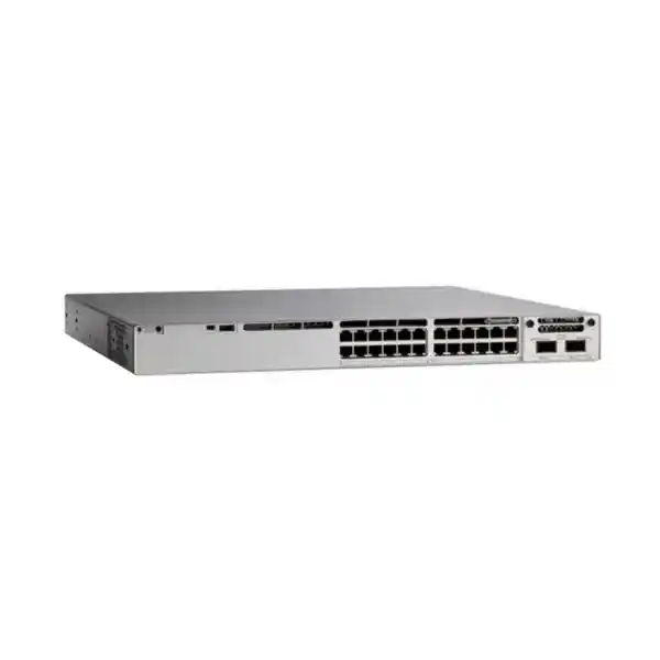
Cisco Catalyst C9300L-24UXG-2Q Network Switch
A compact, high-performance Catalyst 9300L platform for organizations that need multigigabit copper at the access layer, substantial UPOE power, high-bandwidth 40G uplinks, stackable resiliency and Cisco IOS XE operational consistency. The C9300L-24UXG-2Q is particularly well suited to offices, hotels, universities, hospitals, government facilities, retail headquarters and distributed enterprise campuses in Dubai, Abu Dhabi, Sharjah and across the UAE.
8 × multigigabit UPOE
16 × 10/100/1000 Ethernet
2 × 40G QSFP+ fixed uplinks
StackWise-320 support
1100W AC primary power supply
722W listed PoE budget with default PSU
Direct answer: what makes the C9300L-24UXG-2Q different?
The Cisco Catalyst C9300L-24UXG-2Q is a fixed-uplink member of the Catalyst 9300L family designed for access networks where ordinary 1 Gigabit Ethernet is no longer enough for every endpoint. Sixteen front-panel copper ports provide conventional 10/100/1000 Mbps access, while eight multigigabit ports can negotiate 100 Mbps, 1 Gbps, 2.5 Gbps, 5 Gbps or 10 Gbps according to endpoint capability and cabling conditions. Those eight multigigabit interfaces are especially valuable for high-throughput Wi-Fi access points, workstation docks, specialized imaging systems, content creation stations, high-speed edge appliances and other devices that can exceed one gigabit without requiring a fiber run to the desk or ceiling.
The uplink design is another defining feature. Instead of four 10G SFP+ uplinks found on the C9300L-24UXG-4X variant, this model uses two fixed 40G QSFP+ uplinks. For a properly engineered campus, that allows a 24-port access switch to connect upstream with a very high aggregate bandwidth ceiling and fewer physical uplink interfaces. The model also supports StackWise-320, letting compatible Catalyst 9300L switches operate as a resilient stack with a common operational plane and substantial stack bandwidth. This is useful when the design calls for simplified management, cross-stack resiliency and predictable expansion without moving immediately to a chassis architecture.
For UAE buyers, the practical question is not simply whether the switch has enough ports. The better question is whether the mix of copper speeds, UPOE power, uplink capacity, software entitlement, stacking design, transceiver choice and power redundancy matches the building. FourTeck positions the C9300L-24UXG-2Q as an engineered campus component rather than a standalone commodity. That means sizing access-point density, endpoint power requirements, IDF topology, upstream core capacity, optical reach, rack power, heat load and growth headroom before a bill of materials is finalized.
Verified hardware architecture and port map
16 × 1G access ports
Sixteen RJ-45 access interfaces support 10/100/1000 Mbps Ethernet. These ports are appropriate for standard user PCs, printers, VoIP endpoints, cameras, room systems, badge readers and conventional access devices that do not need multigigabit data rates.
8 × multigigabit UPOE
Eight copper interfaces support multigigabit operation at 100 Mbps, 1, 2.5, 5 and 10 Gbps. They also support Cisco UPOE, making them ideal for powered endpoints whose throughput or power profile exceeds ordinary access-layer requirements.
2 × 40G QSFP+ uplinks
Two fixed 40 Gigabit Ethernet uplink interfaces provide high-bandwidth connectivity toward a distribution or core layer. Optics, cabling, breakout strategy and peer-side support must be selected as part of the complete design.
StackWise-320
The C9300L-24UXG-2Q supports StackWise-320, allowing compatible units to be interconnected as a stack. This increases operational simplicity and provides design options for resilient uplinks and distributed access capacity.
The port layout is deliberately asymmetric because enterprise access networks are asymmetric. A typical floor does not need every port to run at 2.5, 5 or 10 Gbps. It needs a targeted pool of faster interfaces for devices that can benefit from them and a larger set of 1G ports for ordinary endpoints. This mixed approach controls cost while still creating a path for Wi-Fi 6, Wi-Fi 6E and other bandwidth-intensive edge deployments. In many UAE offices, eight multigigabit ports align well with access-point counts per IDF, while the remaining sixteen ports serve phones, cameras, desktops and building systems.
Multigigabit Ethernet is most valuable when the entire path is considered. A 5 Gbps or 10 Gbps access point connection is useful only if the upstream switch fabric, uplink, aggregation layer, WLAN design, gateway capacity and application path can carry the additional load. Copper category, pair quality, distance, patch-panel condition and electromagnetic environment also influence achievable rates. Therefore a deployment should include cable qualification rather than assuming every existing horizontal run will automatically support the highest advertised speed.
The two 40G QSFP+ uplinks can substantially reduce the probability that a high-density access switch becomes uplink constrained. They are suitable for direct connection to distribution switches that expose compatible 40G interfaces, and they can also be incorporated into designs using supported breakout or aggregation approaches where appropriate. Optics must be selected for media type, distance, connector standard and peer compatibility. In a new build, the uplink architecture should be designed at the same time as the access layer so that fiber type, strand count, patching and transceiver inventory all line up operationally.
Switching performance, forwarding capacity and practical throughput planning
Cisco lists the C9300L-24UXG-2Q with 352 Gbps switching capacity in standalone operation and 672 Gbps when the stacking architecture is included in the published platform figures. Forwarding performance is listed at 261.90 Mpps in the standalone figure and 500.00 Mpps with stacking. These numbers matter because the model can combine eight access ports capable of 10 Gigabit Ethernet with two 40G uplinks, creating a much higher potential edge throughput profile than a conventional 24-port Gigabit switch.
Raw switching figures, however, should not be treated as a substitute for traffic engineering. Real deployments are shaped by oversubscription, burst patterns, application mix, access-point scheduling, north-south versus east-west flows, VLAN segmentation, policy features and the behavior of the upstream network. A branch office with twenty employees might never approach the switch capacity, while a university lab, media floor, healthcare imaging department or dense wireless environment can create simultaneous multigigabit demand. The correct sizing method starts with endpoints and applications, then evaluates expected concurrent traffic and finally checks uplink and aggregation capacity.
For wireless deployments, consider the aggregate radio capacity of each access point rather than the theoretical maximum of a single client. Modern access points may use multiple radios and wide channels, and the wired uplink must carry management, user traffic, tunneling overhead and service traffic. A 2.5G or 5G wired connection is often chosen to prevent the wired interface from becoming the first bottleneck. In high-performance scenarios, the 10G capability of the multigigabit ports can provide additional headroom, but the access point itself, power requirement and cable plant must support that operating mode.
For wired high-performance endpoints, the same principle applies. A 10G desktop link does not guarantee 10G application throughput. Storage arrays, servers, security controls, WAN circuits, cloud connectivity and application stacks may be slower. The value of the C9300L-24UXG-2Q is that it prevents the access switch from being the obvious limiting factor while giving the architect room to tune the network around actual business demand. In procurement, this is often a better long-term strategy than filling every floor with pure 1G access switches and replacing them prematurely when Wi-Fi or workstation requirements increase.
UPOE power design: budget the watts before ordering
Default power platform
The model is listed with a 1100W AC primary power supply. Cisco publishes 722W of available PoE power with the default power configuration for this specific C9300L-24UXG-2Q variant.
Secondary PSU options
Published platform tables show increased available PoE budget when a compatible secondary power supply is installed, subject to the chassis, port and power architecture limits. Exact PSU selection should be validated against the intended bill of materials.
Endpoint-driven sizing
Do not divide total wattage evenly by port. Build a port-by-port power worksheet using access points, cameras, phones, lighting or IoT devices, then reserve growth and failure-state headroom.
Redundancy objective
A second PSU can be selected for resiliency, additional PoE capacity or both. The design should state what must remain powered after a PSU failure, not merely whether two supplies are present.
Power over Ethernet is one of the most common sources of access-layer design mistakes. It is easy to count ports and forget that powered devices have different consumption profiles. A desk phone may draw relatively little power, while a high-end wireless access point, PTZ camera, collaboration endpoint or specialized IoT gateway can require considerably more. Cisco UPOE extends the power options available on supported interfaces, but the switch still has an overall power budget. The appropriate design process starts with the endpoint datasheets and maps every powered device to a specific port class and expected consumption.
For the C9300L-24UXG-2Q, the published default PoE budget of 722W with the 1100W primary supply gives substantial capacity, but a serious quotation should never use that number in isolation. The network designer should calculate normal operating draw, startup behavior, maximum device requirement and contingency. If eight high-end access points are connected to the multigigabit ports, their combined power demand should be reserved first. Remaining UPOE-capable access interfaces can then be allocated to phones, cameras and other devices based on priority.
Power redundancy also changes the conversation. Some customers want a second power supply only so that the switch survives a PSU failure. Others want the additional supply to increase the available PoE budget under normal conditions. Those are different objectives and may lead to different engineering decisions. The most resilient design asks what happens during a component failure: how many endpoints must stay powered, whether the remaining supply can carry the critical load, whether the UPS can sustain both power supplies, and whether the rack has independent power feeds.
In UAE deployments, thermal and electrical planning is especially important in telecom rooms that may have variable air-conditioning quality or limited UPS capacity. A high-power access switch should not be installed as if it were a low-consumption unmanaged switch. Rack PDUs, circuit loading, UPS runtime, generator transfer behavior, cooling airflow and cable management all affect reliability. FourTeck can incorporate these factors into the quotation and deployment scope through its broader UAE IT services capability rather than treating the switch as an isolated box.
StackWise-320: designing a resilient access stack
StackWise-320 allows compatible Catalyst 9300L switches to be interconnected so that multiple physical devices can be managed as a coordinated stack. The key design benefit is not simply aggregate stack bandwidth. The operational advantage is the ability to build a floor or equipment-room access layer with centralized configuration, predictable member numbering, resilient control-plane behavior and cross-stack uplink possibilities. For organizations with multiple 24-port switches in one IDF, stacking can reduce day-to-day complexity compared with managing each switch as a completely independent device.
A stack should be engineered as a topology, not improvised after the equipment arrives. Stack cables and adapters must be included where required, member positions should be planned, software versions should be aligned, power strategy should be documented and uplinks should be distributed across different stack members when the upstream architecture supports that approach. The physical rack layout also matters because stack cable length and routing can constrain where members are installed. A clean design keeps stack interconnects short, avoids excessive cable stress and preserves service access to power supplies and uplink optics.
The 320 Gbps StackWise figure describes the stack technology class supported by the C9300L. In practical terms, it enables inter-member traffic to traverse the stack rather than being forced through external uplinks. That is useful when endpoints on one member communicate with services or uplinks physically attached to another. Even so, a good architecture distributes traffic and critical dependencies so that a single member does not become an unnecessary choke point. Redundancy is strongest when stack topology, uplink topology and power topology are designed together.
For a two-switch stack, the engineer should decide whether the two 40G uplinks on each member will be used as independent routed links, Layer 2 port-channel members, a cross-stack EtherChannel, or another design supported by the distribution layer and chosen Cisco software features. The answer depends on whether the upstream environment uses Catalyst core switches, Nexus platforms, another vendor, routed access, traditional VLAN trunks or an SD-Access design. There is no universally correct uplink configuration.
Operationally, stack documentation should include member priority, serial-number mapping, rack position, uplink ports, management address, software train, license entitlement, power-supply assignment and recovery procedures. A stack that is physically robust but poorly documented can still cause long outages during maintenance. FourTeck recommends recording these details during commissioning and handing them over with the network diagrams, port schedules and configuration backup so that internal IT teams can maintain the environment confidently.
Cisco IOS XE and enterprise feature planning
The Catalyst 9300 family runs Cisco IOS XE, giving enterprise teams a familiar operational model for switching, routing, segmentation, telemetry, automation and policy integration. The exact software capabilities available to a C9300L-24UXG-2Q depend on the ordered network license tier, subscription entitlement, IOS XE release and feature combination. Cisco ordering commonly distinguishes Network Essentials and Network Advantage product variants, and organizations should align the entitlement with the functions they actually intend to deploy rather than selecting a license solely on initial purchase price.
At the access layer, baseline requirements usually include VLANs, 802.1Q trunking, link aggregation, spanning-tree protections, quality of service, DHCP security controls, authentication integration, monitoring and access-control features. More advanced designs may add richer routing, policy, segmentation, automation or fabric capabilities. The purchasing decision should therefore begin with an architecture worksheet that lists required protocols and integrations. This avoids a common situation where a switch is physically suitable but the purchased software entitlement does not match the intended design.
IOS XE also matters for lifecycle management. Enterprises should maintain an approved software train, track recommended releases, test upgrades, preserve configuration backups and establish a maintenance process that considers stack behavior and upstream redundancy. In a stack, upgrade planning should account for the entire member set rather than treating switches as independent appliances. Change windows should include prechecks for boot variables, available storage, package state, stack health, licensing and compatibility with connected network management systems.
Automation and telemetry can significantly improve the operational value of a Catalyst access network. Structured monitoring can track interface errors, power consumption, temperature, link negotiation, port flaps, authentication status and uplink utilization. Multigigabit ports deserve particular attention because a link that unexpectedly negotiates at 1 Gbps instead of 2.5, 5 or 10 Gbps may indicate cable quality, endpoint configuration or patching limitations. Catching that condition through monitoring is much faster than waiting for a user to report performance problems.
Security configuration is equally important. The switch can participate in an enterprise access-control design, but no feature replaces correct policy. Unused ports should be disabled or placed in a restricted state, trunking should be explicit, management access should be limited, authentication should use secure protocols, and administrative access should be logged. Management traffic should be separated appropriately from user traffic, and device credentials or keys should be handled through the organization’s established secrets and identity processes. The switch becomes secure when the platform features, software maintenance and operational discipline are applied together.
Why multigigabit matters for Wi-Fi 6, Wi-Fi 6E and high-density wireless
A major reason to choose the C9300L-24UXG-2Q is to remove the traditional 1G ceiling between a high-performance wireless access point and the wired network. Modern enterprise wireless can aggregate traffic from many simultaneous clients, multiple radios and high-efficiency modulation schemes. Even when any single client is well below one gigabit, the total access-point traffic can exceed the capacity of a 1G Ethernet uplink. The switch’s eight multigigabit ports give the wireless designer several wired-speed options without requiring fiber to every access-point location.
The correct negotiated rate depends on the access point, cabling and deployment objectives. Many installations use 2.5G or 5G because those speeds provide a meaningful increase over Gigabit Ethernet while fitting within the capabilities of existing or upgraded twisted-pair cabling. Some environments can justify 10G to selected endpoints, particularly where radios, local traffic patterns or future standards are expected to drive higher aggregate throughput. The switch can support these rates, but the design should avoid paying for capability that the endpoint and cable plant cannot use.
Power is closely linked to wireless design. Advanced access points may need more power than legacy 802.3af devices, especially when all radios, USB interfaces or high-performance modes are enabled. UPOE-capable switch ports provide a stronger platform for these endpoint classes, but the overall PoE budget still needs to be calculated. During design, every access point should be recorded with its maximum required power mode and expected wired speed. This creates a clear mapping of which of the eight multigigabit ports are reserved for wireless and how much power the wireless estate consumes.
The uplink then has to carry the combined wireless load. If eight access points are each connected above one gigabit, a 10G uplink can become a constraint under heavy simultaneous usage. The C9300L-24UXG-2Q addresses this concern with two 40G QSFP+ uplinks, allowing substantially more headroom toward the distribution layer. Whether both are active, redundant, bundled or routed depends on topology. This is particularly attractive for campuses where high-density wireless is concentrated in conference floors, classrooms, auditoriums, hospitality areas, healthcare zones or executive offices.
FourTeck can integrate the switch into a broader UAE network modernization project that includes structured cabling validation, WLAN readiness, switching design, security controls and post-installation testing. Organizations evaluating firewall and segmentation upgrades alongside campus switching can also review FourTeck’s Firewall Dubai solutions so that edge, access and perimeter capacity are planned as one system rather than separate purchases.
40G uplink engineering: optics, fiber, breakout and aggregation considerations
The C9300L-24UXG-2Q uses two fixed 40 Gigabit Ethernet QSFP+ uplink interfaces. This is a high-value feature, but it also means that uplink design must be explicit at quotation stage. A 40G port requires the correct transceiver or cabling approach for the distance, fiber type and peer device. The distribution or core switch must expose a compatible interface or a supported breakout architecture. Assuming that any available fiber and any 40G optic will work is a risky procurement shortcut.
First determine the physical path. For an access switch in an IDF connecting to a nearby distribution rack, short-reach multimode optics or a supported direct-attach approach may be appropriate depending on distance and equipment placement. For longer building or campus links, single-mode optics may be required. The installed fiber should be identified by type, connector, strand availability, patching path and tested loss. If the site uses older multimode cabling, the actual distance limit for the chosen optic must be checked rather than inferred from a newer cabling standard.
Second determine the logical topology. Two uplinks provide options for redundancy and load distribution, but the upstream design controls how they are used. A traditional Layer 2 access model may use an aggregated trunk, possibly distributed across redundant upstream switches if the architecture supports multichassis link aggregation. A routed-access design may use independent routed links with dynamic routing. A stack can distribute uplink members across different physical switches for additional resilience. The design should specify failure behavior: what happens if one optic fails, one fiber path fails, one stack member fails or one upstream switch fails.
Third assess oversubscription. The access side includes up to eight 10G multigigabit ports plus sixteen 1G ports. In theory, simultaneous line-rate traffic from all access interfaces can create a large aggregate demand. In practice, user traffic is bursty and many endpoints do not transmit at line rate together. A 40G uplink can therefore provide a strong balance of capacity and cost for a 24-port access switch. Two 40G interfaces add resilience and additional design freedom, particularly where wireless or high-speed endpoints are concentrated.
Finally account for inventory and operations. Optics should be documented by exact part number, wavelength or media standard, interface location and peer device. Spare strategy should reflect how critical the site is. For large UAE campuses, maintaining standardized optic types across many IDFs can simplify support. Mixing several optical standards unnecessarily increases troubleshooting complexity and spare requirements. A well-designed C9300L deployment therefore includes the fiber and transceiver bill of materials as part of the switch order rather than treating them as accessories to solve during installation.
Campus deployment patterns in the UAE
Corporate offices
Use multigigabit ports for high-capacity access points and selected workstation or collaboration devices, while 1G ports serve phones, printers and standard desks. Dual 40G uplinks provide headroom toward a resilient distribution pair.
Hospitality
Hotels and serviced residences can use the platform in IDFs that aggregate dense Wi-Fi, IP phones, cameras and operational systems. UPOE budget planning is critical because multiple powered endpoint classes may share the same access switch.
Education
Classrooms, labs and lecture halls benefit from multigigabit AP connectivity and high-capacity uplinks, particularly when many users synchronize cloud content or stream simultaneously.
Healthcare
Clinical and administrative networks can segment users, medical systems, cameras, voice and wireless while reserving higher-speed ports for imaging, access points or specialized equipment where approved by the application architecture.
Retail headquarters
A 24-port mixed-speed platform is useful for management offices, video, wireless, access control and operational systems where a full 48-port switch would create excess port capacity but 1G-only switching would constrain growth.
Government and regulated sites
The platform can fit structured enterprise designs that require controlled management, segmented access, resilient uplinks and documented lifecycle processes, subject to the organization’s specific security and procurement standards.
UAE network rooms often combine several practical constraints: limited rack depth, mixed-age cabling, central UPS systems, high ambient heat outside conditioned spaces and a requirement to keep business services online during maintenance. The C9300L-24UXG-2Q should therefore be assessed as part of the physical environment. The published chassis height is approximately 4.4 cm, consistent with a 1RU class switch, while depth varies with the installed power-supply configuration. Rack clearance should allow for power cords, airflow and service access.
For greenfield projects, allocate the switch ports before cabling is finalized. Reserve multigigabit ports for known high-speed devices, identify PoE loads, label uplinks and define spare ports. For brownfield projects, survey the existing patch panels and horizontal runs, because a switch upgrade cannot repair degraded copper. Cable certification is especially important when the business expects 5G or 10G copper operation. Existing outlets that perform well at 1G may not meet the channel requirements for higher rates under all conditions.
Organizations with sites outside the UAE can use the same architecture principles across regional branches while adjusting optics, support coverage and procurement logistics. FourTeck supports broader regional sourcing through its Africa technology platform, allowing multi-country projects to standardize the logical design while accounting for local delivery and support conditions.
Segmentation, security and access-control design
An enterprise access switch sits at the point where users and devices first enter the wired network, so security design should begin at the port. The C9300L-24UXG-2Q can participate in a layered access-control architecture that separates user groups, device classes and management functions. The exact feature set depends on software and licensing, but the design principles remain consistent: authenticate where appropriate, limit trust boundaries, reduce unnecessary Layer 2 reach, protect control protocols and monitor abnormal behavior.
VLAN segmentation is the baseline in many networks. Corporate users, voice, cameras, wireless access points, guest services, building management, printers and management traffic should not automatically share the same broadcast domain. VLANs by themselves are not a complete security policy, but they provide a structural foundation for routing, firewall policy and access controls. The switch port schedule should identify the intended VLAN or authentication method for every port, particularly in hospitality and healthcare environments where many unmanaged devices are present.
Port security mechanisms and authentication can further limit unauthorized access. Organizations may integrate wired 802.1X, MAC-based authentication, network access control systems or identity services according to their environment. Implementation should account for devices that cannot perform user-based authentication, such as printers, cameras and embedded systems. Fallback behavior must be deliberate; an authentication failure should not silently place an unknown endpoint into a trusted production segment.
Layer 2 protection also deserves attention. Features that guard against accidental or malicious spanning-tree changes, rogue DHCP behavior and address spoofing can reduce risk when correctly deployed. These controls need careful testing because an aggressive security configuration can disrupt legitimate services if DHCP relay, static addressing, virtualization or specialized endpoints are not understood. A phased rollout with monitoring is generally safer than enabling every protection globally in one change window.
Management access should use secure protocols and restricted source networks. Telnet and other insecure legacy methods should be avoided where possible. Administrative authentication should integrate with the organization’s identity and logging processes, and local emergency credentials should be controlled. Configuration backups, audit logs and change records should be retained so that the state of the switch is recoverable and attributable. For stacks, document changes at the logical stack level as well as the physical member affected.
Finally, remember that access switching and perimeter security are complementary. A firewall cannot compensate for an unsegmented campus, and a well-segmented campus still needs appropriate controls between zones, sites and internet services. Organizations can engage FourTeck through the FourTeck UAE team to coordinate switching, firewalling, wireless, structured cabling and systems integration as a single design effort.
High availability: model failures before they happen
High availability is not achieved by purchasing a stack cable or second power supply alone. It is achieved by identifying failure scenarios and ensuring the network can tolerate the ones that matter to the business. For the C9300L-24UXG-2Q, the main access-layer failure domains include the switch member, stack interconnect, power supply, electrical feed, uplink optic, fiber path, upstream distribution device and software state. Each of these can be addressed differently.
At the switch level, stacking allows multiple physical members to operate together. Endpoint connections can be distributed across members when physical cabling permits, and uplinks can be split across different members so that a single member failure does not necessarily isolate the entire stack. Where critical servers or appliances use dual network interfaces, they can be connected to separate members according to the supported host and network design. User devices with a single Ethernet port cannot be made physically redundant at the switch port, so the business impact of a member outage still depends on which endpoints are attached to it.
At the power level, a second compatible PSU can provide resilience, but the rack power design determines whether that resilience is meaningful. If both PSUs connect to the same overloaded PDU or the same UPS output, many upstream power failures will affect both at once. Critical environments should evaluate independent feeds, UPS capacity, generator support and expected runtime. The power design should also confirm whether the surviving PSU configuration can continue supplying the required PoE load after a failure.
At the uplink level, the two 40G interfaces provide a strong basis for redundant connectivity. The resilient design normally separates physical fiber paths where possible and terminates links on independent upstream infrastructure when the network architecture supports it. Two fibers in the same tray following the same route may protect against an optic failure but not against a cable cut. A design document should distinguish component redundancy from path diversity.
Software resilience requires disciplined lifecycle management. Stack members should run a compatible and approved image, and upgrades should be tested with the relevant feature set. Configuration changes should be peer reviewed for critical sites. Monitoring should alert on stack member state, power-supply status, high temperature, uplink loss, interface errors and persistent PoE faults. The purpose of telemetry is not merely to collect data; it is to shorten the time between degradation and corrective action.
A well-engineered solution therefore defines target availability before hardware is ordered. A normal office floor may accept a brief maintenance outage and use a simple two-member stack. A hospital, trading floor, airport facility or critical operations center may need stronger path diversity, dual power, spare hardware, documented recovery procedures and active support coverage. The same switch can participate in either environment, but the surrounding architecture determines the actual service resilience.
Cabling and physical infrastructure for multigigabit success
A multigigabit switch can only deliver multigigabit performance when the copper channel supports it. Existing structured cabling in UAE buildings varies widely in age, category, installation quality and environmental exposure. Some sites have modern Category 6A channels with documented certification, while others rely on older Cat5e or Cat6 runs installed across multiple fit-out phases. The C9300L-24UXG-2Q can negotiate down to lower rates, but an organization buying it specifically for 2.5G, 5G or 10G should verify the physical layer.
Cable qualification should cover the complete permanent link or channel, not just the patch cord at the switch. Problems may exist in the horizontal cable, patch panel termination, consolidation point, faceplate or patch lead. Poor pair termination, excessive untwist, damaged cable, marginal insertion loss or alien crosstalk can limit higher-speed operation. A port that links at 1G may still fail to sustain a higher multigigabit rate reliably. Testing before migration reduces surprises during the change window.
Power delivery adds another variable because higher-powered endpoints draw current through the same copper pairs. Cable bundle size, conductor gauge, ambient temperature and pathway design influence thermal behavior. In dense PoE installations, especially above ceilings or in large bundles, cabling standards and manufacturer guidance should be followed. The switch’s UPOE capability is valuable, but it should be paired with appropriately rated cabling and installation practices.
For 40G uplinks, fiber infrastructure should be audited separately. Identify whether the path is multimode or single-mode, the fiber generation, connector format, available strands, patch-panel type and measured distance. Confirm that the selected QSFP+ optics support that media and reach. If the distribution layer is being upgraded at the same time, standardize optic families where practical. Standardization lowers spare inventory and simplifies troubleshooting when several IDFs use the same architecture.
Rack design also affects cabling quality. Twenty-four copper connections plus uplinks, stack cables and power cords can become difficult to service if horizontal and vertical cable managers are absent. Keep copper bend radius within specification, avoid blocking fans or power-supply airflow and label both ends of every connection. Multigigabit ports should be clearly identified so that high-speed endpoints are not accidentally moved to ordinary 1G interfaces during future patching.
A commissioning record should capture port number, patch-panel port, outlet ID, endpoint, negotiated speed, VLAN or authentication role, PoE status and test result. This turns the switch configuration into an operational asset rather than a black box. When a user later reports slow wireless service, the support team can immediately see whether the access point is on the intended multigigabit port and whether the link negotiated at the expected rate.
Sizing methodology: how many C9300L-24UXG-2Q switches does your site need?
Switch quantity should be calculated from more than total outlet count. A useful sizing worksheet separates endpoint ports, high-speed ports, PoE requirements, uplink bandwidth, redundancy and growth. Start by listing every active endpoint expected in the IDF: access points, desktops, phones, printers, cameras, meeting-room systems, access-control panels, IoT gateways and any local servers or appliances. Then identify which endpoints need multigigabit speed and which require PoE.
The eight multigigabit ports are often the first limiting resource. If an IDF requires ten or twelve multigigabit access-point connections, a single C9300L-24UXG-2Q cannot satisfy the design even if many of the sixteen 1G ports remain unused. In that case, the choice may be to deploy two 24-port units, select a different 48-port model with more multigigabit interfaces, or redesign AP distribution between closets. Port count alone would miss this constraint.
Next calculate PoE. Record maximum or design power for each powered endpoint and compare the total with the available budget under the planned PSU configuration. Add sensible headroom for endpoint replacement and future additions. If the required power exceeds the default budget, determine whether a second supply or another switch is the more appropriate solution. Redundancy requirements may also drive a second supply even when the wattage fits comfortably within the default budget.
Then evaluate uplinks. A small office with several multigigabit APs may still be well served by one 40G uplink and one redundant 40G link. A high-density floor may need both links active in an architecture that can use the aggregate capacity. The distribution layer must have sufficient 40G port density. If it does not, the cost of upgrading the core or using a different uplink approach must be included in the project decision.
Growth reserve is the final part of the calculation. Filling all twenty-four ports on day one creates an operational problem because any new device requires repatching or another switch. A common engineering approach is to reserve a percentage of ports and power budget for reasonable growth, but the appropriate percentage depends on the building and business plan. A stable industrial site may need little spare capacity, while a rapidly expanding office or education campus needs more.
For a complete quotation, FourTeck can translate these inputs into a bill of materials that includes switch quantity, licensing, stacking components, power supplies, QSFP+ optics, patching and implementation. This project approach helps prevent the hidden accessory gaps that often appear when buyers compare only the base switch price.
Licensing and ordering: Essentials, Advantage and lifecycle planning
Cisco Catalyst switching orders commonly include a hardware SKU variant tied to a network license tier, such as Network Essentials or Network Advantage. For this model, ordering identifiers may include C9300L-24UXG-2Q-E and C9300L-24UXG-2Q-A variants. The physical switch platform remains centered on the same port architecture, but the software entitlement differs. Buyers should therefore specify both the hardware need and the feature requirement when requesting a quotation.
Network Essentials generally addresses foundational enterprise access use cases, while Network Advantage is intended for organizations requiring a broader feature set. Exact feature availability can vary by Cisco IOS XE release and licensing program, so the correct procurement method is to map required functions to the current Cisco licensing matrix at the time of order. Features involving advanced routing, segmentation, automation, fabric integration or policy services should be checked specifically rather than assumed.
Subscription entitlements and management integrations should also be planned. Cisco has evolved its software packaging over time, and organizations operating long equipment lifecycles should document what licenses are perpetual, subscription-based or term-bound under the commercial program used for the purchase. Renewal ownership should be assigned internally so that the switch does not reach a renewal date without budget or operational awareness.
Support coverage is a separate decision from software features. Mission-critical sites may require a support level with faster replacement or technical response, while noncritical branches may accept a different service objective. The appropriate choice depends on spare strategy, business impact, local stock and the organization’s own support capabilities. A customer that keeps a cold spare on-site may have different requirements from one that relies entirely on vendor replacement.
Software lifecycle also affects hardware planning. Before standardizing on a release, review compatibility with network management platforms, authentication systems, monitoring tools and any automation workflows. A new switch should not be introduced with an arbitrary factory software version if the rest of the campus is standardized elsewhere. Upgrade or downgrade planning should be included in commissioning so that all stack members and sites converge on an approved image.
FourTeck’s quotation process can separate hardware, license entitlement, support, power options and optics so procurement teams can see what each component contributes. This is particularly useful when comparing an Essentials-based build with an Advantage-based build or evaluating whether a second power supply is required for redundancy. Clear line-item visibility reduces the risk of receiving a switch that is physically correct but commercially or operationally incomplete.
Operations, monitoring and troubleshooting framework
A production access switch should be commissioned with a monitoring baseline. At minimum, operators should track interface state, negotiated speed, duplex, errors, discards, uplink utilization, stack member health, temperature, fan status, power-supply status and PoE consumption. The multigigabit interfaces make negotiated speed especially important. If a 5G-capable access point unexpectedly falls back to 1G, the monitoring system should reveal that condition before users experience sustained congestion.
Interface error counters are another useful diagnostic. CRC errors, input errors or frequent link flaps can point to copper or fiber problems, endpoint behavior or transceiver issues. Baselines help distinguish a one-time installation event from an ongoing fault. For fiber uplinks, optical diagnostics should be captured when supported so that receive and transmit levels can be compared over time. A gradual degradation may indicate contamination, connector damage or a developing fiber problem.
PoE telemetry can identify endpoints drawing unexpectedly high or low power, ports denied power and capacity approaching the configured budget. In an environment with many access points or cameras, these alerts are operationally important. A powered endpoint that loses PoE may look like a network outage even when the data plane of the switch is healthy. Support procedures should therefore check power state as well as link state.
Configuration backups should be automatic and tested. A backup is valuable only if the organization can restore it and understands any dependencies such as certificates, licensing or external authentication. For stacked switches, the backup should be associated with the stack identity, and physical member serial numbers should be recorded separately. Replacement procedures should explain how a failed member is introduced, how the intended member number is preserved and how the replacement reaches the approved software state.
Troubleshooting should follow layers. Verify power and physical link first, then negotiated speed, VLAN or routing state, authentication, policy and finally application behavior. For a multigigabit endpoint, confirm cable qualification and endpoint NIC settings before changing switch features. For a 40G uplink issue, verify optic type, fiber polarity, light levels, peer configuration and aggregation state. A structured method reduces disruptive trial-and-error changes.
Organizations that prefer managed assistance can combine Cisco switching procurement with deployment and ongoing support from FourTeck. This can include rack installation, configuration, migration, testing, documentation and coordination with firewall, wireless and server teams. The result is a switch implementation that is integrated into the broader IT operating model rather than delivered as unconfigured hardware.
Migration strategy from legacy Catalyst or third-party access switches
Replacing an access switch is a service migration, not just a rack activity. The safest process begins by collecting the existing configuration and port usage. Export the current switch configuration, MAC address table, VLAN assignment, trunks, port-channels, voice settings, authentication policies, PoE status and interface descriptions. Compare that information with the physical patching and business owner input. Old switch configurations often contain abandoned ports or legacy settings that should not be copied blindly.
Next build the target configuration for the C9300L-24UXG-2Q. Assign standard 1G endpoints to the sixteen conventional interfaces and reserve the eight multigigabit ports for devices that need them. If the migration includes upgraded access points, coordinate the AP replacement with switch port and PoE planning. Define uplink ports, optic types and redundancy before the cutover. If stacking is used, build and test the stack before production patching begins.
Software version alignment should happen before the maintenance window where possible. Confirm the intended IOS XE release, license state, stack compatibility and required configuration syntax. Load the approved image, verify boot settings and test management access. If the organization uses TACACS+, RADIUS, SNMP, telemetry, syslog or configuration-management platforms, validate that the new switch can reach those services in a staging context or through a controlled commissioning sequence.
During cutover, move ports in a documented order. Critical services should be identified first, and each group of endpoints should be tested after repatching. Wireless access points may take time to boot and rejoin controllers or cloud management systems, so allow for that behavior. Phones may need to renew DHCP and register. Cameras may require validation from the video management platform. A port showing link is not sufficient evidence that the service is operational.
Post-cutover validation should compare expected and actual state. Check stack health, uplinks, spanning-tree or routing status, VLANs, authentication, PoE budget, interface errors and negotiated multigigabit speeds. Monitor uplink utilization during a normal busy period if possible. Save the final configuration and update network diagrams, rack elevations and port schedules. The old switch should not be removed from the recovery plan until the new environment has passed the agreed validation criteria.
For multi-floor or multi-site projects, migrate in phases. A pilot IDF can expose cabling, licensing, optic or configuration assumptions before dozens of switches are changed. Once the design is proven, standard templates and checklists reduce variation. This approach is particularly useful for hotels, campuses and distributed UAE enterprises where a repeatable method is more important than completing every location in one large maintenance event.
Procurement considerations for Dubai, Abu Dhabi and the wider UAE
Enterprise switching procurement should begin with an exact configuration rather than a generic request for a Catalyst 9300. The C9300 family includes fixed and modular uplink models, different port counts, different PoE classes and multiple multigigabit combinations. The C9300L-24UXG-2Q specifically matters when the requirement is twenty-four copper access ports, eight of them multigigabit UPOE, plus two fixed 40G QSFP+ uplinks. A small change in suffix can materially change the hardware.
A complete UAE request for quotation should state the license tier, quantity, stack requirement, secondary power supply requirement, optics, fiber distance and support target. If the buyer provides only the base model, the supplier may quote a hardware unit that lacks necessary accessories. Stack components, transceivers and power supplies should be listed explicitly. For replacement projects, include existing upstream switch models so uplink compatibility can be checked before shipment.
Lead time and project schedule should be coordinated. Network switches are often one dependency in a larger fit-out involving racks, UPS systems, cabling, wireless access points and security appliances. Installing the switch before the fiber path or electrical capacity is ready does not advance the project. Conversely, waiting until the final week to order optics or licenses can delay commissioning. A bill of materials with dependency tracking is more reliable than separate ad-hoc purchases.
Warranty and support documentation should be associated with the serial numbers at handover. Procurement teams should retain purchase records, license entitlement information and support contract details in the asset system. IT teams should know the escalation path and whether replacement hardware is held locally. This matters more for critical environments than marginal differences in purchase price.
For organizations operating across the Emirates, standardization can reduce operational cost. Using the same C9300L model, IOS XE release, optic family, configuration template and monitoring profile across similar IDFs makes troubleshooting faster and spare planning easier. Standardization should still respect site differences: a small branch may not need dual power, while a headquarters floor may require full redundancy. The platform can remain common even when resilience options differ.
FourTeck can provide product sourcing, design assistance and implementation coordination for Cisco switching projects in the UAE. Customers can engage the broader FourTeck UAE portfolio for related networking requirements while keeping the C9300L-24UXG-2Q quotation aligned to the actual building and support model.
Technical specification summary
| Specification | Cisco Catalyst C9300L-24UXG-2Q |
|---|---|
| Access ports | 24 copper ports total |
| Standard copper | 16 × 10/100/1000 Mbps Ethernet |
| Multigigabit copper | 8 × 100M / 1G / 2.5G / 5G / 10G |
| Power over Ethernet | Cisco UPOE supported on the 24-port access platform |
| Fixed uplinks | 2 × 40 Gigabit Ethernet QSFP+ |
| Stacking | StackWise-320 |
| Primary PSU | 1100W AC |
| Published available PoE power | 722W with default 1100W primary power supply |
| Switching capacity | 352 Gbps standalone; published stacked figure 672 Gbps |
| Forwarding rate | 261.90 Mpps standalone; published stacked figure 500.00 Mpps |
| Operating system | Cisco IOS XE |
| License variants | Network Essentials and Network Advantage ordering variants; confirm current entitlement for required features |
| Form factor | Rack-mount enterprise access switch, approximately 1RU class |
| Best-fit role | High-performance enterprise access for Wi-Fi, voice, video, users and powered edge devices |
Specification planning note: exact software entitlements, supported optics, power-supply combinations and feature behavior should be validated against the active Cisco documentation and the bill of materials used for the order.
Decision recap: when this model is the right choice
Choose it when
You need a 24-port enterprise access switch with a targeted set of multigigabit copper ports, substantial UPOE capability, two 40G uplinks, Cisco IOS XE and StackWise-320. It is especially attractive where several high-performance access points share an IDF with ordinary 1G endpoints.
Consider another model when
You need more than eight multigigabit access ports, more than twenty-four copper ports, modular uplink flexibility, a different stack architecture or a different PoE density. The best Catalyst 9300-family choice depends on the endpoint mix, not on model hierarchy alone.
Confirm before purchase
License tier, IOS XE feature requirements, second PSU requirement, stack components, QSFP+ optic type, fiber path, peer-side 40G support, PoE budget, multigigabit cabling and support coverage should all be confirmed in the quotation.
Plan for lifecycle
Standardize software, monitor negotiated speeds and power, retain configuration backups, document serial numbers and optics, and maintain a tested upgrade process. The operational plan is as important as the hardware specification.
The C9300L-24UXG-2Q is not simply a faster 24-port switch. Its value comes from matching different edge requirements in one access platform. Ordinary devices can remain on cost-efficient 1G interfaces, while demanding endpoints use multigigabit copper and UPOE. The dual 40G uplinks prevent the access layer from being designed around a low upstream ceiling, and StackWise-320 provides a practical path to multi-switch resilience. For many UAE enterprises, that combination creates a balanced transition from legacy Gigabit access toward higher-density wireless and more demanding edge applications without replacing every copper connection with fiber.
Quotation input checklist for Cisco C9300L-24UXG-2Q UAE
A precise quotation is faster when the technical inputs are clear. Use the following checklist when requesting pricing or design assistance. If an item is unknown, FourTeck can help determine it during the presales process.
Number of switches, city, building count, IDF count and whether equipment is for a new build, expansion or replacement.
Network Essentials or Network Advantage requirement, plus any current Cisco subscription or management entitlement that must be aligned.
Count and type of devices needing 2.5G, 5G or 10G, including wireless access-point model numbers where available.
Powered endpoint count, device models, maximum power demand and whether all devices must remain powered during a PSU failure.
Distribution or core switch model, required number of 40G links, fiber type, distance and whether redundant physical paths are available.
Number of members per stack, desired rack positions, stack cable requirements and whether uplinks should be distributed across members.
Whether a secondary PSU is required, rack PDU type, UPS availability and any dual-feed requirement for critical operations.
Hardware supply only, staging, configuration, migration, cabling test, onsite installation, documentation, monitoring integration or post-cutover support.
Final consultation panel: build the switch into the network, not beside it
The strongest deployment of the Cisco Catalyst C9300L-24UXG-2Q starts with the application and endpoint requirements, then works backward to ports, power, cabling, uplinks, software and resilience. That process prevents three common problems: buying too few multigigabit ports, underestimating PoE demand and discovering after installation that the upstream network cannot use the 40G uplinks as intended.
For a typical UAE office, the model can serve as a compact high-performance IDF switch with eight multigigabit access points or other fast endpoints, sixteen conventional Gigabit devices and a resilient 40G path to distribution. For a hotel, campus or healthcare environment, multiple units can be stacked and standardized across floors. For a critical site, the design can add secondary power, redundant fiber paths, support coverage, monitoring and documented recovery procedures.
FourTeck can prepare the bill of materials around the exact C9300L-24UXG-2Q variant and include optics, stacking, licensing, power, migration and documentation requirements. Where the switch is part of a larger refresh, the same project can coordinate wireless, firewall, server connectivity and structured cabling so that the access layer is sized against real upstream and endpoint capacity rather than treated as an isolated purchase.
For broader networking, infrastructure and deployment discussions, visit FourTeck IT Services UAE or the main FourTeck UAE site. The goal is a complete access-layer solution in which switching capacity, endpoint power, uplink bandwidth, cabling and operational support all align with the business requirement.

Reviews
There are no reviews yet.