
Enterprise Campus Access • UAE
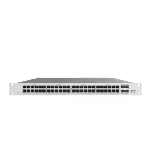
Cisco Catalyst C9300L-48UXG-2Q Network Switch
The Cisco Catalyst C9300L-48UXG-2Q is a 48-port fixed-uplink enterprise access switch designed for networks that have outgrown simple 1 Gigabit edge connectivity. It combines 36 traditional 10M/100M/1G copper interfaces with 12 multigigabit copper interfaces capable of 100M, 1G, 2.5G, 5G and 10G, Cisco UPOE on access ports, two integrated 40 Gigabit QSFP+ uplinks and StackWise-320. For UAE organizations, this combination is especially valuable where high-performance wireless access points, IP phones, surveillance endpoints, collaboration devices, building systems and user workstations must share a resilient access-layer architecture without requiring a separate switch family for every endpoint class.
12× up to 10G mGig
2× 40G QSFP+
Cisco UPOE
StackWise-320
Direct answer
Choose the C9300L-48UXG-2Q when a 48-port access closet needs multigigabit endpoint capacity, strong PoE delivery, dual 40G upstream bandwidth and hardware stacking without the cost or operational complexity of a modular chassis.
What the C9300L-48UXG-2Q is built to solve
Modern access networks are no longer limited by the number of RJ-45 sockets in a wiring closet. The real design challenge is balancing endpoint speed, power demand, uplink oversubscription, segmentation, resiliency and operational visibility. A floor may contain ordinary 1G desktops beside multigigabit wireless access points, PoE-powered cameras, room systems, VoIP phones, badge readers and IoT gateways. If every endpoint is forced onto a uniform 1G design, the switch can become the limiting element. If every port is built for 10G, the project can become unnecessarily expensive. The C9300L-48UXG-2Q takes a balanced approach: high-density 1G where 1G is appropriate, twelve multigigabit ports for devices that genuinely need more, and two 40G fixed uplinks to keep aggregate traffic moving toward distribution, core or services.
The switch belongs to Cisco’s Catalyst 9300 family, a platform aimed at enterprise campus access. It runs Cisco IOS XE and uses Cisco UADP 2.0 programmable silicon. That matters because the product is not merely an unmanaged concentration point. It is intended to participate in enterprise policy, telemetry, security and automation workflows. Network teams can build conventional VLAN and routed-access designs, use rich quality-of-service policies, collect flow visibility, integrate authentication and identity controls, and operate the access layer as part of a larger Cisco campus architecture.
For procurement teams in Dubai, Abu Dhabi, Sharjah and other UAE locations, the model is best treated as an engineered component rather than a commodity switch. The correct bill of materials depends on software tier, stacking requirements, secondary power supply strategy, 40G optics or DAC choices, multigigabit copper cabling quality, total PoE load and support coverage. FourTeck can align the switch with the rest of the LAN, firewall, server and wireless design instead of treating each line item in isolation.
Core specifications at a glance
48-port access density with a practical multigigabit mix
The most important design feature of the C9300L-48UXG-2Q is the way its front-panel ports are divided. Thirty-six interfaces are conventional copper access ports for 10 Mbps, 100 Mbps and 1 Gigabit Ethernet. Twelve interfaces are multigigabit and can negotiate 100 Mbps, 1 Gbps, 2.5 Gbps, 5 Gbps or 10 Gbps. This mixed port architecture is useful because real access layers are heterogeneous. A finance workstation, printer, desk phone or building controller may never need more than 1G, while a contemporary enterprise wireless access point can exceed 1G aggregate throughput and benefit from 2.5G or 5G. High-performance local devices can use 10G over copper when distance and cabling are appropriate.
The multigigabit ports are particularly valuable during wireless upgrades. Many organizations replace access points more frequently than horizontal cabling. Multigigabit Ethernet allows additional bandwidth over suitable installed copper without automatically requiring fiber to every access point. The exact achievable rate depends on cable category, length, installation quality, patching and electromagnetic environment. For 10GBASE-T operation, Cisco specifically recommends Category 6A or Category 7 cabling on this platform. A professional survey should therefore treat the switch and the structured-cabling plant as one system, especially in older buildings where cable quality is mixed.
The twelve-port mGig allocation also helps control cost. Rather than paying for 48 full 10GBASE-T interfaces when only a subset of endpoints require multigigabit service, the network designer can reserve the high-speed ports for access points, media workstations, edge servers, high-resolution surveillance aggregation or other demanding devices. The remaining 36 ports continue to provide normal enterprise edge connectivity. This makes the model suitable for floors where high-speed devices are concentrated but not universal.
Two 40G QSFP+ uplinks: why the -2Q variant matters
The “2Q” suffix identifies two fixed 40 Gigabit Ethernet QSFP+ uplink interfaces. This distinguishes the model from the C9300L-48UXG-4X, which uses four fixed 10G/1G SFP+ uplinks. The correct choice is not simply “more ports versus fewer ports.” It depends on the upstream topology. Two 40G links can provide substantial aggregate capacity to a distribution pair, collapsed core, aggregation switch or local high-speed service block. They are especially attractive when the access switch hosts multiple multigigabit endpoints and a 10G uplink pair would create a comparatively narrow exit path.
A common enterprise design uses one 40G uplink toward each member of a redundant distribution pair, subject to the selected architecture and supported multi-chassis or routed design. Another approach bundles uplinks where the upstream environment and link-aggregation design permit. The point is to engineer failure domains and bandwidth together. If the switch is populated with many 2.5G, 5G or 10G clients, the uplinks should be sized around expected concurrent traffic, not around the theoretical sum of every access-port line rate. Oversubscription is normal in campus networks, but it should be deliberate rather than accidental.
QSFP+ also affects optics and cabling procurement. Short-range multimode optics, long-range single-mode optics, direct-attach copper assemblies and active optical options serve different distances and rack layouts. Transceiver compatibility, fiber type, connector plan, patch-panel budget and upstream port capabilities must all be validated before ordering. Where the upstream switch only provides 10G SFP+ interfaces, the -4X variant can be operationally simpler. Where native 40G is available, the -2Q version offers a strong high-capacity uplink profile.
Switching capacity and forwarding performance
Cisco publishes a standalone switching capacity of 472 Gbps and forwarding performance of 351.19 million packets per second for the C9300L-48UXG-2Q. When stack bandwidth is included, the corresponding published figures rise to 792 Gbps switching capacity and 589.28 Mpps. These values help demonstrate that the model is engineered for a demanding enterprise edge rather than for light small-office traffic.
Capacity figures should still be interpreted correctly. Switching bandwidth is only one part of a design. Real applications generate a mix of frame sizes, east-west and north-south traffic, multicast, control-plane activity, security policy, QoS treatment and bursts. The advantage of a campus-class platform is that forwarding features are integrated into the switching architecture and backed by hardware resources. Design validation should examine the expected route scale, MAC table requirements, multicast behavior, ACL complexity, NetFlow usage, segmentation model and uplink oversubscription in addition to raw Gbps.
For most access-layer projects, the limiting factor is usually not the published packet-forwarding rate. More commonly, bottlenecks arise from undersized uplinks, poor wireless backhaul planning, legacy cabling, exhausted PoE budgets, incorrect QoS, spanning-tree design problems or a mismatch between endpoint density and upstream architecture. The C9300L-48UXG-2Q gives the network engineer enough platform headroom to focus on those architectural issues.
Cisco UPOE and realistic PoE budgeting
Every access-switch project should calculate power before the purchase order is finalized. The C9300L-48UXG-2Q supports Cisco UPOE and is designed for powered devices that can exceed traditional 15.4 W PoE requirements. Cisco’s current data sheet identifies a 675 W available PoE budget with the default PWR-C1-1100WAC-P power supply. Additional power-supply combinations can increase available PoE capacity: Cisco publishes 1025 W with an added 350 W secondary supply, 1390 W with a 715 W secondary supply and up to 1775 W with a 1100 W secondary supply for this model.
Those values should not be confused with the maximum wattage of every individual port. A switch may support higher per-port power while still having a finite chassis power budget shared across all powered endpoints. The correct sizing method is to build a port-by-port load sheet. List each access point, IP phone, camera, display, video endpoint, thin client, IoT gateway and any future device. Record its negotiated or maximum PoE class, apply a prudent design margin, and calculate the total expected draw. Then decide whether a second power supply is needed for capacity, redundancy or both.
For wireless projects, avoid using access-point marketing power values without checking the exact radio configuration. Some APs reduce radio, USB, IoT or spatial-stream capability when supplied below their preferred power level. Similarly, pan-tilt-zoom cameras and video endpoints can have transient peaks. A conservative PoE model protects the network from brownout-style behavior where devices reboot or disable features under peak load.
Power redundancy also needs explicit thought. The chassis accepts two power supplies and supports redundant load-sharing operation. However, Catalyst 9300L switches do not support StackPower, so power cannot be pooled between C9300L stack members the way it can be in certain other Catalyst 9300 models. Each switch must therefore have its own properly engineered PSU strategy. This detail is important when specifying a resilient stack for a critical floor or facility.
StackWise-320 for resilient access-layer operation
The C9300L-48UXG-2Q supports Cisco StackWise-320. With the required stack hardware, multiple physical switches can operate as a coordinated logical system. Stacking simplifies many operational tasks because administrators can manage a group through a unified control and configuration context rather than treating every access switch as an isolated device. It also enables cross-stack design options that can improve link resiliency and simplify downstream or upstream attachment patterns.
A stack should be designed, not merely cabled. Member placement, stack-ring cabling, switch priorities, software consistency, power redundancy and uplink distribution all affect failure behavior. In a two-member access stack, for example, uplinks can be physically distributed across members so the failure of a single switch does not remove every upstream connection. Critical downstream systems can also use redundant attachment where their network interfaces and protocols support it.
The optional stack kit needs to be included in procurement; it is not something to assume is automatically present with every base switch order. Cable length should match rack layout, particularly in multi-switch vertical arrangements. The engineering team should also reserve rack space and power feeds for the final member count rather than only the first-day population.
For very large deployments, stacking is not a substitute for distribution-layer architecture. Access stacks create operational and failure domains that should remain manageable. Floor-by-floor or zone-by-zone boundaries are often preferable to creating oversized stacks simply because the platform can stack. The correct boundary depends on users, cabling closets, uplink topology, maintenance windows and service criticality.
Hardware resilience, power supplies and serviceability
The switch is a 1RU fixed-access platform with field-replaceable power-supply capability. Cisco lists a chassis height of approximately 4.4 cm and width of 44.5 cm. With the default power-supply configuration, the switch depth is approximately 40.9 cm; deeper power-supply options can extend the installed depth to approximately 48.8 cm. The published weight for the C9300L-48UXG-2Q with its default power supply is approximately 7.65 kg. These physical numbers matter in compact racks, wall cabinets and older telecom rooms where usable depth can be more restrictive than rack-unit count.
Cisco’s architecture for the Catalyst 9300 family includes redundant variable-speed fans, console and management interfaces, USB connectivity, status indication and platform inventory capabilities. Proper front-to-back airflow should be preserved. Blanking, cable management and power-cord routing must not obstruct air paths. UAE installations should pay particular attention to cooling resilience because telecom rooms can experience elevated temperatures during HVAC faults or building-maintenance events.
Cisco specifies an operating environment of approximately -5°C to 45°C for the switch, with a cold-start minimum of 0°C, relative humidity of 5% to 90% non-condensing and operating altitude up to 3000 m. Those values are equipment limits, not targets for room design. Enterprise network rooms should be maintained well inside the allowed envelope to improve long-term reliability and preserve margin during cooling incidents.
Where twelve multigigabit ports make the biggest difference
High-density Wi-Fi
Wireless APs with 2.5G or 5G Ethernet can use the mGig ports while UPOE supplies power. This avoids forcing high-capacity radios through a 1G wired bottleneck and can extend the usable life of structured cabling.
Media and engineering desks
Selected workstations that move large design files, images or datasets can use 5G or 10G copper while ordinary users remain on 1G, controlling cost without sacrificing performance where it matters.
Edge compute and appliances
Local appliances, small servers or service nodes can use higher-speed copper attachment when a fiber NIC is not desirable, while the dual 40G uplinks preserve upstream headroom.
Advanced surveillance
Conventional cameras generally fit on 1G, but video aggregation, analytics appliances or specialized high-bandwidth endpoints can be placed on mGig ports without changing the switch family.
Wi-Fi 6, Wi-Fi 6E and Wi-Fi 7 access-layer planning
Wireless is one of the strongest reasons to deploy this switch. Modern enterprise APs can generate aggregate wireless throughput above 1 Gbps, especially when multiple radios, wide channels and many clients are active. A 2.5G or 5G Ethernet backhaul lets the wired side keep pace without the complexity of running fiber and separate power to each ceiling location. The twelve multigigabit interfaces on the C9300L-48UXG-2Q can therefore be allocated to the highest-capacity APs while the remaining ports serve wired clients and lower-bandwidth devices.
The design still needs power validation. Wi-Fi 6E and Wi-Fi 7 AP families vary widely in PoE requirements. Some products operate fully within 30 W, some prefer 60 W, and some high-end models can request more. The C9300L-48UXG-2Q is a Cisco UPOE platform designed around up-to-60 W access-port operation, so the exact AP data sheet must be checked before assuming full functionality. If an AP requires 90 W for all features, another switch model may be more appropriate.
Cabling certification is equally important. Multigigabit technology is tolerant of several legacy cable environments, but actual performance depends on channel quality. For 10GBASE-T, Category 6A is the sensible enterprise baseline. Cable bundles carrying substantial PoE should also be reviewed for thermal performance, conductor gauge and local installation standards. An access switch upgrade can expose hidden cabling weaknesses, so testing representative links before full rollout reduces deployment risk.
Campus security and segmentation
Access switching is the first enforcement point for many enterprise security policies. The Catalyst 9300 platform supports identity-aware and policy-based designs through features such as 802.1X, MAC Authentication Bypass, downloadable or local access controls, VLAN assignment, Cisco TrustSec Security Group Tags, DHCP snooping, Dynamic ARP Inspection, IP Source Guard and control-plane protection. Exact availability depends on the selected software package and IOS XE release, so the license choice should be tied to the security architecture rather than chosen only on price.
In a conventional campus, the switch can place users, phones, printers, cameras, access points and facilities devices into dedicated VLANs with ACL boundaries. In more advanced deployments, identity platforms such as Cisco Identity Services Engine can make policy decisions based on user, device, posture and location. TrustSec can reduce dependence on large static ACL matrices by carrying group context through the network. This is particularly useful in buildings where the physical cabling topology does not neatly map to security zones.
Segmentation should be aligned with the firewall design. East-west access policy, north-south application policy and internet security do not need to be implemented at the same place. FourTeck can align Catalyst access-layer controls with perimeter and internal firewall policy through its Firewall Dubai solutions, helping avoid contradictory rule sets or unnecessary traffic hairpinning.
Security also includes operational hygiene. AAA, role-based administrative access, secure management protocols, logging, NTP, configuration versioning, image integrity and controlled software upgrades are just as important as packet filters. A well-designed Catalyst deployment treats the switch as part of the enterprise security control plane, not simply as cabling infrastructure.
Cisco IOS XE: operational consistency and programmability
Cisco IOS XE gives the C9300L-48UXG-2Q a mature enterprise operating model. Engineers can use familiar command-line workflows while also adopting APIs, structured telemetry and controller-based automation. This matters in organizations where hundreds of access switches must be configured consistently. Manual configuration can work for a handful of closets, but at scale it becomes difficult to guarantee that VLANs, QoS, AAA, SNMP, telemetry, spanning tree and security controls are identical everywhere.
IOS XE supports model-driven programmability using mechanisms such as NETCONF, RESTCONF and YANG, depending on software release and configuration. These interfaces enable infrastructure teams to integrate switching into automation pipelines. Instead of logging into every switch, a team can validate intended state, push repeatable templates and collect structured operational data. This reduces configuration drift and makes audits easier.
Software lifecycle management should be planned alongside hardware. Cisco publishes recommended IOS XE releases, security advisories and release notes. Before an upgrade, operators should validate feature dependencies, stack behavior, boot variables, package mode, transceiver compatibility and any controller requirements. The right long-term approach is to standardize on a tested software train and maintenance process rather than allowing each access switch to drift onto a different version.
Automation, telemetry and Cisco Catalyst Center integration
The Catalyst 9300 family is designed to work within Cisco’s broader campus-management ecosystem. Cisco Catalyst Center can provide inventory, software-image management, assurance, configuration automation and fabric workflows, depending on licenses and deployment architecture. For operations teams, the value is not simply a central dashboard. The more important benefit is consistent intent: access ports, network services and policy can be deployed through repeatable workflows while assurance data helps correlate user experience with network events.
Streaming telemetry and flow visibility are particularly useful in multigigabit access environments because interface counters alone may not explain intermittent congestion. Telemetry can expose queue drops, errors, client movement, environmental conditions and protocol state. Flexible NetFlow can provide application and conversation visibility, subject to platform scale and configuration. Combined with centralized logs and monitoring, these capabilities shorten troubleshooting cycles.
For customers without Catalyst Center, the switch can still operate as a conventional IOS XE enterprise switch using CLI, SNMP, syslog and automation tooling. Controller adoption can therefore be staged. The procurement decision should separate what the hardware can do from which management model the organization is ready to operate.
Quality of Service for voice, video and real-time applications
High interface speed does not eliminate the need for QoS. Congestion still occurs at points where multiple flows converge, where a fast access port sends toward a slower path, or where bursts compete for queue resources. The UADP 2.0 architecture provides hardware QoS capabilities including classification, marking, policing, queueing and weighted congestion management. Cisco documents eight egress queues per port on the platform family, giving engineers the tools to separate critical real-time traffic from bulk data.
A typical enterprise policy trusts markings only from known devices or authenticated voice endpoints, remarks untrusted traffic, protects network-control protocols and allocates priority treatment to voice. Video conferencing often needs assured bandwidth but should not be allowed to starve every other class. Backup, software distribution and large file transfers can be placed in lower-priority classes. The exact policy should reflect applications, WAN design and upstream treatment; copying an old QoS template without validating current traffic frequently causes unexpected results.
QoS is also relevant to wireless. Access points tunnel or bridge traffic from many users through one mGig port, so the switch sees aggregated traffic classes rather than a single endpoint. Coordination between wireless QoS markings, switch trust boundaries and WAN policy prevents reclassification gaps. This is another reason to treat the C9300L-48UXG-2Q as part of an end-to-end campus design.
Layer 2 and Layer 3 design flexibility
The switch can participate in classic Layer 2 access designs or more routed access architectures, depending on license and feature selection. Traditional deployments use VLAN trunks toward distribution, spanning tree for loop prevention and first-hop routing at the distribution layer. This remains appropriate for many buildings, especially where operational teams want a familiar model.
Routed access can reduce spanning-tree domains and create deterministic failure behavior by moving Layer 3 closer to users. In these designs, dynamic routing and routed uplinks are more prominent. The correct approach depends on distribution capabilities, IP addressing, multicast needs, high availability, security policy and operational skills. Neither design is universally superior.
Cisco’s SDM templates allocate hardware table resources differently for access, routing and advanced feature profiles. Networks with unusually large routing tables, multicast groups, ACLs or segmentation requirements should validate resource profiles during design. This is especially important if the switch is expected to operate beyond a typical user-access role, for example as a small collapsed distribution node or a high-scale services edge.
For normal enterprise floors, the C9300L platform provides substantial Layer 2 and Layer 3 capability. The goal is to choose the simplest architecture that meets resilience, security and growth requirements while preserving troubleshooting clarity.
C9300L-48UXG-2Q versus C9300L-48UXG-4X
| Design point | C9300L-48UXG-2Q | C9300L-48UXG-4X |
|---|---|---|
| Access ports | 36× 1G + 12× up to 10G mGig | 36× 1G + 12× up to 10G mGig |
| Fixed uplinks | 2× 40G QSFP+ | 4× 10G/1G SFP+ |
| Standalone switching capacity | 472 Gbps | 392 Gbps |
| Best fit | Native 40G upstream design with fewer, higher-bandwidth links | Environments standardized around 10G SFP+ uplinks or needing four physical uplink ports |
The access-port feature set is very similar, so the uplink environment should drive the decision. If the distribution layer already has spare 40G QSFP+ interfaces and the cabling path supports the selected optics, the -2Q model provides a straightforward high-bandwidth edge. If the network is standardized on 10G SFP+, the -4X model can reduce optics changes and may provide more physical path flexibility.
Software licensing: Essentials versus Advantage
Cisco lists the C9300L-48UXG-2Q with Network Essentials and Network Advantage ordering variants, commonly represented by -E and -A suffixes. The hardware port configuration is the same, but the software entitlement affects available network features and scale. Cisco’s current licensing model also includes subscription components for management and advanced capabilities, with term options that can vary by package and purchase date.
Network Essentials is generally suitable for straightforward enterprise access designs that need common Layer 2 and baseline Layer 3 capabilities. Network Advantage is aimed at deployments requiring a broader routing, segmentation, policy or automation feature set. The right choice should come from a feature matrix tied to the customer’s architecture. It is inefficient to buy Advantage without a use case, but it is equally costly to under-license a switch and discover during deployment that required routing or policy features are unavailable.
Licensing should also be checked against Cisco Smart Licensing requirements, controller integration and support coverage. Procurement teams should record the Smart Account and Virtual Account ownership before delivery so licenses do not become stranded under an integrator account. Operational teams should know which entitlements are perpetual, which are subscription-based and what behavior occurs when a subscription term ends.
FourTeck can quote the platform in the appropriate software tier and align license terms with the customer’s planned lifecycle. For broader UAE network design and deployment assistance, the FourTeck IT Services UAE team can coordinate switching, structured cabling, wireless, migration and support work as a single implementation scope.
40G optics, fiber and uplink cabling strategy
The two QSFP+ ports require a deliberate physical-layer plan. A 40G link is not defined solely by speed; the transceiver and fiber plant determine reach and operational reliability. Short links within a rack or adjacent racks may be candidates for qualified direct-attach copper. Equipment rooms with multimode fiber can use appropriate short-range QSFP+ optics. Building or campus links may require single-mode optics. Every option has its own reach, connector, loss-budget and patching requirements.
Existing fiber should be audited before ordering optics. Confirm fiber type, strand count, connector type, patch-panel condition, polarity, insertion loss and whether the run is shared with other services. Older multimode infrastructure may not support the desired 40G optic over the required distance. If an upstream switch is being replaced later, the migration plan should also account for temporary interoperability. A dual-speed or breakout strategy may or may not be possible depending on the exact transceiver and platform combination, so compatibility should be verified against Cisco’s current transceiver matrix.
Spare optics are worth considering for mission-critical sites because an uplink transceiver failure can affect an entire floor. Labeling should identify both ends, fiber pair, optic type and destination port. These operational details are inexpensive compared with the downtime caused by ambiguous patching during an incident.
Copper cabling requirements for 1G, 2.5G, 5G and 10G
Multigigabit switching is often purchased to preserve an existing copper plant, but the physical channel still determines results. 2.5G and 5G were designed to provide higher throughput on many installed Category 5e and Category 6 channels, subject to quality and interference conditions. 10GBASE-T is more demanding, and Cisco recommends Category 6A or Category 7 for the 10G mGig ports on this model.
A site survey should inspect permanent links and patch cords, not just wall labels. Mixed categories, poor terminations, split pairs, damaged connectors and excessive bundle heat can undermine multigigabit operation. PoE adds another consideration: higher current over copper increases thermal load. Good-quality full-copper cable with appropriate conductor gauge and certified connectors should be used; copper-clad aluminum should not be used for enterprise PoE deployments.
Where an AP negotiates at 1G instead of the planned 2.5G or 5G, troubleshooting should include cable certification, switch port counters, negotiated speed, pair condition and patching. Replacing the switch port configuration alone may not solve a physical-layer issue. Building cabling records should therefore be updated as part of the project.
Access-layer sizing methodology
A disciplined sizing exercise begins with endpoint count. Count existing devices by type and add growth margin for the intended lifecycle. Separate standard 1G endpoints from mGig candidates. A 48-port switch should not be planned at 100% day-one occupancy because moves, adds, changes and failures require spare capacity. The correct reserve varies by organization, but capacity planning should make it explicit.
Next, calculate PoE. Build a spreadsheet with device model, quantity, expected draw, maximum draw and redundancy requirement. If the default 675 W budget is sufficient with margin, a single 1100 W PSU may meet capacity needs, although a second PSU can still be justified for resiliency. If projected demand exceeds 675 W, size the secondary PSU based on Cisco’s published combined budgets and the desired failure mode. A design that works only while both PSUs are online is different from a design that can sustain every endpoint during a PSU failure.
Then size uplinks. Estimate busy-hour traffic for wireless, users, cameras, local servers and cloud applications. Two 40G uplinks provide generous potential capacity, but the upstream equipment must be able to accept them. Decide whether both links are active, whether traffic is routed or switched, and what failure scenario each link is intended to cover.
Finally, validate control-plane and feature scale. Most offices will remain far below the Catalyst 9300 table limits. However, large campuses, dense IoT environments, extensive ACLs, multicast-heavy applications or advanced segmentation can consume hardware resources faster. Confirm SDM templates and license requirements before standardizing the model across hundreds of closets.
The output of the sizing exercise should be a bill of materials, port map, PoE worksheet, uplink diagram and logical configuration standard. That package makes procurement auditable and simplifies installation.
Deployment topology 1: high-density office floor
Consider a UAE corporate floor with 180 users distributed across four wiring closets. Each closet supports desk phones, laptops through docking stations, printers, meeting-room systems, CCTV and six to ten high-capacity wireless APs. A C9300L-48UXG-2Q can dedicate mGig ports to APs and selected collaboration systems while using the 1G ports for ordinary wired endpoints. UPOE eliminates separate power injectors, and the 40G uplinks provide ample headroom toward a redundant distribution layer.
Two switches can be stacked in a larger closet for operational simplicity, with uplinks distributed across members. Voice and real-time collaboration receive QoS priority; users and devices are segmented by VLAN or identity policy. DHCP snooping, 802.1X and other access controls establish a secure edge. Monitoring collects interface errors, client events, PoE state and flow data.
The design leaves spare ports for churn and ensures that the mGig allocation follows AP density rather than being consumed casually by devices that only need 1G. This preserves performance headroom throughout the switch lifecycle.
Deployment topology 2: hospitality and large venue
Hotels, convention spaces and mixed-use buildings often combine heavy wireless usage with IP telephony, cameras, digital signage, door systems and building automation. The network must support many low-bandwidth powered devices and a smaller number of high-bandwidth APs. This mixed requirement closely matches the 36-plus-12 port profile of the C9300L-48UXG-2Q.
Guest Wi-Fi, corporate systems, CCTV and facilities networks should be segmented. Traffic from cameras and building systems may be routed toward separate security zones, while guest traffic is constrained toward internet services. Multigigabit ports can be reserved for APs in ballrooms, lobbies and conference areas where client density is highest. The 40G uplinks reduce the chance that a busy event overwhelms a 10G access uplink.
Operational visibility is critical because hospitality environments are occupied around the clock. Centralized monitoring, configuration backups, spare optics and a documented replacement process can reduce mean time to repair. A secondary PSU is often justified for closets serving critical public areas.
Deployment topology 3: education, healthcare and campus buildings
Education and healthcare buildings can place unusually diverse devices on one access layer. Classrooms, labs, nurse stations, clinical devices, access points, cameras and room-control systems all have different bandwidth and security needs. The C9300L-48UXG-2Q provides a flexible physical edge, but the logical design is just as important. Device profiling, identity controls, segmented VLANs or SGTs and carefully defined QoS policies help prevent one endpoint class from interfering with another.
Multigigabit ports can be allocated to high-capacity APs in lecture halls, waiting areas and high-density wards, while ordinary clinical or administrative endpoints remain on 1G. UPOE simplifies AP and endpoint placement by reducing local power requirements. Dual 40G uplinks can connect each closet to resilient distribution, supporting high aggregate traffic and fast backup or imaging workflows.
In these environments, maintenance procedures should be conservative. Software upgrades, stack changes and power work need clear windows and rollback plans. The network should be designed so a single access-switch failure affects the smallest practical area.
Integration with firewalls, servers and upstream services
Access switching is only one layer of the network. The C9300L-48UXG-2Q normally feeds distribution or core switches, which in turn connect to firewalls, internet edges, data-center services and WAN routers. VLAN boundaries, routing adjacency and security policy should be drawn end to end. For example, creating a dedicated camera VLAN on the access switch is only useful if routing and firewall policy preserve the intended isolation upstream.
Local server connectivity also affects the access design. A branch may host file, print, identity, virtualization or surveillance servers. Some of these can connect directly to mGig copper, but larger server environments are usually better served by dedicated data-center or aggregation switching. FourTeck’s Server Dubai infrastructure practice can align server NIC speeds, virtualization requirements and uplink architecture with the campus network.
For UAE-wide architecture, customers can also use FourTeck UAE as the coordination point for switching, wireless, security, servers, structured cabling and implementation services. A single design authority reduces the risk of purchasing individually compatible components that do not form a coherent system.
Migration from legacy Catalyst access switches
Replacing an older Catalyst 2960, 3650 or 3850 environment should be treated as a migration project rather than a hardware swap. First inventory the existing configuration: VLANs, trunks, EtherChannels, spanning-tree mode, port security, voice VLANs, QoS, DHCP snooping, authentication, routing, SNMP, syslog, NTP and special interface commands. Legacy syntax and default behavior may differ from current IOS XE.
Next map every physical endpoint. Identify which ports require PoE, which need mGig, which are uplinks and which connect to downstream switches or special appliances. If old switches use 1G or 10G uplinks, determine how the new 40G QSFP+ design will interoperate during phased migration. Temporary adapters or parallel uplinks may be required.
Authentication deserves special testing. 802.1X timers, MAB behavior, voice-domain authorization and critical-access policies can behave differently after a template change. Test representative phones, printers, cameras, APs, Windows clients and specialized devices before the mass cutover. QoS should also be validated with current Cisco recommended practices instead of blindly copying legacy commands.
The cutover plan should include configuration backup, software image validation, stack formation, license registration, optics test, PoE verification and a rollback path. Labeling should be completed before cables are moved. After migration, monitor interface errors, spanning-tree state, authentication failures, PoE alarms and uplink utilization through at least one busy business period.
A structured migration reduces the most common risk: the new hardware is fully functional, but an undocumented dependency on the old switch configuration causes an application or endpoint outage.
UAE deployment considerations
UAE projects often combine new construction, retrofits and multi-site rollouts. For new buildings, specify Category 6A for high-speed copper runs where 10G access is anticipated and ensure telecom rooms have sufficient rack depth, cooling, dedicated power and fiber pathways. For retrofit sites, survey existing racks and cabling before committing to a BOM. A 1RU switch can still be difficult to install if the cabinet lacks depth for power supplies, cable bend radius or rear access.
Cooling resilience deserves specific attention. While the switch is rated for enterprise environmental conditions, networking closets should not be designed to operate near the upper temperature limit. Independent monitoring, HVAC alarms and sensible equipment spacing can provide early warning. Dust control is also important in construction-adjacent or industrial sites because contamination can reduce cooling efficiency.
Power planning should reflect local 230 V AC distribution, UPS runtime and generator strategy. A second PSU is most useful when it connects to an independent protected power source. Two supplies fed from the same unprotected circuit improve PSU redundancy but not circuit resilience. Critical closets should document which PDU, UPS and breaker feed each supply.
Finally, support logistics matter. Large standardization projects should keep a small stock of compatible spares, power supplies, stack accessories and optics. The exact spare ratio depends on site count, business criticality and replacement SLA. Fast swap procedures often restore service sooner than attempting complex repair during an outage.
What must be ordered in addition to the base switch
The base model name alone is not a complete deployable bill of materials. First choose the software tier, typically Network Essentials or Network Advantage, and the corresponding subscription term required by the current Cisco ordering model. Second, decide whether a secondary power supply is required. The default 1100 W supply provides 675 W PoE budget, but redundancy or higher total powered load may justify another PSU.
Third, include StackWise-320 hardware and correctly sized stack cables if the switch will be stacked. Fourth, specify two 40G uplink media options: QSFP+ optics, DACs or other Cisco-qualified connectivity as appropriate. Fifth, verify fiber patch cords, copper patch leads, rack accessories, console access and cable-management materials. Sixth, include support coverage appropriate to the site criticality.
If the project includes wireless APs, cameras or phones, their PoE requirements and cable lengths should be attached to the switch quote. This turns procurement from a list of model numbers into an engineered deployment package.
Port planning example
A practical 48-port allocation might reserve ports 1 through 12 for high-performance wireless APs and other multigigabit devices, ports 13 through 28 for wired users and IP phones, ports 29 through 36 for collaboration rooms and printers, ports 37 through 42 for surveillance or access control, and the remaining six ports for growth and temporary requirements. The exact physical numbering should follow Cisco’s documented port map and local labeling standards, but the concept is to reserve scarce mGig interfaces intentionally.
Do not allow convenience patching to consume every mGig port with 1G-only endpoints if high-capacity AP expansion is planned. Use patch-panel labeling that identifies mGig-capable switch positions. In a stack, spread critical APs and cameras across members so one member failure does not remove every device of the same type from a floor.
Uplink ports should also be physically distributed where the topology allows. A clear port map included in the as-built documentation makes later adds and changes far safer than relying on live discovery alone.
Operational monitoring checklist
After deployment, monitor interface utilization, errors, discards, speed and duplex negotiation, PoE consumption, temperature, fan state, power-supply state, stack health, CPU, memory, route and MAC table growth, authentication events, spanning-tree changes and uplink congestion. Baseline these metrics during a normal business week so future deviations are easy to identify.
mGig ports deserve special attention because a device silently negotiating down to 1G can indicate a cabling problem. Likewise, a PoE endpoint that repeatedly powers down may indicate insufficient budget, a cable fault or a device issue. Trend PoE headroom rather than waiting for allocation failures.
Configuration archives, change records and software-image inventory should be centralized. Monitoring tools should alert on stack-member loss, PSU failure and uplink state immediately because those events can reduce redundancy even when users do not notice an outage.
Performance engineering for multigigabit endpoints
A 10G access port does not guarantee a 10G application experience. Endpoint NIC performance, server capacity, storage, firewall throughput, WAN bandwidth, latency and application behavior all contribute. When a workstation uses 10GBASE-T to move large files, the destination path must sustain comparable throughput. If the traffic crosses a 1G server link or constrained firewall, the access port will not remove that bottleneck.
Wireless APs are similar. An AP may have a 5G Ethernet port, but real client throughput depends on spectrum, channel width, RF contention, client capability and controller architecture. The value of mGig is that the wired edge no longer becomes the first bottleneck. It creates headroom for the wireless system to perform according to its RF conditions.
For this reason, FourTeck recommends validating the complete traffic path for high-value use cases. Measure before and after changes, check queue drops and uplink utilization, and avoid attributing every performance complaint to the switch.
Why the platform fits long lifecycle enterprise networks
Access switches frequently remain in service for many years. The C9300L-48UXG-2Q addresses lifecycle risk in several ways. Twelve mGig ports provide room for faster endpoints without requiring every cable to move to fiber. Two 40G uplinks provide upstream headroom beyond a typical 10G access design. StackWise-320 allows resilient grouping and operational simplicity. UPOE supports a wide range of powered devices. IOS XE and UADP provide an enterprise software and hardware foundation for policy, automation and telemetry.
Lifecycle planning also means avoiding over-specialization. A switch deployed today for wireless can later support different mGig endpoint types. A floor that begins with a single switch can be expanded with a stack if the port count grows. A second PSU can be added where the load or availability requirement increases, subject to Cisco support and power specifications.
The result is a platform that can serve as a standardized access-layer building block across different departments and building types, provided the 12-port mGig mix and 40G uplink format match the customer’s common design.
When a different Catalyst model may be better
The C9300L-48UXG-2Q is not automatically the best choice for every project. If all 48 endpoints require multigigabit service, a model with greater mGig density may be more appropriate. If endpoints require 90 W UPOE+ power, verify a Catalyst 9300X or another model designed for that power class. If the upstream network is standardized exclusively on 10G SFP+ and has no 40G ports, the C9300L-48UXG-4X may simplify deployment.
If the access layer needs modular uplinks or StackPower, a modular-uplink Catalyst 9300 model may be better because C9300L uses fixed uplinks and does not support StackPower. If the project is cost-sensitive and does not need mGig, UPOE or 40G uplinks, a simpler Catalyst access model may provide a better total cost.
Good product selection begins by eliminating capabilities the project does not need while protecting the capabilities it will need during the expected lifecycle. The C9300L-48UXG-2Q is strongest where high-performance wireless, mixed endpoint speeds, substantial PoE demand and native 40G uplinks intersect.
Procurement guidance for UAE projects
A purchase request should specify the exact C9300L-48UXG-2Q license variant, Cisco software subscription term, primary and secondary PSU requirements, stack kit, stack cable length, uplink optics, patch cords, support level and delivery destination. If the organization uses a Cisco Smart Account, include account ownership instructions in the procurement notes.
For phased projects, standardize the BOM early. Mixing the -2Q and -4X uplink variants across closets without a documented reason can complicate sparing and optics inventory. Standardize optic types where fiber distances allow, and keep verified spares. Record serial numbers and support entitlements during staging rather than after deployment.
FourTeck can support solution design, supply, staging, configuration and deployment across UAE sites. The value of staging is substantial: software can be standardized, stack members formed, licenses registered, base configuration applied and optics tested before the switch reaches the production closet.
Frequently asked questions
How many multigigabit ports are included?
Twelve of the 48 copper access ports support 100M, 1G, 2.5G, 5G and 10G. The remaining 36 ports support 10M, 100M and 1G.
What uplinks does the -2Q model provide?
It provides two fixed 40 Gigabit Ethernet QSFP+ uplink ports. This is the main physical difference from the -4X variant with four 10G/1G SFP+ uplinks.
What is the default PoE budget?
Cisco publishes 675 W of available PoE power with the default 1100 W AC power supply for this model.
Can PoE capacity be increased?
Yes. Cisco publishes higher available PoE budgets with supported secondary power supplies, reaching up to 1775 W with a second 1100 W supply for this model.
Does it support stacking?
Yes. The C9300L-48UXG-2Q supports StackWise-320. Required stack hardware and cables should be included in the BOM.
Does Catalyst 9300L support StackPower?
No. Cisco specifically documents that Catalyst 9300L models do not support StackPower, so each member requires its own PSU capacity and redundancy design.
Is it suitable for Wi-Fi 6E and Wi-Fi 7?
It is well suited to many modern APs because of mGig and UPOE, but the exact AP power requirement must be verified. APs needing 90 W for full operation may require another switch model.
What cable should be used for 10G copper?
Category 6A is the recommended enterprise baseline for 10GBASE-T on this platform. Existing cabling should be certified before relying on 10G operation.
Decision recap: is the C9300L-48UXG-2Q the right switch?
The C9300L-48UXG-2Q is a strong fit when an enterprise access closet needs forty-eight powered copper ports, a meaningful but not universal quantity of multigigabit interfaces, and high-capacity native 40G uplinks. It is particularly compelling for wireless-heavy floors where access points need 2.5G or 5G Ethernet, while most user and IoT endpoints remain at 1G.
Quotation input checklist
To receive an accurate quotation and deployment recommendation for the Cisco Catalyst C9300L-48UXG-2Q in the UAE, prepare the following project information. Providing these details prevents under-sizing and reduces revisions to the bill of materials.
Number of closets, floors, branches and expected deployment phases.
Counts of users, APs, phones, cameras, meeting systems, IoT devices and special 10G endpoints.
Device models and maximum wattage so PSU capacity and failure-mode headroom can be calculated.
Distribution switch model, available 40G ports, fiber type, distance and redundancy topology.
Required routing, 802.1X, segmentation, Cisco Catalyst Center, SD-Access and automation features.
Required Cisco support level, preconfiguration, testing, installation, migration window and documentation scope.
FourTeck consultation and deployment support
FourTeck can supply the Cisco Catalyst C9300L-48UXG-2Q as part of a complete UAE enterprise network design, including licensing selection, power and PoE sizing, StackWise planning, 40G optics, structured-cabling validation, VLAN and routing architecture, 802.1X integration, QoS, monitoring, staging, migration and documentation. The objective is to deliver a switch configuration that matches the site rather than simply shipping a chassis.
For customers expanding outside the UAE, FourTeck can also coordinate broader multi-region technology requirements through its approved regional and global practices while preserving a consistent technical standard across sites.

Reviews
There are no reviews yet.