
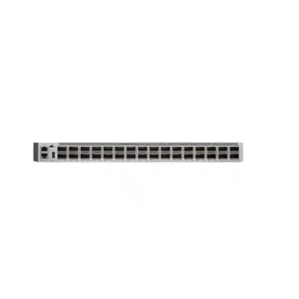
Cisco Catalyst C9500-32C Network Switch in UAE
The Cisco Catalyst C9500-32C is a high-density, high-performance fixed core switch for organizations that need 40G and 100G fiber at the campus core, distribution layer, aggregation boundary or routed service edge. With 32 QSFP28 ports, Cisco UADP 3.0 programmable switching silicon, up to 6.4 Tbps of switching capacity and up to 2 billion packets per second of forwarding performance, the platform is engineered for enterprise networks where deterministic throughput, resilient design, advanced routing, segmentation and automation matter more than basic access-layer port count.
Direct answer: who should deploy the C9500-32C?
Choose the Cisco Catalyst C9500-32C when your design calls for a dense 100G or 40G fiber switch at the core or distribution layer and you want the operational model of Cisco Catalyst IOS XE rather than a data-center-only switching architecture. It is especially well suited to large campuses, universities, government entities, healthcare networks, airports, hospitality groups, multi-building commercial estates, industrial sites, financial institutions and large UAE enterprises consolidating multiple 10G, 25G, 40G or 100G uplinks into a resilient core.
The most important sizing question is not simply whether 32 ports are enough. A correct design also considers how many ports will run natively at 100G, how many will run at 40G, whether supported breakout connectivity is required, how the pair will be virtualized or routed, how many routes and MAC entries are expected, whether MPLS or EVPN-VXLAN is in scope, the required software tier, optical reach, redundancy objectives, rack airflow and the expected growth curve over three to seven years. FourTeck can assist with architecture and implementation through the FourTeck UAE team before a bill of materials is finalized.
Cisco C9500-32C technical snapshot
Port architecture
32 QSFP28 front-panel interfaces supporting 40 Gigabit Ethernet and 100 Gigabit Ethernet. The platform is positioned as a dense fiber core and distribution switch, with breakout options available for supported optics and cabling combinations when lower-speed fan-out is required.
Switching performance
Up to 6.4 Tbps switching capacity and up to 2 Bpps forwarding performance. Cisco specifies line-rate performance for packet sizes of 187 bytes and above, making the platform suitable for very high-bandwidth aggregation and routed core roles.
Switching silicon
Cisco UADP 3.0 ASIC technology provides a programmable pipeline and flexible allocation of forwarding resources, including Layer 2, Layer 3, ACL, QoS, NetFlow, tunnel and segmentation functions through platform SDM templates.
Resiliency
Cisco StackWise Virtual can combine two compatible switches into a logical system, enabling multichassis EtherChannel designs, Stateful Switchover and operationally simplified high availability for critical campus backbones.
Physical format
1RU fixed chassis, approximately 1.73 × 17.5 × 21.2 inches and about 25.64 lb with two power supplies and built-in fan assembly according to Cisco platform specifications. This density is valuable in constrained MDF and data-room racks.
Software platform
Cisco IOS XE provides enterprise routing, telemetry, programmability, model-driven APIs, software maintenance capabilities and a familiar operational environment for teams already standardized on Catalyst 9000 switching.
32-port QSFP28 architecture and practical port planning
The C9500-32C front panel provides 32 high-speed QSFP28 interfaces. For a campus architect, this is more useful than simply reading “32 ports” on a specification sheet. Each port can become a strategic connection point to distribution blocks, data-center aggregation, WAN routers, firewalls, wireless controllers, service-provider handoffs or a second core switch. At 100G, a pair of C9500-32C switches can support a very large amount of north-south and east-west traffic while keeping the core physically compact.
The platform supports both 40G and 100G operation on the QSFP family of interfaces. This makes it practical for phased migrations where older 40G distribution uplinks continue to run while new buildings or aggregation blocks are introduced at 100G. A network does not need to replace every optic on day one. Instead, architects can establish a transition plan in which existing 40G links are retained for lower-demand segments and 100G is deployed for the most bandwidth-intensive paths. The result is a more controlled modernization project with fewer simultaneous changes.
Breakout support can also be significant. Cisco lists lower-speed port density possibilities using supported breakout cabling, including up to 96 10G or 96 25G logical interfaces in applicable breakout configurations. In practice, breakout design must be checked per port group, transceiver family, cable type and current IOS XE support. It is unwise to assume that every conceptual fan-out combination is supported in every software train. A bill of materials should therefore map each physical QSFP28 port to its intended optic or DAC/AOC, destination device, required distance, fiber type and breakout mode.
For UAE deployments, port planning should also reserve capacity for growth and failure scenarios. A core that is designed to use all 32 interfaces on day one leaves no comfortable room for emergency migration, temporary bypass links, new buildings or bandwidth expansion. A practical design commonly reserves spare ports and spare optical inventory. It is also useful to separate port plans into infrastructure links, peer/core links, security services, WAN or DCI links, temporary migration ports and future capacity. This turns a switch purchase into a manageable lifecycle plan rather than a one-time hardware installation.
UADP 3.0 performance: what 6.4 Tbps and 2 Bpps mean in design terms
Throughput headroom
A 32-port switch populated with 100G links has 3.2 Tbps of one-direction aggregate front-panel bandwidth. Cisco’s stated switching capacity of up to 6.4 Tbps reflects the full-duplex switching requirement for that interface density. This matters for nonblocking campus cores where many high-speed links can be active simultaneously.
Packet-rate capability
Bandwidth alone is not enough. Smaller packets create more forwarding work per second. The C9500-32C is specified for up to 2 Bpps, giving architects an important packet-processing indicator for routing, service aggregation, telemetry-rich environments and networks with large numbers of concurrent flows.
The UADP 3.0 architecture is particularly relevant because enterprise core requirements are not static. One customer may need very large Layer 3 tables, another may need higher MAC scale, another may prioritize security ACLs, while an SD-Access border may need different tunnel and policy resources. Cisco addresses this through flexible SDM templates that allocate hardware resources according to role. For the C9500-32C and related UADP 3.0 high-performance models, Cisco provides distribution, core, NAT and SD-Access templates. The distribution template prioritizes MAC and security resources; the core template increases routing resources; the NAT template allocates more capacity for Layer 3/NAT use; and the SD-Access template is tuned for fabric functions.
For example, Cisco’s published template values show that the distribution template can allocate approximately 82,000 MAC entries, while the core template uses a different balance with approximately 32,000 MAC entries and greater emphasis on route capacity. The same template framework changes PBR/NAT, ACL, NetFlow and tunnel allocations. This is why sizing a C9500-32C should be based on the actual intended network role. A switch can have enormous raw bandwidth yet still need the right hardware resource template for a route-heavy, policy-heavy or tunnel-heavy deployment.
The platform also provides a unified packet buffer architecture, with Cisco documenting up to 36 MB of unified buffer per ASIC for Catalyst 9500 UADP platforms. Buffering becomes important in microburst scenarios, speed transitions and oversubscribed aggregation. While buffer size is only one part of congestion behavior, enterprise architects should consider traffic profiles, queue design, uplink ratios and application sensitivity instead of relying only on link bandwidth. The C9500-32C’s combination of high-speed interfaces, hardware QoS and programmable silicon makes it capable of supporting these designs when configured correctly.
Layer 3 routing for enterprise core, WAN edge and aggregation
A core switch is often asked to do far more than VLAN switching. The Catalyst 9500 family is designed as an enterprise core and distribution platform with broad routing support. Depending on the selected software license and feature set, the platform supports technologies including OSPFv2 and OSPFv3, EIGRP and EIGRPv6, IS-IS, BGP for IPv4 and IPv6, IPv6 routing, Protocol Independent Multicast modes and routed subinterfaces. This allows the C9500-32C to function as a routed campus core, distribution router, service aggregation node or a collapsed-core device where Layer 3 boundaries are intentionally moved closer to the access network.
In modern campus design, Layer 3 to the distribution or even to the access boundary can significantly reduce spanning-tree failure domains. A C9500-32C pair can terminate routed uplinks from multiple distribution blocks using equal-cost multipath routing. This removes the need to stretch unnecessary Layer 2 domains across the entire campus and gives network teams deterministic convergence characteristics. Where legacy VLAN extension remains necessary, the same platform can continue to support Layer 2 functions, allowing migration to proceed incrementally.
For large UAE organizations with multiple WAN carriers or data centers, BGP can be particularly useful. The C9500-32C can participate in internal or external BGP designs, support policy-driven route exchange and connect to MPLS, SD-WAN or internet-edge infrastructure depending on the surrounding architecture. The switch should not automatically replace a purpose-built internet edge router or firewall; the correct role depends on services such as full internet tables, NAT scale, DDoS design, WAN encapsulation, encryption and operational boundaries. However, its high-speed routing capability gives architects considerable flexibility at internal aggregation and managed WAN handoff points.
Route scale must still be engineered. The C9500-32C’s programmable SDM resources mean route capacities vary by template and entry type. Direct hosts, indirect prefixes, IPv4, IPv6, multicast, adjacency and policy resources consume different hardware tables. FourTeck recommends collecting actual routing tables from the existing network, applying realistic growth factors and checking the proposed IOS XE release and SDM template before cutover. This is more reliable than treating a single “maximum routes” number as universally applicable.
EVPN-VXLAN, MPLS and segmentation capabilities
The C9500-32C can participate in architectures that extend beyond traditional campus VLANs. Cisco documents support for BGP EVPN with VXLAN on Catalyst 9500 platforms, including fabric spine, leaf and border roles, Layer 2 and Layer 3 VNIs, distributed anycast gateway functions and multihoming capabilities on the Catalyst 9500 line. This gives enterprise architects a path toward scalable segmentation and overlay networking without immediately moving every function into a data-center switching family.
EVPN-VXLAN is useful where organizations need to separate tenants, departments, production zones or operational networks while maintaining consistent control-plane signaling. EVPN uses BGP to distribute endpoint and reachability information, while VXLAN provides the encapsulation mechanism for virtual networks over an IP underlay. On the C9500-32C, these functions can be combined with high-speed 100G underlay connectivity. The design still requires disciplined MTU planning, routing policy, VNI mapping, redundancy design and operational monitoring.
MPLS is another differentiator for specialized enterprise and service aggregation use. Cisco documents MPLS Layer 3 VPN, Ethernet over MPLS, VPLS, MPLS over GRE and MPLS Traffic Engineering capabilities on the Catalyst 9500 platform. These functions are valuable for organizations with complex multi-VRF backbones, managed campus services, metro-style connectivity or private WAN designs. The applicable license level and software release should be confirmed because advanced features may require Network Advantage and a corresponding subscription tier.
Segmentation is ultimately a business requirement rather than a protocol choice. A healthcare group may segment clinical systems, guest services, building management and administrative networks. A university may separate research, student, faculty, IoT and data-center domains. A government customer may require VRF-based separation between departments and services. The C9500-32C provides multiple technical mechanisms—VRFs, routed interfaces, ACLs, policy, MPLS, VXLAN and SD-Access—to support those outcomes. The right choice depends on scale, operational skill, existing Cisco investment and the desired level of automation.
StackWise Virtual and high-availability core design
Most C9500-32C deployments should be evaluated as a resilient pair rather than as a standalone switch. Cisco StackWise Virtual allows two compatible Catalyst 9500 systems to operate as one logical switching system from the perspective of downstream devices and many operational workflows. Multichassis EtherChannel can span the two physical switches, enabling a distribution switch, server aggregation device or firewall cluster to connect redundantly to both chassis while using a single port-channel abstraction.
The core advantage is failure-domain reduction. If a single physical chassis, supervisor process, power source, cable path or maintenance event affects one member, properly designed traffic can continue across the peer. Stateful Switchover and StackWise Virtual support are intended to improve service continuity, while In-Service Software Upgrade capabilities can reduce disruption during selected maintenance scenarios. Actual hitlessness depends on feature, software release, topology and endpoint behavior, so maintenance procedures should still be validated in a lab or controlled window.
A strong pair design uses diverse physical paths. The two C9500-32C switches should ideally be installed on independent rack power feeds, connected to separate PDUs and UPS circuits, and cabled so critical downstream systems have links to both members. StackWise Virtual links and dual-active detection paths require careful planning so the control architecture remains stable under partial failure. When optics are used between separated racks or rooms, distance, fiber type and patch-panel loss budgets need to be documented.
High availability is not achieved by buying two switches alone. Redundancy must be end to end. Distribution uplinks, firewall interfaces, WAN handoffs, DNS, DHCP, routing adjacencies, server NIC teams and monitoring systems all need failure behavior that matches the core design. During implementation, FourTeck can coordinate the switching layer with adjacent security infrastructure through Firewall Dubai, helping ensure that multichassis connectivity and routing handoffs are designed as one system rather than isolated equipment changes.
Security architecture: MACsec, trustworthy boot and policy enforcement
Link encryption and integrity
Catalyst 9500 UADP platforms include hardware support for IEEE 802.1AE MACsec using 256-bit AES-GCM. MACsec can protect Ethernet links against interception and tampering, making it useful for inter-building fiber, carrier-managed dark fiber and other trusted-but-exposed Layer 2 transport scenarios.
Platform trust
Cisco documents image signing, Secure Boot and the Cisco Trust Anchor Module across Catalyst 9500 platforms. These controls help establish hardware and software authenticity during boot and reduce the risk of unauthorized software being introduced into the trusted network infrastructure.
At the forwarding layer, the C9500-32C supports hardware ACLs and policy mechanisms that can enforce segmentation at high speed. Security ACL scale varies with SDM template. For UADP 3.0 high-performance Catalyst 9500 models, Cisco publishes substantial security ACL resources, with the exact balance changing by distribution, core, NAT or SD-Access role. This matters in large networks where ACLs are not limited to a few interface filters but may represent policy boundaries between VRFs, server zones, campus segments and infrastructure services.
The switch can also fit into identity-driven campus designs. In Cisco SD-Access architectures, the C9500 can serve fabric control-plane and border roles. Security Group Tags and policy constructs can then be used to express access decisions independently from traditional IP addressing. This approach is attractive for large organizations that want consistent segmentation across wired, wireless and routed campus infrastructure.
Security planning should always distinguish what the switch does from what a next-generation firewall does. The C9500-32C is excellent at high-speed segmentation, encrypted links, routing policy, ACL enforcement and infrastructure trust. It is not a substitute for application inspection, threat prevention, sandboxing, web filtering or user-aware internet security. In many enterprise designs, the C9500-32C provides the resilient high-speed core while firewalls enforce north-south or inter-zone security at selected boundaries.
QoS, multicast and time-sensitive enterprise traffic
Enterprise cores carry many traffic classes at once: voice, video, wireless tunneling, backup, VDI, storage synchronization, building automation, surveillance, ERP, cloud access and ordinary user traffic. The C9500 platform supports Cisco Modular QoS CLI, strict-priority queuing, class-aware queuing, policing, shaping and two-level hierarchical QoS. These capabilities allow architects to preserve service levels during congestion rather than relying on best-effort forwarding alone.
QoS should be designed from edge to core. Marking policies at the access layer need to be trusted, rewritten or policed deliberately. The C9500-32C can then queue traffic according to business importance on high-speed aggregation links. At 100G, sustained congestion may seem unlikely, but microbursts can still occur when many lower-speed interfaces converge on a smaller number of uplinks or when multiple servers transmit simultaneously. Correct queue and buffer design can protect real-time applications even when average utilization appears low.
For multicast environments, Catalyst 9500 supports PIM Sparse Mode, PIM Source-Specific Multicast and additional multicast routing functions. This can be important for financial market data, IPTV, large digital signage systems, campus video distribution and certain operational technology applications. Multicast scale is influenced by the selected SDM template; Cisco’s core template, for example, allocates more multicast routing resources than a distribution-focused template.
Precision Time Protocol support is another useful capability. Cisco documents IEEE 1588v2 PTP on Catalyst 9500 platforms, enabling sub-microsecond class synchronization scenarios when the full network design supports it. This can be relevant to industrial automation, broadcast, financial and other timing-sensitive environments. Architects should validate end-to-end clocking requirements because PTP design involves grandmaster selection, boundary or transparent clock behavior, path asymmetry and operational monitoring—not merely enabling a feature on the core switch.
Automation, telemetry and IOS XE operational model
Cisco IOS XE is a major reason many enterprises select the Catalyst 9500 family for the campus core. It combines traditional CLI workflows with model-driven programmability. The platform supports NETCONF, RESTCONF, gNMI/gNOI, YANG configuration and operational models, streaming telemetry, Plug and Play and zero-touch provisioning options. Network teams can therefore move from manual device-by-device changes toward controlled automation without abandoning familiar Cisco operational practices.
Model-driven APIs are particularly valuable in large UAE environments with dozens or hundreds of network devices. Instead of logging into each switch to verify VLANs, routing neighbors or interface policy, teams can collect structured operational state centrally. Configuration pipelines can validate intended changes before deployment, and telemetry can feed dashboards or analytics systems in near real time. This supports faster incident response and reduces configuration drift.
Cisco IOS XE also supports on-box Python capabilities and container-based application hosting on supported Catalyst 9500 configurations. The C9500 high-performance platform can use supported SSD storage options for application hosting, creating opportunities for local agents, monitoring utilities or edge functions. Such deployments should be governed carefully because the switching platform’s primary responsibility remains network forwarding and control-plane stability.
Organizations modernizing operations can combine the C9500-32C with centralized Cisco management and assurance tooling, or integrate it into existing automation frameworks. FourTeck’s IT Services UAE team can support configuration standardization, migration scripting, monitoring integration and operational documentation so the new core is delivered with a repeatable management model rather than an isolated set of CLI commands.
Licensing: Network Essentials, Network Advantage and current subscriptions
The C9500-32C is commonly ordered in two main base license variants: C9500-32C-E with Network Essentials and C9500-32C-A with Network Advantage. Cisco’s current ordering and licensing framework pairs the perpetual network stack license with a software subscription tier at initial purchase. Cisco has evolved naming and packaging over time, including Cisco DNA subscriptions and newer Catalyst Software Subscription terminology, so the exact commercial configuration should be validated at quotation time.
Network Essentials is intended for organizations that need the fundamental enterprise switching and routing capabilities appropriate to their design. Network Advantage adds advanced functionality used in more sophisticated routing, segmentation and fabric scenarios. The correct tier is determined by required features rather than by port speed. A customer can buy a 100G switch and still choose the wrong software tier if advanced routing, MPLS, EVPN, policy or fabric features are expected later.
Subscription duration also matters operationally. Cisco commonly offers multiple term lengths. Procurement teams should align subscription renewal dates with enterprise licensing calendars and support contracts to avoid fragmented renewals. When a subscription expires, the base perpetual network license remains a separate consideration from subscription-delivered capabilities; exact behavior should be reviewed against the software version and Cisco’s current licensing policy.
A complete FourTeck quote should therefore identify the hardware base SKU, Network Essentials or Network Advantage level, subscription tier and term, power supplies, fans, optics, patching, support coverage and any implementation services. This prevents the common mistake of comparing only chassis prices. Two quotes for “C9500-32C” can differ materially because one may include the correct redundant PSU, optics and software while another contains only the base configuration.
Optics and cabling: design the link budget before ordering
A 100G core switch is only as useful as the optical design around it. The C9500-32C uses QSFP28 interfaces, and the correct transceiver depends on speed, distance, fiber type, connector standard and the equipment at the far end. Short intra-rack connections may use suitable direct-attach or active optical cables. Building-to-building links may use multimode or single-mode optical modules. Longer campus, metro or data-center-interconnect paths may require extended-reach optics and careful optical budget calculations.
Fiber plant documentation should be reviewed before optics are purchased. Engineers need to know whether each path is OM3, OM4, OM5 or single-mode OS2, the connector type, number of patch panels, estimated insertion loss, existing wavelength plan and whether the path is shared with passive optical equipment. Never select an optic solely from a theoretical maximum distance. Real-world loss, connector cleanliness, patch quality and future maintenance margin all affect link reliability.
Breakout designs add another layer. A QSFP28 interface may connect through supported breakout assemblies to multiple lower-speed interfaces, but both ends need compatible signaling and current software support. Breakout is especially useful when consolidating 10G or 25G devices during a migration, yet it should be documented port by port so operations teams understand which logical interfaces map to which physical cable legs.
FourTeck recommends an optics schedule as part of every C9500-32C project. The schedule should include source port, destination port, required speed, fiber type, estimated distance, optic part number, patch-cord type, redundancy group and spare requirement. This small amount of engineering prevents a large class of deployment delays. It also makes future troubleshooting much faster because field teams can immediately identify the intended optical path and transceiver pairing.
Power, cooling and rack planning for UAE facilities
The C9500-32C is a 1RU switch, but high-density 100G switching still requires careful facilities planning. Cisco specifies support for dual 1+1 redundant power supplies on Catalyst 9500 systems, and the C9500-32C power-supply matrix uses 1600W AC or DC options. A second PSU should be included for production cores where single-component power resilience is required. Each supply should be connected to an independent PDU or power path where the facility design allows it.
Cisco specifies AC input ranges suitable for enterprise power environments, but local electrical design must still account for connector type, circuit capacity, UPS load and redundant feed topology. Facilities teams should verify that both PSUs are not accidentally connected to the same single point of failure. In larger data rooms, A and B feeds should be mapped all the way back to independent UPS or generator paths where the availability requirement justifies it.
Cooling is equally important in the UAE. Cisco’s environmental specification for the C9500-32C includes normal operation from 0°C to 40°C at higher supported altitudes, with defined allowances up to 45°C at lower altitude. Those values are equipment operating limits, not recommended room targets. A properly managed data room should maintain controlled inlet temperatures, clean airflow and adequate cold-aisle delivery. Dust control is particularly important in regional environments because clogged filters, contaminated connectors and blocked airflow can reduce reliability long before electronic limits are reached.
The C9500-32C uses field-replaceable fan trays, with Cisco listing up to five C9K-T2 fan trays for this model. Fan direction, rack orientation and surrounding equipment should be checked so intake and exhaust patterns are consistent. Mixing devices with opposing airflow in a tightly packed rack can create hot-air recirculation even when total room cooling capacity appears sufficient.
Physical planning should also allow for the chassis depth, cable bend radius and front/rear service clearance. The C9500-32C is approximately 1.73 inches high, 17.5 inches wide and 21.2 inches deep. QSFP cabling can become dense, so vertical cable managers and deliberate fiber routing are recommended. If the network core shares a rack with servers, storage or security appliances, FourTeck can coordinate the wider rack and infrastructure plan with the Server Dubai team.
UAE deployment patterns for the C9500-32C
Large campus core
Deploy two C9500-32C switches as the campus core. Distribution blocks connect using dual 40G or 100G links, with routed ECMP or multichassis EtherChannel depending on the architecture. The design can consolidate many buildings while preserving high-speed capacity for wireless, video, voice and enterprise application traffic.
Collapsed core
For medium-to-large sites, the pair can combine core and distribution functions. High-speed server, firewall, WAN and access aggregation links terminate directly on the C9500-32C pair. This reduces tiers and equipment count but requires disciplined resource, port and failure-domain planning.
SD-Access border/control plane
In Cisco SD-Access, the C9500 family can perform fabric border and control-plane roles. The 32C model provides dense high-speed links for connecting fabric sites to shared services, data centers, WAN infrastructure and external routing domains.
EVPN-VXLAN aggregation
Organizations building an IP fabric can use the C9500-32C in EVPN-VXLAN roles where Catalyst operational consistency is preferred. The 100G interfaces provide strong underlay capacity while VRFs, VNIs and BGP EVPN deliver segmentation and control-plane scalability.
For government and critical-infrastructure networks, the switch is often attractive because it combines high-speed routing, robust segmentation and Cisco’s enterprise operational ecosystem. Designs may use separate VRFs for corporate, operational, guest, CCTV, building management and management-plane traffic. Redundant 100G connections can preserve capacity during link or chassis failures. Access to sensitive services can be restricted through ACLs, route policy and firewall boundaries.
In hospitality and large commercial real estate, network traffic patterns are diverse. Guest internet, IP telephony, IPTV, Wi-Fi, CCTV, digital signage, access control, building automation and tenant services may all cross the same core. The C9500-32C offers enough high-speed interface density to aggregate multiple distribution stacks or buildings while QoS, multicast and segmentation maintain service separation. The key is to design logical boundaries deliberately rather than allowing every operational system to share a flat campus VLAN structure.
Sizing methodology: how to determine whether 32 × 100G is the right platform
A professional sizing exercise starts with topology and traffic, not with a preferred SKU. First count all required physical connections: distribution blocks, firewalls, WAN routers, data-center switches, wireless aggregation, storage or service links, management connections and peer links. Then define speed for each connection today and at the target design horizon. A 10G link that is already at 60 percent utilization should not necessarily remain 10G simply because it works today; growth and failure scenarios may justify 25G, 40G or 100G.
Second, calculate resilient capacity. If two C9500-32C switches form a pair, the network should normally survive the loss of one link, one port-channel member or one chassis without unacceptable congestion. This means bandwidth should be evaluated in N-1 conditions. A design that runs at 70 percent of aggregate capacity in normal operation can become oversubscribed after a failure. Critical traffic classes, backup windows and peak business periods should all be included.
Third, examine forwarding scale. Collect current MAC address counts, IPv4 and IPv6 routes, ARP/ND entries, multicast groups, ACL usage, NetFlow requirements, VRFs, VLANs and tunnel endpoints. Apply a growth factor appropriate to the organization. The C9500-32C has flexible hardware templates, but the selected template must provide sufficient headroom for the intended role. A route-heavy core and a MAC-heavy distribution switch may use the same hardware with different SDM allocations.
Fourth, validate software feature requirements. List every protocol and feature that must operate on day one and every feature planned over the lifecycle: OSPF, BGP, EIGRP, IS-IS, multicast, MPLS, EVPN-VXLAN, SD-Access, MACsec, NetFlow, automation, telemetry and policy. Map those functions to Network Essentials or Network Advantage and the current subscription model. This protects the project from licensing surprises during implementation.
Finally, include physical and commercial constraints. Check rack depth, power feeds, airflow, optic availability, fiber readiness, lead times, support coverage and spare strategy. If those factors are addressed early, the C9500-32C can be deployed as a long-life backbone platform rather than a hardware purchase that immediately creates secondary infrastructure problems.
C9500-32C versus nearby Catalyst 9500 choices
| Model | Primary port profile | Best fit | Design note |
|---|---|---|---|
| C9500-32C | 32 × 40/100G QSFP28 | High-density campus core and aggregation | Best when many native 100G ports are required in 1RU. |
| C9500-32QC | Higher 40G density with a smaller 100G profile | 40G-heavy legacy core modernization | Useful where 40G remains dominant and full 32-port 100G density is unnecessary. |
| C9500-48Y4C | 48 × 1/10/25G plus 4 × 40/100G | 25G-heavy distribution or server aggregation | Better when endpoint-facing 25G density is more important than 100G density. |
| C9500X family | Newer high-speed options including 400G on selected models | Next-generation cores requiring 400G or higher scale | Consider when the design horizon clearly requires 400G, deeper scale or newer Silicon One architecture. |
The C9500-32C remains a strong choice when 100G is the key requirement and the organization wants Cisco Catalyst IOS XE, UADP-based enterprise features and mature campus-core capabilities. It avoids the cost and complexity of moving to 400G when that bandwidth is not needed, while still providing enough density for substantial campus or aggregation designs.
However, new greenfield projects should explicitly compare the C9500-32C with current C9500X options. If 400G uplinks, significantly larger tables, deep buffers or a longer performance runway are required, the newer platform may be justified. If the environment primarily needs dozens of 100G links and established Catalyst 9500 operational compatibility, the C9500-32C can deliver a more targeted fit. The decision should be based on five-year traffic and feature projections rather than launch date alone.
Migration blueprint from an existing campus core
A C9500-32C migration should be treated as a controlled network transformation. The safest process begins with discovery. Export interface descriptions, VLAN databases, spanning-tree roles, routing tables, first-hop gateway configurations, HSRP/VRRP state, ACLs, multicast configuration, QoS policies, SNMP settings, NTP, AAA, syslog, NetFlow and all physical port mappings from the existing core. Document which functions must be preserved and which should be redesigned.
The target design should then decide whether to replicate the old topology or improve it. Many legacy cores carry excessive Layer 2 because that was easiest when the campus was built. A migration to C9500-32C is an opportunity to introduce routed uplinks, reduce spanning-tree domains, standardize port channels, consolidate obsolete VLANs and improve segmentation. Changes should be staged so that troubleshooting remains manageable.
Before production cutover, load the selected IOS XE release, validate licensing, configure management-plane security, build the StackWise Virtual pair if required, apply the correct SDM template and establish baseline routing and monitoring. Optical links should be light-level tested where practical. Preconfigure downstream interfaces and use clear descriptions that identify device, port, path and circuit information.
During cutover, migrate links in logical groups. A building distribution block can move one redundant path at a time while reachability and routing convergence are monitored. Firewalls and WAN handoffs should have rollback plans because they often represent high-impact boundaries. After each phase, verify interface errors, routing neighbors, MAC learning, ARP/ND, multicast, latency, application reachability and monitoring alerts.
Post-migration, capture a new baseline. Record CPU, memory, interface utilization, queue drops, optical receive levels, route counts and hardware resource usage under normal peak load. Those measurements become the reference for future incident analysis. A migration is complete only when documentation, diagrams, backups, credentials handling, support records and operational handover are updated.
Operational runbook for production C9500-32C environments
Daily and weekly health
Track interface errors, transceiver alarms, routing adjacency changes, StackWise Virtual state, CPU and memory, fan and PSU status, temperature, queue drops and hardware table utilization. Alerting should distinguish transient events from conditions that threaten redundancy.
Configuration governance
Back up configuration after approved changes, retain version history, use centralized AAA, restrict privileged access, standardize NTP and syslog and review configuration drift. Automation should be tested against representative devices before broad rollout.
Software lifecycle
Use a supported IOS XE train aligned to Cisco guidance, required features and organizational maintenance policy. Review field notices and security advisories, validate upgrade paths and preserve rollback images and configuration backups before maintenance.
Spares strategy
Keep critical optics, patch leads and where justified spare fan or power components available locally. For environments with strict recovery objectives, consider a cold spare chassis or a support level that guarantees acceptable hardware replacement times.
Optical monitoring deserves special attention. 100G links can remain operational while gradually losing optical margin because of contamination, poor patching or fiber degradation. Capture transmit and receive levels during commissioning and compare future alarms against that baseline. When a link flaps, inspect physical-layer data before assuming a routing or software problem.
Hardware resource utilization should also be included in operational checks, especially in networks with frequent policy or routing growth. ACLs, routes, MAC entries, NetFlow and tunnel resources are finite ASIC allocations. Monitoring them before exhaustion gives engineers time to adjust SDM templates, reduce unnecessary state or plan hardware expansion during a normal maintenance cycle instead of during an outage.
Troubleshooting framework for high-speed core incidents
When a production core has a problem, troubleshooting should proceed from physical certainty to protocol state. Start with power, fans, environmental status and link state. Check transceiver diagnostics, receive power, interface errors, CRCs, lane alarms and port-channel member consistency. A surprising number of “routing” incidents begin with dirty fiber, marginal optics, incorrect patching or a failed member in a redundant bundle.
Next verify Layer 2 and Layer 3 adjacency. Confirm MAC learning, VLAN membership, spanning-tree state where relevant, ARP/ND resolution and routing-neighbor health. For OSPF, BGP, EIGRP or IS-IS, compare neighbor changes against syslog timestamps. For StackWise Virtual, inspect peer and dual-active-detection state. For port channels, confirm both ends agree on member state and LACP behavior.
If performance degradation rather than outage is reported, inspect queue drops, microbursts, interface utilization, QoS classification and traffic asymmetry. A 100G interface can still suffer application impairment if a critical queue is dropping or if return traffic is taking a different congested path. Flexible NetFlow and telemetry can help identify top talkers, unexpected flows and traffic shifts.
For control-plane symptoms, check CPU, memory, process activity, logging volume and management traffic. Determine whether a routing event, broadcast storm, telemetry flood or automation mistake preceded the issue. Do not make broad configuration changes until the failure domain is understood. A resilient core is best restored by changing one variable at a time while preserving evidence.
Finally, capture a problem record that includes timestamps, topology, affected services, command outputs, interface counters, software version, recent changes and the recovery action. This documentation shortens vendor support escalation and helps prevent recurrence. Enterprise networks become more reliable when each incident improves the operational runbook rather than disappearing after service is restored.
Procurement considerations for Dubai and the wider UAE
Enterprise switching projects in the UAE frequently involve more than obtaining a chassis. A production-ready C9500-32C solution may include the -E or -A base SKU, the correct current software subscription, a second 1600W power supply, fan configuration, rack accessories, 40G/100G optics, breakout cables, fiber patching, support coverage, installation, migration services and documentation. Comparing quotations without normalizing these components can produce misleading price differences.
Availability and lead time should be confirmed for every critical line item, especially optics and license subscriptions. A switch arriving without compatible transceivers does not advance a migration. For projects with fixed handover dates, spare optics and patch components should be included from the beginning. If the organization operates multiple UAE sites, standardizing on a controlled set of optic types can simplify inventory and fault replacement.
Support strategy should match business impact. A core serving thousands of users, building systems and data-center services may justify stronger response commitments than a lab or secondary site. Customers should review Cisco support entitlement, replacement expectations, software access and local engineering coverage. The required service level should be documented before purchase rather than selected after the first incident.
FourTeck can combine product supply with solution-level engineering, including design validation, implementation planning, optics mapping, rack readiness, migration and post-cutover support. For broader enterprise technology procurement beyond the switching layer, customers can also reference FourTeck Global for group-wide requirements while retaining UAE-focused delivery coordination.
Frequently asked technical questions
Is the C9500-32C a Layer 2 or Layer 3 switch?
It is an enterprise multilayer core and distribution switch. It supports advanced Layer 2 services and a broad set of Layer 3 routing technologies. The exact advanced feature set depends on software licensing and release.
Does every port support 100G?
The C9500-32C provides 32 QSFP28 interfaces designed for 40/100G operation. Actual use depends on compatible optics, cable assemblies and supported configurations.
Can it be used as a campus core pair?
Yes. This is one of its principal roles. StackWise Virtual, multichassis EtherChannel, resilient routing and dual power options make it suitable for high-availability campus core designs.
Can it support EVPN-VXLAN?
Cisco documents BGP EVPN-VXLAN capability on Catalyst 9500, including fabric roles and Layer 2/Layer 3 VNI functions. License and IOS XE release should be validated for the required design.
Does it support MPLS?
Catalyst 9500 supports MPLS technologies including L3 VPN, EoMPLS and traffic engineering functions. Advanced software licensing is normally relevant, so feature mapping should be confirmed before ordering.
Is it appropriate for a data center?
It can serve enterprise aggregation and routed roles that border or connect data-center environments. For data-center fabrics requiring specialized deep buffers, very high 400G density or Nexus-specific operational features, a different platform may be more appropriate.
Decision recap: when the C9500-32C is the strongest fit
Strong fit
Select the C9500-32C when you need dense native 100G/40G connectivity, a compact 1RU form factor, established Catalyst IOS XE operations, advanced enterprise routing and a resilient pair architecture.
It is particularly compelling for campus cores, large distribution layers, routed aggregation, SD-Access border/control-plane roles and enterprise EVPN-VXLAN or MPLS designs where 100G is the dominant high-speed requirement.
Re-evaluate the platform
Consider another Catalyst 9500 model when most required ports are 10G or 25G and only a few 100G uplinks are needed. The C9500-48Y4C can be a more natural fit for 25G-heavy distribution.
Consider C9500X when the design clearly requires 400G interfaces, newer Silicon One architecture, larger scale or a performance horizon beyond what 32 × 100G delivers.
Quotation input checklist
To receive a technically accurate C9500-32C quotation, provide the information below. If some details are unknown, FourTeck can derive them during a design review.
Topology and capacity
Number of core switches, downstream distribution blocks, required port speeds, expected 40G/100G mix, breakout needs, growth period and peak traffic estimate.
Software features
Required routing protocols, MPLS, EVPN-VXLAN, SD-Access, NetFlow, MACsec, multicast, automation, telemetry and Network Essentials or Advantage preference.
Optics and fiber
Distance for every link, fiber type, connector type, required transceiver family, breakout cable needs and spare optic quantities.
Facilities and support
Rack location, available depth, A/B power feeds, AC or DC requirement, airflow direction, UPS design, installation scope, migration window and support SLA.
Plan your Cisco Catalyst C9500-32C deployment with FourTeck UAE
A high-speed core switch should be purchased as part of an engineered system. FourTeck can help validate whether the C9500-32C is the right model, determine the required license tier, build the optical bill of materials, design StackWise Virtual or routed redundancy, review rack and power readiness and plan the migration from the existing network. The objective is to deliver a core that has sufficient performance and table headroom on day one while remaining operationally manageable throughout its lifecycle.
For organizations in Dubai, Abu Dhabi, Sharjah and across the UAE, the project can include supply, configuration, installation, migration assistance, testing and documentation. Multi-site customers can standardize templates and monitoring so each core follows the same engineering baseline. Where firewalls, servers or other infrastructure connect directly to the core, those dependencies can be included in the design rather than treated as separate purchases.
Request a solution review with your current topology, expected uplink count and software requirements. FourTeck will use those inputs to prepare a configuration and quotation that reflects the real deployment rather than a chassis-only estimate.

Reviews
There are no reviews yet.