
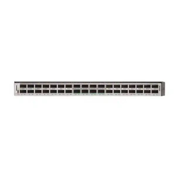
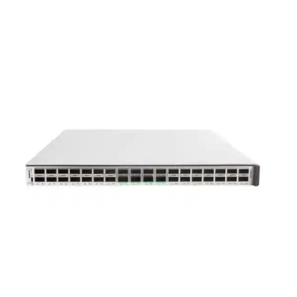
Cisco Catalyst C9500X-28C8D Network Switch
A high-density 100G/400G fixed core platform for modern campus backbones, aggregation layers and high-performance enterprise routing.
The C9500X-28C8D combines 28 QSFP28 interfaces capable of 40/100 Gigabit Ethernet with eight QSFP-DD interfaces capable of 40/100/200/400 Gigabit Ethernet. It is based on the Cisco Silicon One Q200 architecture and is designed for organizations that need far more than raw port speed: deterministic forwarding, flexible forwarding scale, deep buffering, encryption, segmentation, high availability, automation and the operational consistency of Cisco IOS XE. For UAE enterprises modernizing a campus core, consolidating multiple aggregation tiers, connecting data-centre or building distribution blocks, or preparing for 100G-to-400G growth, this model provides a compact 1RU platform with substantial headroom.
Direct answer
Choose the C9500X-28C8D when your design requires dense 100G access to the core plus native 400G uplink or inter-core capacity without moving to a modular chassis.
What the C9500X-28C8D is designed to do
The Cisco Catalyst C9500X-28C8D sits at the performance end of the fixed-form-factor Catalyst campus switching portfolio. It is not simply an access switch with faster uplinks. Its port layout, forwarding architecture and software feature set are oriented toward the core and distribution layers, where traffic from many access blocks converges and where a single forwarding decision can affect a large percentage of the enterprise. The platform is appropriate for large headquarters, university-style campuses, healthcare groups, hospitality estates, government environments, logistics hubs, financial organizations, multi-building commercial developments and distributed enterprises that need a robust routing and policy boundary.
In a conventional three-tier campus, the switch can operate as a high-capacity core joining distribution blocks at 40G or 100G and using one or more 400G links for inter-core, data-centre, service-provider or high-bandwidth backbone connectivity. In a collapsed-core architecture, it can combine distribution and core responsibilities where the design calls for high-speed routed access, resilient Layer 3 boundaries and reduced equipment count. It can also serve as an aggregation platform for dense 25G/100G downstream environments when suitable breakout optics and cabling are selected. The correct role depends on oversubscription, route scale, resilience objectives, optics distances and the expected growth of east-west and north-south traffic.
For UAE organizations, these considerations are particularly important in buildings where the switching core must serve many floors, campus blocks, surveillance systems, wireless controllers, application environments, internet edges, security stacks and private-cloud resources. FourTeck can align the switch configuration with wider LAN, security, server and structured infrastructure requirements through the FourTeck UAE portfolio, while implementation and lifecycle services can be scoped through FourTeck IT Services UAE.
Technical specification snapshot
Port architecture
28 × QSFP28 ports for native 40/100GbE plus 8 × QSFP-DD ports supporting 40/100/200/400GbE. Breakout designs can increase lower-speed interface density where supported optics, cables and software are used.
Forwarding engine
Cisco Silicon One Q200 ASIC with programmable forwarding architecture. Cisco specifies up to 12 Tbps switching capacity for the C9500X-28C8D platform and 8 billion packets per second forwarding.
Buffering
80 MB of dedicated low-latency buffer with support for up to 8 GB of High-Bandwidth Memory for deep packet buffering, helping the platform absorb bursts and microbursts in heavily aggregated networks.
System resources
Eight-core 2.3 GHz x86 CPU, 32 GB DRAM and 32 GB flash. The platform also supports local SSD capacity for application hosting when the required storage option and software capabilities are selected.
Physical format
1RU chassis measuring approximately 4.39 × 44.45 × 55.37 cm including fan/tray handles. A chassis populated with two power supplies and fans is approximately 13.28 kg.
Power and cooling
Supports 1500W AC or DC power supplies and six field-replaceable variable-speed fans. Fan direction is selectable by ordering the correct fan type; all installed fans must use the same airflow orientation.
Cisco Silicon One Q200 architecture: why it matters
The central architectural differentiator of the Catalyst 9500X generation is the Cisco Silicon One Q200. Cisco positions the Q200 as a next-generation core and edge switching ASIC, using a programmable forwarding pipeline and a 7 nm implementation. At the silicon level the architecture is capable of up to 12.8 Tbps full-duplex switching and 8 Bpps forwarding. For the C9500X-28C8D as a complete switch platform, Cisco lists up to 12 Tbps switching capacity. Keeping those two numbers separate is important during design review: the first describes the underlying silicon capability, while the second is the published platform performance figure for this model.
The value of this architecture is not only speed. Enterprise cores carry diverse workloads: latency-sensitive voice, collaboration, storage replication, virtual-machine traffic, large file transfers, internet-bound traffic, multicast video, wireless aggregation, security service chains and bursts from backup or analytics systems. A core ASIC must execute forwarding, classification, policy and encapsulation functions at high speed while maintaining predictable behavior under load. The Q200 provides a foundation for these duties without requiring external forwarding memory for core routing and switching functions, while High-Bandwidth Memory expands the buffering strategy for traffic patterns that exceed shallow on-chip queues.
Programmability also improves longevity. Networks rarely remain static for the full hardware lifecycle. New encapsulations, telemetry capabilities, security features and forwarding behaviors appear across successive IOS XE releases. A programmable pipeline gives Cisco more flexibility to evolve functions within the hardware envelope than a strictly fixed-function design. For a UAE enterprise planning a five-to-seven-year core lifecycle, that matters because the purchasing decision is not just about today’s 100G uplinks; it is about preserving operational relevance as access speeds, Wi-Fi generations, private cloud consumption and inter-site bandwidth continue to grow.
The practical design lesson is to size the C9500X-28C8D as a system, not as a headline-throughput number. Review actual interface combinations, breakout requirements, route and MAC scale, encryption needs, traffic profiles, oversubscription ratios, redundancy architecture and expected software features. A technically sound core design uses the ASIC’s headroom while validating that optics, cabling, software licensing and operational processes are equally ready for the intended service.
28 × 100G plus 8 × 400G: reading the port map correctly
The C9500X-28C8D front-panel capacity is built around two high-speed interface groups. Twenty-eight QSFP28 ports support 40 Gigabit Ethernet and 100 Gigabit Ethernet operation. Eight QSFP-DD ports extend the speed range to 40G, 100G, 200G and 400G. This gives the switch substantial flexibility when it is introduced into an environment that is migrating gradually rather than changing every connection simultaneously. Existing 40G links can coexist with 100G distribution uplinks, while selected backbone, inter-core or service-facing connections can move to 200G or 400G.
The port-density table also needs to be interpreted in the context of breakout. Cisco publishes multiple achievable densities with supported breakout arrangements. Breakout allows a higher-speed physical port to operate as multiple logical lower-speed links when the port, transceiver or cable combination supports that mode. This can be useful for connecting groups of 10G, 25G, 40G, 50G or 100G devices without consuming a separate chassis. However, breakout is not a substitute for a proper port map. Different physical ports and optics have specific breakout capabilities, and hardware-capable maximums can depend on software support. Before procurement, map every planned endpoint to a specific front-panel port, lane mode, optic, cable assembly and remote-side interface.
For example, a campus core might dedicate separate 100G QSFP28 connections to two distribution switches in each building, reserve paired high-speed links for StackWise Virtual connectivity, allocate 400G QSFP-DD ports to a data-centre aggregation layer, and keep spare 100G or 400G interfaces for future expansion. Another design might use the 400G ports as multiple 100G breakout connections to increase density while retaining several native 400G interfaces for backbone growth. The right allocation depends on resilience and fault-domain boundaries rather than maximizing the number of lit ports.
Optics selection is part of the architecture. Link distance, fiber type, patch-panel count, connector cleanliness, polarity, insertion loss and remote platform compatibility all affect which transceiver is appropriate. In Dubai campuses with multiple buildings, the same switch may need short-reach multimode connections inside a data room and single-mode links across longer campus fiber. The bill of materials should therefore list transceiver type and quantity by link, not simply provide a generic total.
Switching capacity, packet rate and performance sizing
Cisco specifies up to 12 Tbps switching capacity and an 8 Bpps forwarding rate for the C9500X-28C8D. Switching capacity expresses aggregate data movement through the platform, while the packet-per-second figure is especially relevant when traffic consists of small frames. Two networks can transmit the same number of gigabits per second but impose very different forwarding loads if one uses large frames and the other uses many small packets. Core design should therefore consider both bandwidth and packet rate, particularly for security-heavy environments, large numbers of users, telemetry workloads or services that generate small flows at high frequency.
A useful sizing method starts with the downstream links. Add the usable capacity of distribution connections, then model realistic simultaneous utilization instead of assuming that every link will run at line rate continuously. Identify known peak windows such as virtual desktop login storms, cloud backup, analytics processing, CCTV retention transfers, software deployment, assessment periods in education, billing cycles, end-of-day ERP processing or scheduled replication. Next, determine whether the northbound links can carry those peaks while one critical path is unavailable. Resilient networks should be sized for failure conditions, not just normal conditions.
Oversubscription is not inherently a problem. It becomes a problem when it is accidental, undocumented or concentrated on links serving latency-sensitive applications. A C9500X-28C8D may aggregate many 100G interfaces while only a subset is active at high utilization at any instant. That is acceptable when traffic engineering and application patterns support it. Conversely, a smaller number of ports can still experience congestion when several high-volume sources converge on one egress. The deep-buffer architecture helps absorb bursts, but buffers should not be treated as a permanent capacity substitute.
For procurement, ask for a port-and-bandwidth worksheet that shows day-one links, expected three-year links, failure-state capacity and remaining spare interfaces. This turns the headline 12 Tbps number into an operational plan. It also highlights when an organization needs a second switch for resiliency, additional optics, higher-speed uplinks, or a different topology before hardware is installed.
Deep buffering and congestion behavior
Core traffic is inherently bursty. A distribution switch can receive traffic from many access switches at the same moment and forward it toward a smaller number of upstream links. Even when the average utilization looks comfortable, short microbursts can overflow shallow queues and create packet loss. Cisco’s Catalyst 9500X architecture combines 80 MB of dedicated low-latency buffer with up to 8 GB of High-Bandwidth Memory for deep packet buffering. This is a significant design characteristic for environments that experience many-to-one traffic patterns or speed transitions between interfaces.
Consider a 400G-to-100G transition. A 400G-connected resource can send at a rate far above a single 100G egress. If multiple sources also target that egress, a queue forms instantly. QoS determines which packets receive priority and which may be dropped, while buffer capacity determines how much burst can be absorbed before loss occurs. The same principle applies when multiple 100G distribution links converge on a WAN, firewall cluster, internet edge or server aggregation path. Deep buffering increases tolerance for transient mismatch, but sustained oversubscription still requires capacity planning.
Queueing policy should be based on applications, not arbitrary VLAN numbers. Real-time voice and collaboration, control-plane traffic, business-critical applications, bulk backup, guest traffic and default data typically have different latency and loss tolerances. Classification and marking should be consistent from access to core so the C9500X can preserve intent rather than trying to infer application importance at the congestion point. Where WAN or firewall bottlenecks exist, the end-to-end policy should align with those downstream constraints.
Buffering therefore supports performance engineering rather than replacing it. When FourTeck scopes a core refresh, traffic baselines, interface statistics, queue drops and peak-period behavior can be used to determine whether the new 100G/400G architecture is solving a capacity issue, a burst issue, or both. This distinction prevents overbuying in one area while leaving an actual bottleneck unchanged elsewhere.
Routing scale and flexible forwarding resources
The C9500X platform is built for more than simple campus default routing. Cisco publishes scale of up to 256,000 MAC addresses and up to 2 million IPv4 routes on the Catalyst 9500X family, with additional published scale for host routes, IPv6 routes, multicast and Flexible NetFlow entries. The exact usable scale for a production configuration depends on the selected custom SDM allocation and the mix of enabled features, which is why route-table planning should be part of the design rather than an afterthought.
Beginning with the C9500X software generation, custom SDM templates allow administrators to allocate forwarding resources according to network requirements. Cisco documents configurable ranges for MAC addresses, IPv4 and IPv6 host routes, MPLS labels, security objects and other resources. This flexibility is useful because core switches in different environments have very different table profiles. A campus with large Layer 2 domains may prioritize MAC scale, while a routed-access design may need more host routes. A service-rich core may consume additional ACL, policy-based routing, MPLS or security resources.
Designers should inventory route sources before choosing allocations. Count internal OSPF or IS-IS prefixes, BGP routes, summarized branch routes, VRF-specific entries, connected subnets, host routes, multicast state and any routes learned from WAN or data-centre systems. If the core will carry full or partial internet routes, validate the intended table size and policy carefully; many enterprises do not need a full internet table on the campus core and can maintain cleaner fault boundaries by keeping that function at the internet edge. The ability to scale does not mean every route should be imported.
IPv6 deserves equal attention. Dual-stack migrations increase table consumption because IPv4 and IPv6 coexist, and host discovery behavior differs from legacy IPv4 ARP. Capacity should be modeled with both protocol families active. A planned SDM profile, documented route policy and periodic scale monitoring provide a stronger operational posture than waiting for table exhaustion warnings after deployment.
Advanced Layer 3, multicast and service capabilities
Catalyst 9500 Series software supports enterprise routing functions required at a modern campus core, including IPv4 and IPv6 routing, multicast and advanced policy capabilities. Depending on IOS XE release and licensing tier, the family supports technologies such as BGP, OSPF, IS-IS, VRF, MPLS Layer 2 and Layer 3 VPN services, multicast VPN functions, NAT, LISP and EVPN/VXLAN-related use cases. Feature availability should always be checked against the target IOS XE release and license level before the final implementation is approved.
In routed campus designs, the C9500X-28C8D can form the control-plane boundary between distribution blocks, data-centre services, WAN connectivity and security zones. Route summarization at these boundaries reduces control-plane churn and improves troubleshooting. Equal-cost multipath can be used where the topology provides multiple active routed paths. VRFs can separate business units, operational technology, guest services, management networks or regulated environments while allowing controlled inter-VRF connectivity through approved security points.
Multicast remains important in sectors such as broadcast, hospitality, trading, surveillance, digital signage and enterprise video. A core must support the expected number of multicast groups, sources and receivers while maintaining proper rendezvous point, PIM and IGMP/MLD design. The C9500X has published multicast scale, but the actual design should account for both Layer 3 multicast routes and Layer 2 snooping state. In large estates, a poorly bounded multicast domain can consume resources and complicate fault isolation even when the hardware scale is sufficient.
The preferred architecture is therefore intentionally routed, segmented and summarized. High-performance hardware makes it possible to carry many services, but operational clarity comes from minimizing unnecessary dependencies. During migration, FourTeck can map existing VLANs, routing adjacencies, first-hop gateway functions and multicast requirements so that the new core improves topology rather than reproducing legacy complexity at a higher speed.
StackWise Virtual and high-availability design
Core availability is usually more important than individual switch availability. Cisco StackWise Virtual allows two compatible Catalyst switches to operate as a virtualized system from the perspective of connected devices while retaining two physical chassis. On Catalyst 9500X, StackWise Virtual support is available with the appropriate IOS XE software release, and Cisco documents Stateful Switchover support through the StackWise Virtual architecture. In-Service Software Upgrade support for Catalyst 9500X is available from later IOS XE releases, so the planned upgrade methodology should be validated against the exact release chosen for production.
A major operational advantage is Multichassis EtherChannel. Downstream or upstream devices can connect across both physical core switches while forming one logical port channel. This reduces reliance on spanning-tree blocking for those links and allows traffic to continue over the surviving member if a chassis, power feed, optic or link fails. It also simplifies many collapsed-core designs because connected distribution switches can use active links toward both core members.
High availability still requires physical diversity. Two switches installed in the same rack, powered by the same PDU and connected through the same cable pathway are not equivalent to a resilient core. Where building design permits, separate power feeds, UPS circuits, rack positions, fiber routes and upstream service paths should be considered. StackWise Virtual links should have sufficient bandwidth and redundancy for the intended control and data behavior. Dual-active detection and failover validation should be part of commissioning, not left as untested configuration.
Change management is equally important. Software maintenance, configuration backups, golden image selection and pre/post checks should be documented. The goal is a core that can survive not only hardware failure but also routine operational work. A well-designed C9500X pair provides the hardware foundation, while disciplined release management and physical diversity convert that foundation into actual service availability.
MACsec and enterprise security at the core
The Catalyst 9500X hardware supports line-rate 256-bit IEEE 802.1AE MACsec and WAN-MACsec capabilities. MACsec encrypts Ethernet frames across supported links, protecting data in motion at Layer 2 without requiring applications to change. This is valuable for inter-building fiber, metro Ethernet handoffs, data-centre interconnects and other links where organizations want cryptographic protection between network devices while preserving high throughput.
Encryption design must include key management, peer compatibility and operational procedures. The remote device must support a compatible MACsec mode, and the selected transceivers and link design must remain supported. Key rotation and authentication should be integrated with the organization’s identity and certificate processes where appropriate. On links crossing a service-provider network, WAN-MACsec applicability should be verified for the actual handoff type and Cisco software release. The presence of hardware support is the starting point, not the entire security architecture.
At the policy layer, Catalyst 9000 platforms can participate in segmentation and access-control designs using VRFs, ACLs, security group constructs and Cisco Software-Defined Access capabilities. A core can enforce boundaries between user, server, guest, management, IoT and operational technology domains while steering permitted traffic to firewalls or other security controls. For environments that require dedicated perimeter or internal segmentation security, FourTeck’s Firewall Dubai practice can be aligned with the switching architecture so route boundaries and firewall zones are designed together.
Security should also include the infrastructure itself. Separate management access, AAA, role-based permissions, secure logging, SNMPv3 or modern telemetry, control-plane policing, encrypted management protocols, authenticated NTP, configuration archiving and restricted out-of-band access reduce the attack surface. A high-performance core is a privileged system; its management plane should be treated with the same rigor as a critical server or security appliance.
QoS for voice, collaboration, applications and bulk traffic
Quality of Service in a 100G/400G core is still necessary. Higher bandwidth reduces congestion frequency but does not eliminate congestion, especially where traffic moves from faster to slower interfaces or converges on firewalls, WAN circuits and application clusters. The C9500X platform provides QoS classification and policy capabilities with configurable hardware resources. The design objective is to preserve end-to-end service intent rather than create isolated queue settings on the core.
A typical enterprise policy starts by identifying trusted marking boundaries. Access switches may trust markings from managed IP phones but remark untrusted endpoint traffic. Wireless infrastructure can map application categories to DSCP. Distribution and core switches should preserve validated markings and apply queue treatment consistently. Network-control traffic needs protection, real-time voice needs low latency and controlled loss, interactive video may require significant bandwidth, business-critical applications need predictable service, and backup or replication can generally tolerate delay more readily than voice.
The C9500X deep buffering capability is especially useful when multiple high-speed inputs feed an oversubscribed output, but queue design determines who benefits from that buffer. Giving bulk traffic unlimited queue space can increase latency for interactive flows. Conversely, overly small queues can cause unnecessary drops during microbursts. Baseline measurements, application requirements and observed queue statistics should guide tuning. Where the downstream bottleneck is a WAN router or firewall, shaping and hierarchical policy may belong on that device rather than the campus core.
A deployment should therefore include QoS validation traffic, not just ping tests. Voice-quality monitoring, synthetic application tests, interface drop counters and queue telemetry can verify that the intended policy survives the migration. This becomes particularly important when an old 10G/40G core is replaced by 100G/400G switching, because bottlenecks may simply move to another layer after the core itself is accelerated.
Cisco IOS XE, programmability and automation
The C9500X-28C8D runs Cisco IOS XE, giving network teams a common operational framework with other Catalyst 9000 platforms. This matters when an organization wants repeatable configuration templates, common telemetry, standardized software lifecycle processes and automation across access, distribution and core roles. IOS XE supports traditional CLI operations while also exposing modern APIs and model-driven interfaces used by orchestration platforms and custom automation.
Automation is most valuable when it removes variation. Core switch configurations contain high-impact elements such as routing policy, VRFs, port-channel definitions, logging, AAA, NTP, SNMP or telemetry, QoS and security controls. Building these elements from validated templates reduces manual errors and makes peer configurations easier to compare. A source-controlled configuration model can document why a command exists, which business requirement it supports and what change introduced it.
Cisco Catalyst Center can provide automation, assurance and lifecycle capabilities when the selected subscription and architecture support the required functions. Cisco’s licensing documentation notes that customers are not required to deploy Catalyst Center merely to use the licensing package; this distinction is useful for organizations that prefer different management tools. The decision should be based on desired assurance, inventory, software image management, provisioning and policy outcomes rather than assuming one operational platform fits every customer.
For enterprises with established DevOps practices, network automation can integrate change validation, configuration generation and compliance checks into existing workflows. Start with low-risk tasks such as inventory and configuration backup, then extend into template deployment and policy validation. The core is not the place to experiment with untested automation. Every automated change should have pre-checks, idempotent behavior where possible, rollback logic and post-change verification.
Telemetry, Flexible NetFlow and operational visibility
A fast core requires equally strong visibility. When a 100G link experiences intermittent congestion, traditional five-minute averages can hide the event. Model-driven telemetry, interface counters, queue statistics and flow visibility can reveal short spikes, changing traffic patterns and unexpected paths. Catalyst 9500X supports modern telemetry capabilities and large Flexible NetFlow scale, with Cisco publishing up to 2 million FNF entries for the family when the required IOS XE release and resource allocation are used.
Flow telemetry is useful for answering operational questions such as which applications consume a link, which sources communicate with a new destination, whether a backup job changed its traffic window, or whether a routing event moved flows onto a secondary path. It can also support security analytics by exposing unusual conversations. However, exporting very high volumes of telemetry can itself create processing and storage requirements, so collection should be designed around actual troubleshooting and security use cases.
Core monitoring should include physical and logical health. Track optical receive and transmit levels where supported, interface errors, FEC conditions where applicable, link transitions, port-channel member state, CPU and memory, power supplies, fan status, temperature, routing-neighbor state, route counts, MAC and ARP/ND tables, StackWise Virtual status, packet drops, queue drops and software health alarms. Baselines established during normal operation make later anomalies much easier to interpret.
Operational dashboards should prioritize service impact rather than displaying every available counter. A concise core dashboard might show redundancy state, critical uplink utilization, packet loss, routing adjacency health, environmental status and recent configuration changes. Deeper telemetry can remain available for investigation. This layered approach keeps normal monitoring actionable while preserving the data required for expert troubleshooting.
SD-Access, segmentation and policy-based campus design
Organizations using Cisco Software-Defined Access can deploy Catalyst 9500 platforms as part of a policy-driven campus architecture, subject to the supported software release, role and license combination. SD-Access uses technologies such as LISP for control-plane functions, VXLAN encapsulation for the data plane and scalable group policy to separate identity from physical network location. The purpose is to make segmentation and mobility policy more consistent across large campuses.
The C9500X-28C8D can be attractive in large fabric environments because its 100G and 400G interfaces provide headroom between major network blocks. However, fabric adoption should be driven by operational requirements. If an organization has stable conventional routing and only a small number of segments, a traditional routed core may remain simpler. If it needs large-scale user mobility, consistent group-based access and centralized policy across many buildings, an SD-Access architecture can reduce the need to extend VLANs purely for mobility.
Migration planning is essential because fabric and non-fabric domains often coexist during transition. Border placement, control-plane node design, shared services, firewall integration, wireless roles and IP addressing must be mapped before cutover. Policy matrices should describe which user or device groups may communicate and through which enforcement point. The switching hardware supplies the transport, but a successful segmentation program depends on identity quality, policy governance and exception handling.
For UAE enterprises with multiple business units or tenant-like environments, the business case is strongest where segmentation simplifies audit and change control. A group-based policy can be easier to manage than hundreds of location-specific ACL entries, but only if identity sources and operational ownership are mature. FourTeck can scope the C9500X either within a conventional routed campus or as part of a broader Cisco policy architecture.
Optics, fiber and cabling design for 40G, 100G, 200G and 400G
High-speed switching is only as reliable as the optical plant connected to it. The C9500X-28C8D supports a range of QSFP28 and QSFP-DD transceiver types, but exact compatibility changes as Cisco validates new optics and software. Every procurement should therefore confirm the current Cisco transceiver compatibility matrix for the target IOS XE release. Do not assume that any physically compatible QSFP module will provide a supported production design.
Start with distance and fiber type. Short in-rack or row-level connections may use direct-attach or active optical cable options where supported. Multimode optics can suit shorter building runs if the installed OM grade and distance are appropriate. Single-mode optics are normally selected for longer campus, metro or inter-building fiber. For 400G, lane architecture and connector type become especially important, because some optical standards use parallel fibers while others use wavelength-division multiplexing over duplex single-mode fiber.
Existing fiber should be tested before migration. A link that was stable at 10G or 40G may not automatically meet the loss budget or cleanliness requirements of a higher-speed optic. Inspect and clean connectors, document patch panels and splices, measure insertion loss and verify polarity. Where old fiber routes have unknown intermediate couplers, a structured optical test can prevent difficult intermittent problems after cutover. Spare optics and patch leads should also be included for critical links.
Breakout cabling requires additional discipline. Label the parent port and every breakout leg consistently at both ends. Document which logical interface maps to which physical lane and remote port. If a breakout cable fails, replacing the whole assembly may affect several endpoints simultaneously, so fault-domain analysis should consider whether separate optics and fibers are preferable for critical connections.
The port schedule should ultimately include local switch port, speed, optic PID, wavelength or reach, fiber type, patch-panel location, remote device and remote port. That document becomes invaluable during commissioning and later troubleshooting, and it prevents expensive 100G/400G hardware from being delayed by a missing or incompatible transceiver.
Power architecture for UAE data rooms
The Catalyst 9500X uses 1500W-class power supplies, available in AC and DC variants. Cisco lists the C9K-PWR-1500WAC with a 90–264 VAC input range at 47–63 Hz and high efficiency, including 94 percent efficiency at 230 VAC and 50 percent load. This is relevant in UAE enterprise facilities where 230V AC distribution is common. The C9500X uses a different AC connector arrangement than some other Catalyst 9500 models, so the exact power cord and PDU outlet type must be verified during the bill-of-materials stage rather than assumed from older switches.
Dual power supplies should be treated as two independent failure paths where the facility allows. Connect each PSU to a separate PDU backed by separate UPS feeds or distribution circuits. If both supplies connect to one PDU, the chassis remains vulnerable to that PDU or upstream breaker. Check rack PDU current capacity, plug type, cable routing and maintenance access. High-density 100G/400G cores are often installed with equally power-dense servers and appliances, so rack-level capacity planning prevents late-stage electrical constraints.
Cisco publishes a total output heat figure of approximately 4,034 BTU/hour for the C9500X-28C8D with the supported 1500W supply class. This figure is useful for cooling calculations because electrical capacity and heat removal are linked. Data-room cooling should be sized for the complete rack, including adjacent firewalls, routers, optical shelves, servers and UPS components, not only the switch. In UAE climates, facility cooling reliability is a core availability dependency even when the network hardware itself is designed for enterprise operation.
Power commissioning should validate redundant operation. With both supplies healthy, confirm load sharing and alarms. Then, within an approved maintenance procedure, verify that removal or loss of one feed does not interrupt traffic. Record power-supply serials, PDU outlet mapping and UPS source in the rack documentation. These small operational details reduce risk during later facility maintenance.
Cooling, airflow and environmental planning
The C9500X family uses six field-replaceable variable-speed fan units. Cisco offers front-to-back and back-to-front airflow variants, and all installed fans in a chassis must be of the same airflow type. Mixing fan directions is not supported. This makes rack airflow selection a purchase-time decision. The switch should match the hot-aisle/cold-aisle orientation of the cabinet and the airflow direction of adjacent equipment wherever practical.
Cisco’s operating-temperature specification depends on the fan orientation. With the C9500X-FAN-1U-R configuration, the documented sea-level operating range extends from -5°C to +45°C. With the C9500X-FAN-1U-F configuration, the documented sea-level upper limit is +35°C. Temperature limits reduce at higher altitude. UAE data rooms are typically climate controlled, but localized hot spots can occur when cable bundles block exhaust, blanking panels are missing, perforated tiles are poorly positioned or multiple high-heat devices are stacked without airflow planning.
Monitor inlet temperature rather than relying only on room thermostat readings. The temperature at the switch intake is what determines cooling conditions for the hardware. Ensure adequate rear clearance for fan and power-supply service, and route fiber so it does not obstruct exhaust or create bend-radius issues. Because the chassis is approximately 55.37 cm deep including handles, rack depth and rear-door clearance should be confirmed before delivery.
Environmental alarms should be integrated into monitoring alongside network alarms. A rising inlet temperature, failed fan or power warning can precede a service incident. Preventive maintenance should include visual inspection of airflow paths and verification that replacement fan spares match the installed orientation. The six-fan design provides serviceability, but only when the replacement inventory and operating procedure are correct.
Physical installation and rack planning
The C9500X-28C8D occupies 1RU and measures approximately 1.73 × 17.5 × 21.8 inches, or 4.39 × 44.45 × 55.37 cm, including fan and tray handles. A chassis with two power supplies and fans weighs approximately 29.27 lb, or 13.28 kg. The compact 1RU format is one reason organizations choose this platform over a modular core: very high interface capacity can be deployed without consuming a large portion of a rack.
Rack installation should still be planned carefully. Reserve cable-management space for large QSFP28 and QSFP-DD fiber counts. High-density optics can create a substantial bundle near the front panel, and tight bends can damage fiber or make individual connectors difficult to service. Use horizontal or vertical cable managers that preserve transceiver access, allow latch operation and maintain minimum bend radius. Labeling should remain readable after all ports are populated.
For a resilient pair, decide whether both switches will share one rack or be separated. Same-rack placement simplifies short inter-switch cabling but creates a common rack and environmental failure domain. Separate-rack placement improves physical diversity but requires longer StackWise Virtual and peer connectivity. There is no universally correct answer; the design should match facility layout, fiber availability, maintenance model and availability target.
Before installation, confirm rack rail compatibility, grounding, PDU outlet type, power cord reach, airflow direction, patch-panel capacity and optical path. A formal site-readiness checklist prevents the common situation where the switch arrives before the room is ready for its power or fiber requirements. FourTeck can coordinate the switching deployment with broader infrastructure and server-room requirements available through Server Dubai.
Licensing: Essentials versus Advantage
The C9500X-28C8D is ordered in license-specific variants. Cisco lists C9500X-28C8D-E with Network Essentials and C9500X-28C8D-A with Network Advantage. Catalyst 9500X ordering also includes a software subscription tier, historically Cisco DNA Essentials or Cisco DNA Advantage and, in current ordering structures, Cisco Catalyst software subscription options depending on the ordering program and release. Subscription terms are commonly available in multi-year durations. The exact mandatory combination should be confirmed on the active Cisco commerce configuration at quotation time because licensing programs evolve.
Network Essentials provides foundational switching and routing capabilities. Network Advantage adds advanced routing, segmentation, multicast, scale and security functions. Cisco DNA or Catalyst subscription tiers add management, assurance, analytics, automation and related capabilities according to the selected package. A higher license should not be chosen simply because it has a larger feature list; it should be justified by specific routing protocols, segmentation requirements, policy functions, assurance needs and lifecycle workflows.
For a large core, Network Advantage is often relevant when the design includes advanced routing, MPLS, richer segmentation or other capabilities that exceed an Essentials deployment. However, some enterprises using straightforward Layer 3 core routing may be able to meet requirements with Essentials. The correct answer requires a feature matrix tied to the target IOS XE release. Licensing should be decided before implementation because changing tiers later can involve commercial steps, reload requirements or operational changes.
Cisco uses Smart Licensing mechanisms for Catalyst 9000 platforms. Organizations should identify the appropriate Cisco Smart Account and Virtual Account before deployment so entitlements can be associated with the correct legal or operational entity. License ownership, renewal dates and responsible contacts should be documented in the asset-management system. If subscription features are allowed to expire, the effect on management and add-on capabilities should be understood before the term ends.
A FourTeck quotation should therefore identify the exact hardware PID, network license tier, subscription tier and term rather than listing only “C9500X-28C8D.” This prevents ambiguity and allows the customer to compare like-for-like configurations.
Software release strategy and lifecycle management
The C9500X-28C8D was introduced with Cisco IOS XE 17.7.1, while later releases add or refine capabilities such as StackWise Virtual, Stateful Switchover, Flexible NetFlow and ISSU support. A production deployment should not simply install the newest available image on cutover day. The correct release is one that supports the required features, transceivers and hardware, fits the organization’s maintenance policy and has an appropriate Cisco support lifecycle.
Create a feature dependency list first. If the design requires a specific StackWise Virtual capability, MACsec mode, telemetry feature, routing protocol enhancement, optic or ISSU workflow, verify the minimum and recommended software release for each item. Then select a common release across the pair and, where possible, across related Catalyst infrastructure. Standardization reduces test combinations and makes troubleshooting easier.
Before upgrades, capture configuration, license state, ROMMON or boot settings, hardware inventory, interface status, routing neighbors, route counts, StackWise Virtual state and environmental health. Review release notes for open caveats that intersect with enabled features. In a redundant core, establish the expected traffic impact and rollback method. ISSU can reduce disruption in supported scenarios, but organizations should still schedule changes as if unexpected behavior is possible.
Post-upgrade validation should be service-based. Confirm not only that the switches are reachable but also that routing adjacencies, port channels, encryption sessions, multicast state, telemetry exports and application paths are healthy. Maintaining a tested golden image and documented rollback path turns software maintenance from an ad hoc event into a controlled lifecycle process.
Sizing methodology for a new Cisco core
A successful C9500X-28C8D deployment begins with measured requirements. Start by documenting every device that will connect directly to the core or core pair. Record current interface speed, peak utilization, port-channel configuration, routing protocol, VLAN or VRF role, optical distance and failure behavior. Then add planned devices for the next three to five years. This reveals whether the 28 native 100G ports and eight 400G-capable ports align with the expected topology.
Next, size resilience. If the design requires two switches, determine whether each downstream device will connect to both. A dual-homed distribution block may consume two 100G ports across the pair. Firewalls, WAN routers, wireless controllers, server fabrics and data-centre leaf/spine systems may also need dual connectivity. Reserve ports for StackWise Virtual and any dedicated peer functions according to the validated architecture. Keep a practical spare-port margin so routine growth does not immediately trigger another redesign.
Then size tables and services. Count MAC addresses, routes, VRFs, multicast groups, ACLs, NetFlow entries and tunnels. Decide whether the core must hold large external routing tables or only summarized internal routes. Identify MACsec requirements, QoS classes and telemetry volume. These items influence SDM allocation, licensing and software release selection. They also determine how much pre-production testing is warranted.
Finally, validate facility dependencies. Confirm rack units, depth, weight, airflow, power feeds, PDU outlets, UPS capacity, heat load, fiber type, connector count and patch-panel space. The network design is incomplete until these physical dependencies are mapped. A switch can be technically perfect for the topology and still fail a deployment if the correct power cord or fiber path is not available.
The resulting design pack should include a logical diagram, physical port map, IP and routing plan, license bill of materials, optics schedule, power plan, software version, migration sequence and acceptance criteria. That is the level of documentation appropriate for a platform capable of becoming the central forwarding point for an enterprise campus.
Deployment topology 1: redundant campus core
The most common high-value deployment for the C9500X-28C8D is a redundant campus core pair. Two switches provide separate physical forwarding engines and power systems. Distribution switches connect redundantly to both core members, ideally using routed links or Multichassis EtherChannel where the design calls for it. The core pair then connects to data-centre aggregation, WAN edge and security services through redundant high-speed links.
In this topology, 100G interfaces are well suited to building distribution uplinks. A campus with multiple large buildings can dedicate one or more 100G paths per distribution block, keeping failure domains clear and avoiding large shared Layer 2 segments. The 400G interfaces can provide high-capacity inter-core, data-centre or backbone connections, or they can be broken out where additional 100G density is needed and supported.
Routing design should minimize convergence complexity. Use consistent point-to-point addressing, clear route summarization and deterministic metrics. If StackWise Virtual is used, validate which control-plane functions operate across the virtual pair and how connected devices behave during member failure. If the switches are operated as independent Layer 3 cores instead, equal-cost routing can provide active-active use of both paths without virtualizing the control plane. Each model has tradeoffs in operational simplicity, maintenance and fault isolation.
The acceptance test should simulate component failures: one uplink down, one port-channel member down, one power feed removed, one core isolated and one routing adjacency lost. Traffic should follow the documented backup path within the expected convergence target. A core is only resilient when its failure behavior has been observed and recorded.
Deployment topology 2: collapsed core and distribution
In medium-to-large campuses that do not require a separate core tier, a pair of C9500X-28C8D switches can provide a collapsed core and distribution function. Access switches or access stacks uplink directly to the pair, while the same switches also connect to firewalls, WAN routers, wireless infrastructure and server networks. This reduces equipment count and can simplify routing, but it also concentrates more services into one pair and therefore increases the importance of change control and port planning.
The model’s 28 100G ports provide significant headroom for high-speed access aggregation. Many access platforms will uplink at 10G, 25G, 40G or 100G, depending on user density and wireless requirements. Breakout may be useful where numerous lower-speed uplinks must terminate on the collapsed core. However, designers should compare the cost and operational complexity of extensive breakout against using an intermediate distribution layer. Very large numbers of access switches can be easier to operate when organized into distribution blocks.
Gateway placement is another design choice. Centralizing SVIs on the collapsed core can make policy and routing straightforward but may create large failure domains if Layer 2 is extended widely. Routed access reduces the Layer 2 footprint and can improve convergence and troubleshooting. The decision should reflect endpoint mobility requirements, wireless architecture, operational skills and segmentation strategy.
A collapsed design is most successful when the organization deliberately limits unnecessary Layer 2 extension, documents critical service dependencies and preserves capacity for growth. The C9500X-28C8D offers the performance to combine roles, but the topology should remain simple enough that the same team can troubleshoot it under pressure.
Deployment topology 3: high-speed aggregation and interconnect
The C9500X-28C8D can also be used as a high-speed aggregation or interconnect platform where dense 100G and selected 400G ports are more important than traditional campus access functions. Examples include aggregating multiple building cores into a central services location, connecting enterprise server fabrics to a campus core, concentrating high-speed security appliances, or providing a transition point between 100G infrastructure and a 400G backbone.
This role benefits from the switch’s deep buffering because aggregation often creates speed mismatches. Several 100G sources can converge on fewer 400G paths, or a 400G source can fan into multiple 100G destinations. Queueing and traffic patterns should be validated because a high aggregate capacity does not prevent local congestion at a specific egress. Flow monitoring and queue telemetry are especially valuable in these designs.
When the switch connects security devices, check appliance throughput in the intended security mode. A firewall advertised for very high raw throughput may deliver lower performance when IPS, TLS inspection, application control or other services are enabled. The switching layer should not be oversized while the security path remains a bottleneck. Link speed, port-channel design and fail-open or failover behavior must be coordinated across vendors.
For interconnect use, route policy is usually preferable to broad Layer 2 extension. Clearly defined Layer 3 boundaries prevent faults and spanning-tree events from propagating across domains. If VXLAN or other overlays are required, validate the exact software and license support, then document the underlay and overlay independently so each can be tested.
Migration from an older Catalyst core
Migrating from an older Catalyst 4500, 6500, 6800, earlier 9500 or another vendor’s core should be treated as an architecture migration rather than a chassis replacement. Start by extracting the existing configuration and classifying every feature: interfaces, VLANs, SVIs, routing neighbors, route maps, prefix lists, multicast, QoS, ACLs, DHCP relay, logging, AAA, NTP, SNMP, monitoring, first-hop redundancy and special services. Determine which elements are still required and which are legacy artifacts.
Avoid translating obsolete configuration line by line. The C9500X uses a different forwarding architecture and newer IOS XE feature set, so syntax, scale and best practices may differ. Rebuild policy from requirements. For example, replace unnecessarily extended Layer 2 segments with routed links where possible, summarize routes at new boundaries, remove unused ACL entries and standardize naming. This makes the migration an opportunity to reduce technical debt.
A parallel build is preferable when physical ports and fiber allow it. Preconfigure the C9500X pair, load the selected software, activate licensing, validate management and routing in a staging state, then move links in controlled groups. If gateway addresses must migrate, plan the exact sequence so ARP/ND and routing convergence are predictable. Where downtime must be minimal, pre-test every remote device’s configuration and optic compatibility.
The rollback plan must be physically executable. Keep original patching information, save the old core configuration and define the decision point for reverting. If an issue appears after only part of the campus has moved, avoid creating an undocumented hybrid topology. A migration runbook should specify each connection, responsible engineer, expected status and rollback step.
After cutover, compare route counts, MAC counts, multicast state, interface errors and application tests against the pre-change baseline. Remove temporary migration links only after stability is confirmed. Good post-change documentation ensures the new core starts its lifecycle with accurate diagrams rather than inheriting uncertainty from the old environment.
Implementation sequence for production deployment
1. Discovery
Collect topology, configurations, traffic baselines, route scale, VLAN/VRF inventory, optics, power and application dependencies. Identify business-critical paths and maintenance constraints.
2. Low-level design
Define port map, addressing, routing, StackWise Virtual or independent-core model, QoS, security, management, telemetry, software release and license tier.
3. Bill of materials
Specify exact C9500X PID, software subscription, power supplies, fan direction, transceivers, breakout cables, patch leads, spares and support coverage.
4. Staging
Rack or bench the hardware, load the chosen IOS XE image, verify licenses, apply golden configuration, test management access and validate critical interface modes.
5. Migration
Move services according to an approved runbook, record each successful step, monitor routing and application state, and retain a clear rollback path.
6. Acceptance
Test redundancy, performance, monitoring, logging, optical levels, routing convergence and key applications. Deliver final diagrams, backups and operational notes.
This sequence keeps commercial, physical and logical decisions synchronized. It also makes ownership visible: facilities teams handle power and cooling, network teams validate routing and policy, security teams approve segmentation and encryption, and application owners verify service behavior. A core refresh succeeds when these dependencies are coordinated before the maintenance window.
Use cases across UAE enterprise environments
Large corporate campuses
Aggregate multiple buildings over 40G/100G, provide resilient routed core services and use 400G links for high-capacity data-centre or backbone connectivity.
Universities and education
Support high user density, research traffic, wireless aggregation, multimedia and distributed building networks while keeping routing and segmentation scalable.
Healthcare groups
Provide high availability between clinical, administrative and data-centre services, with segmentation and monitoring aligned to critical application requirements.
Hospitality and mixed-use estates
Aggregate guest, corporate, security, building-management and media networks across large properties while preserving traffic separation and operational visibility.
Government and public sector
Build highly controlled campus cores with redundant paths, encryption options, scalable routing, centralized policy and auditable change practices.
Logistics and industrial campuses
Connect warehouses, offices, surveillance systems and operational services over a routed high-speed backbone with clear segmentation boundaries.
When the C9500X-28C8D is the right choice
This model is a strong fit when a fixed 1RU platform can provide the required port density and redundancy while the network needs substantial 100G capacity and a credible 400G growth path. It is particularly compelling when the core must support advanced Layer 3 services, large forwarding tables, MACsec, deep buffering or high-volume telemetry in addition to raw Ethernet switching. Organizations moving from 10G/40G cores can gain significant consolidation and headroom without adopting a modular chassis.
It may be more capacity than necessary for a small office or a campus whose distribution uplinks will remain at 10G for many years. In those environments, lower-density Catalyst 9500 models can provide core functions at a more appropriate port and power profile. Conversely, an organization requiring very large numbers of line cards, supervisor redundancy within a single chassis, exceptionally high interface counts beyond fixed-switch limits or continual modular expansion may be better served by a modular Catalyst 9600 architecture.
The decision should therefore compare topology and lifecycle, not only initial port count. Two fixed C9500X switches can provide excellent chassis-level redundancy with simple sparing and compact rack use. A modular system can provide different scaling and serviceability characteristics. The correct choice depends on the number of distribution blocks, required interface speeds, projected growth, maintenance model, rack space, power budget and failure-domain preferences.
If the current network is uncertain, a discovery exercise can identify whether the organization genuinely needs 400G today, wants 400G for future protection, or would gain more value by upgrading distribution or security bottlenecks first. This ensures capital is directed toward the part of the network that will materially improve service.
UAE procurement and bill-of-materials considerations
A complete UAE quotation for the Cisco Catalyst C9500X-28C8D should include more than the base switch. At minimum, identify the license-specific hardware PID, software subscription term, power-supply type, fan direction, power cords, optics, breakout cables where applicable, rack accessories, support coverage and any required SSD or application-hosting option. If the network uses a redundant pair, quantities should reflect both chassis and spare strategy.
Optics often represent a substantial portion of the project value. Separate the bill of materials by 40G, 100G, 200G and 400G link, and distinguish short-reach, long-reach and breakout requirements. Include compatible remote-side optics when those are part of the project. For critical backbone links, a small spare pool can reduce restoration time after a transceiver failure. The same logic applies to power supplies and fans where the customer’s support model calls for onsite spares.
Commercial evaluation should compare equivalent configurations. A lower quote that omits the required subscription term, second power supply or optics is not equivalent to a complete production bundle. Ask vendors to list each PID and quantity, state warranty or service coverage, identify lead times and confirm whether installation is included. For imported equipment, confirm local delivery, customs handling and the support path so operational ownership is clear after handover.
FourTeck can structure procurement around the network design rather than a standalone SKU. This is especially useful when the core refresh includes firewalls, servers, access switching, wireless or cabling. Coordinated procurement reduces the risk that one dependency has a longer lead time than the switch itself.
Customers evaluating technology across multiple regions can also reference FourTeck’s broader global technology portfolio, while the UAE engagement can remain centered on local design, delivery and implementation requirements.
Support, spares and operational readiness
Cisco Catalyst 9500 Series hardware is covered by Cisco’s Enhanced Limited Lifetime hardware warranty terms, while organizations can purchase additional Cisco support services for defined response, software and technical assistance requirements. The appropriate support level should match business impact. A campus core serving thousands of users should not rely on the same replacement expectations as a lab switch.
Support design begins with failure scenarios. Decide whether the network can operate indefinitely on one core member while replacement hardware is delivered. If not, maintain an onsite spare or adopt a support service with the required replacement response. Keep spare optics for the most critical link types because an optic can fail independently of the chassis. If specialized fan orientation or power cords are used, consider whether those parts are readily available within the customer’s operational window.
Operational readiness also includes people and documentation. NOC staff should know how to identify which physical member owns a port, how StackWise Virtual state is interpreted, which routes are expected, where configurations are backed up and how to escalate Cisco TAC cases. Asset records should include serial numbers, software version, license state, support entitlement and rack location. Maintaining this information shortens incident response significantly.
Before project closure, conduct a handover that explains the new topology, redundancy behavior, management access, monitoring alerts, software upgrade process and rollback procedures. A technically capable switch delivers its best value when the operating team can support it confidently throughout its lifecycle.
Frequently asked technical questions
How many native 100G ports does the C9500X-28C8D provide?
It provides 28 QSFP28 ports that support 40G/100G operation. The eight QSFP-DD ports can also operate at 100G in addition to 40G, 200G and 400G, subject to supported optics and configuration.
Does it support 400 Gigabit Ethernet?
Yes. Eight QSFP-DD interfaces support up to 400GbE and can also support lower rates such as 200G, 100G and 40G where the selected transceiver and software mode are supported.
What is the switching capacity?
Cisco publishes up to 12 Tbps switching capacity and 8 Bpps forwarding for the C9500X-28C8D platform. The underlying Q200 ASIC architecture is capable of up to 12.8 Tbps.
Can two units form a resilient core?
Yes. Catalyst 9500X supports Cisco StackWise Virtual with the appropriate IOS XE release, enabling a two-switch virtualized design and Multichassis EtherChannel. Independent Layer 3 dual-core designs are also possible.
Does it support MACsec?
The hardware supports line-rate 256-bit 802.1AE MACsec and WAN-MACsec capabilities. The exact mode and peer design should be verified against the intended IOS XE release and license.
Which license tier should be ordered?
The model is available with Network Essentials or Network Advantage variants. Choose based on the routing, segmentation, multicast, security and automation features required. The software subscription tier and term must also be included in the commercial configuration.
Decision recap: what an enterprise gets with C9500X-28C8D
The strongest reason to select this switch is not any single specification. It is the combination of dense 100G, native 400G, scalable forwarding, deep buffers, security capabilities and a compact fixed platform. The value is highest when those capabilities match a documented topology and growth plan.
Quotation input checklist
To receive an accurate C9500X-28C8D quotation for Dubai or another UAE location, provide the following project information. These inputs allow the hardware, license and optics bill of materials to be aligned with the intended network rather than estimated generically.
Single switch, redundant pair, StackWise Virtual requirement and physical rack-diversity requirement.
Number of 40G, 100G, 200G and 400G links required on day one and over the planned growth period.
Fiber type and approximate distance for each link, including whether connections are inside one rack, one building or between buildings.
Any 400G-to-100G or other supported breakout needs, including remote-side port types.
BGP, OSPF, IS-IS, VRFs, multicast, MPLS, MACsec, SD-Access, segmentation and major ACL or policy requirements.
Network Essentials or Advantage requirements plus desired subscription tier and term if already defined.
AC or DC power, redundant feed availability, PDU outlet type, rack airflow direction and available cooling capacity.
Supply only, staging, installation, migration, configuration, testing, documentation, training and ongoing support requirements.
FourTeck consultation for Cisco Catalyst C9500X-28C8D in UAE
FourTeck can support the C9500X-28C8D as a complete core-network project, from requirement validation and Cisco bill-of-materials preparation through staging, installation, migration and acceptance testing. The engagement can include logical and physical design, license alignment, optics selection, routing and segmentation review, StackWise Virtual planning, software selection, configuration templates, redundancy tests and final operational documentation.
For organizations replacing an existing core, the most useful starting material is the current topology diagram and sanitized core configuration. These reveal port count, routing dependencies and legacy services quickly. For greenfield sites, floor or campus plans, expected access-switch quantities, server and firewall connectivity, wireless scale and available fiber routes provide a strong starting point. FourTeck can then translate those inputs into an implementation-ready port map and commercial bundle.
Design outcome
A validated topology showing core roles, 100G/400G capacity, redundancy, routing boundaries, security handoffs and future expansion.
Commercial outcome
An itemized bill of materials covering switch PID, licenses, subscription term, power, fans, optics, cabling, spares and support.
Deployment outcome
A staged and tested core with migration runbook, rollback plan, acceptance testing, configuration backups and handover documentation.
Lifecycle outcome
A support and software-maintenance approach aligned to business criticality, monitoring requirements and the customer’s operational team.

Reviews
There are no reviews yet.