
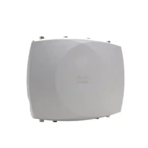
Cisco Wireless CW9177I Wi-Fi 7 Access Point
High-density outdoor wireless built around integrated omnidirectional antennas, tri-band 4×4:4 Wi-Fi 7 radios, up to 12 spatial streams, 10G multigigabit copper, 1/10G SFP/SFP+ fiber capability, GNSS/GPS location services and an IP67-rated hardened enclosure.
Direct answer: what is the Cisco CW9177I?
The Cisco Wireless CW9177I is the integrated-omnidirectional model in Cisco’s Wireless 9177 outdoor Wi-Fi 7 family. It is designed for organizations that need enterprise-grade wireless outside buildings without depending on separate external client antennas. The platform combines three client-serving radio bands—2.4 GHz, 5 GHz and 6 GHz—with a 4×4 uplink/downlink MU-MIMO architecture and four spatial streams per radio. In its tri-band Wi-Fi 7 operating mode, the aggregate physical-layer data-rate capability can reach up to 18 Gbps under ideal channel-width and modulation conditions. That figure is a PHY capability rather than an application-throughput promise, so real network design must still account for client mix, airtime contention, channel plans, regulatory limits, environmental loss, backhaul capacity and protocol overhead.
For UAE enterprise projects, the more important value is architectural headroom. The CW9177I can support high-density modern clients, backward-compatible Wi-Fi generations, 6 GHz spectrum where permitted, 320 MHz channel operation in 6 GHz, Wi-Fi 7 functions such as 4096-QAM, multilink operation, preamble puncturing and uplink/downlink OFDMA, and wired uplinks that are not immediately constrained to 1 Gbps. Its 100M/1G/2.5G/5G/10G multigigabit RJ-45 interface is complemented by a dual-rate 1/10G SFP/SFP+ Ethernet port, giving designers useful copper-versus-fiber choices for campuses, yards and long-distance outdoor runs.
The CW9177I also brings integrated GNSS/GPS, Bluetooth Low Energy/IoT functions, a dedicated scanning radio with Cisco CleanAir Pro capabilities, and a hardened IP67-rated outdoor design. It can fit controller-led Cisco Catalyst architectures or Cisco Meraki cloud-managed designs, which makes it particularly useful for businesses standardizing on common wireless hardware while retaining flexibility in operational model. FourTeck can align wireless design, switching, optics, PoE budgets, controller or cloud licensing and deployment services through FourTeck UAE so the access point is treated as part of an end-to-end network rather than as an isolated radio.
Core CW9177I technical profile
Wi-Fi generation
IEEE 802.11be Wi-Fi 7 with compatibility for earlier 802.11ax, 802.11ac and 802.11n client generations, allowing phased migration rather than forced device replacement.
Radio architecture
Tri-radio design using 2.4 GHz, 5 GHz and 6 GHz, or a design option based on 2.4 GHz plus dual 5 GHz operation where the RF strategy requires it.
Spatial streams
4×4:4 capability on each client-serving radio, providing up to 12 spatial streams across the three-radio architecture.
Integrated antennas
Internal omnidirectional antennas engineered for broad outdoor coverage. Cisco specifies peak gains of 4 dBi at 2.4 GHz and 6 dBi at both 5 GHz and 6 GHz for the CW9177I.
Wired connectivity
One 100M/1G/2.5G/5G/10G multigigabit RJ-45 Ethernet port plus one 1/10G Ethernet SFP/SFP+ port and an RJ-45 management console port.
Outdoor construction
IP67-rated hardened enclosure intended for demanding exterior locations, with a mechanical platform designed around enterprise outdoor use rather than indoor AP placement.
Wi-Fi 7 radio architecture and why it matters
Wi-Fi 7 changes outdoor design because it increases the number of tools available to the RF engineer. The CW9177I supports 4096-QAM for appropriately capable clients operating under favorable signal-to-noise conditions. Higher-order modulation increases the number of bits represented per symbol, but it requires clean RF conditions and strong signal quality. In an outdoor UAE deployment, this means the AP should not be judged only on maximum advertised rate. Mounting height, antenna orientation, obstruction geometry, reflected energy from glass or metal façades, neighboring radio systems, client transmit power and thermal conditions can all change how often high modulation rates are actually sustainable.
The platform also supports multilink operation, one of the defining Wi-Fi 7 capabilities. MLO can allow compatible client and infrastructure implementations to make more intelligent use of multiple links, improving responsiveness, reliability or effective capacity depending on implementation and traffic conditions. This is especially interesting for real-time voice, video, industrial mobility and interactive applications where latency variability matters as much as peak bandwidth. A deployment still needs disciplined RF planning because MLO does not eliminate co-channel interference, poor cell boundaries or overloaded wired infrastructure.
Preamble puncturing provides another useful efficiency mechanism. Wide channels can become difficult to use when a portion of spectrum is affected by interference or incumbent activity. Wi-Fi 7 can selectively avoid an affected subchannel while continuing to make use of the remaining portion of a wider channel, subject to supported operation and regulatory conditions. In practical network engineering, that can improve spectrum utilization compared with an all-or-nothing approach to wide-channel availability. However, a design should still begin with a channel plan matched to density, application demand and local spectrum rules, rather than defaulting every AP to the widest possible channel.
The CW9177I supports uplink and downlink OFDMA and uplink/downlink MU-MIMO. These mechanisms help the infrastructure serve multiple clients more efficiently, particularly when many endpoints exchange smaller flows rather than one device dominating the medium. Target Wake Time can improve power behavior for supported endpoints, while BSS coloring can help networks distinguish overlapping basic service sets and manage reuse more intelligently. Cisco also lists Maximal Ratio Combining and beamforming-related functionality across supported Wi-Fi generations, helping the AP make better use of multiple receive paths and spatial processing.
Channel-width support spans 20 MHz at 2.4 GHz, up to 160 MHz at 5 GHz and up to 320 MHz at 6 GHz for Wi-Fi 7 operation. This matters because each band serves a different planning role. 2.4 GHz offers broad compatibility and propagation but limited clean spectrum; 5 GHz remains a core enterprise capacity band with mature client support; 6 GHz can deliver fresh spectrum and very wide channels for modern clients, but propagation and regulatory behavior differ. The strongest outdoor designs use these bands intentionally rather than treating them as interchangeable.
Integrated omnidirectional antenna system
The defining hardware characteristic of the CW9177I is its internal omnidirectional antenna configuration. Cisco positions this model for wide-area coverage where users and devices can approach from multiple directions and where a single concentrated beam is not the objective. This is distinct from the CW9177D, which uses integrated directional antennas, and the CW9177E, which exposes external antenna connectors for specialized RF patterns. Selecting the I model therefore has a direct effect on site topology: it is best suited to plazas, courtyards, distributed outdoor seating, campus pathways, open logistics zones, recreation areas and exterior spaces that benefit from broad coverage around a mounting point.
Cisco specifies CW9177I peak antenna gains of 4 dBi in 2.4 GHz, 6 dBi in 5 GHz and 6 dBi in 6 GHz. The integrated IoT antenna is specified at 3 dBi and the GNSS antenna at 2 dBi. These values are useful inputs for link-budget thinking, but they are not a replacement for predictive modelling and validation surveys. The realized cell depends on transmit power, local regulatory limits, client antenna performance, mounting elevation, polarization, body loss, vegetation, vehicles, concrete, metal storage racks, containers, tinted glazing and the spatial distribution of users.
Outdoor clients frequently transmit at lower effective power than enterprise APs. That asymmetry can create a misleading design if coverage is planned only by asking how far the AP’s beacon can be detected. A phone may hear the AP at the edge of a courtyard while being unable to return frames at the same quality. FourTeck therefore recommends planning to the weakest important client class and to the application requirement, not merely to a visible SSID. Voice handsets, rugged scanners, tablets, laptops, cameras and IoT devices can all have different radios and roaming behavior.
The internal-antenna format also simplifies mechanical consistency. There are no separate client antenna pigtails to route or third-party antenna patterns to validate for the serving radios. This can reduce deployment complexity and potential installation errors. For projects that need highly focused corridors, point-targeted coverage or very specialized antenna placement, another 9177 variant may be more appropriate. The product decision should therefore follow the RF requirement rather than an assumption that all outdoor access points are functionally equivalent.
Wired uplinks: 10G multigigabit copper and 1/10G fiber flexibility
Multigigabit RJ-45
The CW9177I includes a 100M/1G/2.5G/5G/10G multigigabit Ethernet interface. That range helps during upgrades because existing cabling and switching may not be replaced in one step. The negotiated rate still depends on the switch port, cable plant, distance, quality and configured capabilities, but the AP itself is not limited to a traditional 1 Gigabit uplink.
For dense Wi-Fi 7 usage, designers should evaluate uplink oversubscription, switch backplane capacity and the aggregate behavior of neighboring APs. A high-rate radio connected to a congested access switch does not deliver its architectural potential.
SFP/SFP+ fiber
A dual-rate 1/10G SFP/SFP+ Ethernet port provides a valuable alternative where copper distance, lightning exposure, electromagnetic conditions or campus topology makes fiber attractive. Outdoor networks often span between buildings, yards and remote mounting structures, and fiber can be an important part of a safer, longer-reach architecture when properly engineered.
Optic selection, fiber type, connectorization, enclosure design and grounding strategy must be coordinated with the switching platform and site standards. Treat the AP uplink as part of the full physical network, not simply as a transceiver choice.
Where a customer is modernizing switching at the same time as wireless, FourTeck IT Services UAE can align access-layer switching, VLAN architecture, uplink optics, PoE capacity, segmentation and testing so the wireless upgrade does not uncover avoidable bottlenecks after installation.
Power engineering and PoE planning
Power design deserves the same attention as RF design. Cisco lists 802.3bt, Cisco Universal PoE and 802.3at PoE+ as supported input-power options for the 9177 Series, while 802.3af PoE is identified for configuration or staging with radios off rather than normal radio operation. The exact feature and radio behavior available at a given power level should be validated against the current Cisco power table, software release and intended configuration before final BOM approval.
This has two consequences for UAE deployments. First, the switch must provide not only a compatible PoE standard but also an adequate per-port and total chassis power budget. A switch can have enough multigigabit data ports yet still be unsuitable if the PoE budget cannot support the planned AP count at required power. Second, cable length and conductor quality matter. Voltage drop on long outdoor copper runs can reduce power margin, especially in hot spaces where cable resistance increases. Certified structured cabling, correct gauge, suitable surge protection and installation according to local standards are therefore operational requirements, not cosmetic upgrades.
Power redundancy strategy should reflect the business impact of wireless loss. In a hospitality courtyard, short disruption may be inconvenient. In a port, industrial yard, security perimeter or operational campus, loss of multiple outdoor APs can affect scanners, tablets, voice devices, location services or process workflows. Consider access-switch redundancy, UPS runtime, protected power feeds and distribution boundaries so a single failure does not unnecessarily remove an entire exterior zone.
For staged rollouts, APs can be preconfigured and validated before field deployment, but staging power must not be confused with production power. The installation acceptance checklist should record negotiated Ethernet rate, PoE class or delivered power, radio operational state, controller or cloud registration, firmware level, interface errors and environmental sealing before the unit is handed over.
Outdoor suitability for UAE campuses, logistics and industrial environments
The CW9177I is an outdoor and industrial wireless platform with an IP67-rated enclosure. An IP67 rating indicates strong protection against dust ingress and defined temporary water immersion conditions under the relevant rating framework, but project teams should avoid interpreting any IP code as immunity from every environmental hazard. Proper mounting, cable glands, connector sealing, drip paths, grounding, surge protection and adherence to Cisco installation guidance remain essential.
UAE exterior networks often combine heat, direct solar loading, airborne dust, salt-laden coastal air, condensation transitions between air-conditioned and outdoor spaces, wind and intense seasonal weather. The installation location can therefore be as important as the AP specification. A unit mounted against a dark heat-absorbing surface can experience different thermal stress from one installed with free airflow and appropriate orientation. Cable jackets, conduits, junction boxes, glands and optics must also be suitable for the environmental conditions; the network is only as rugged as its weakest exposed component.
Cisco’s 9177 documentation also highlights tolerance for demanding outdoor conditions and integrated GNSS/GPS. GNSS/GPS capability supports location-oriented functions and regulatory-domain intelligence, including mechanisms related to 6 GHz operation where applicable. Regulatory enablement of bands, channels and transmit power must always follow the country configuration, software release and local rules in force at deployment time. FourTeck does not recommend copying an RF template from another country or assuming that a globally capable AP should use identical 6 GHz parameters everywhere.
Wind loading and mounting integrity also become important at height. Pole diameter, bracket orientation, structural suitability, corrosion resistance, service access and safe working procedures should be agreed before equipment reaches site. For large campus or industrial projects, it is often more cost-effective to standardize mounting details and cable-entry methods than to solve each AP location independently during installation.
A successful outdoor WLAN is therefore the combination of the CW9177I hardware, correct RF design, compliant spectrum configuration, resilient switching and power, environmental workmanship and operational monitoring. The access point is a powerful platform, but it cannot compensate for a poorly engineered supporting infrastructure.
Cisco CleanAir Pro, dedicated scanning and spectrum awareness
The 9177 Series includes a dedicated scanning radio with Cisco CleanAir Pro capability. In enterprise wireless, dedicated spectrum visibility is valuable because the client-serving radios should not have to sacrifice excessive airtime to perform monitoring duties. Continuous awareness of the RF environment can help operations teams identify interference patterns, assess channel quality and improve troubleshooting when users report intermittent performance.
Outdoor interference sources can differ from office interference. Security systems, point-to-point links, neighboring WLANs, venue equipment, temporary event networks, industrial devices and uncontrolled personal hotspots can all alter the spectrum picture over time. A network that performs correctly during a commissioning survey may face a different RF environment during a public event, construction activity or seasonal operational change. The value of spectrum intelligence is therefore ongoing: it supports diagnosis after the initial design has been completed.
CleanAir should be combined with disciplined telemetry. Track channel utilization, noise, retries, client RSSI/SNR distributions, roam events, data rates, DHCP and authentication performance, uplink errors and application symptoms. A high retry rate can be caused by interference, weak client links, cell-size problems or contention, while slow application response may originate beyond the WLAN. Correlating RF, wired and application indicators prevents the common mistake of blaming every user complaint on wireless signal strength.
For managed operations, thresholds should be selected by service class. Guest browsing can tolerate different latency and loss from push-to-talk, voice, video collaboration, point-of-sale or industrial telemetry. FourTeck can help define monitoring baselines and escalation criteria so the CW9177I deployment is operated as a measurable service rather than simply monitored for device up/down status.
Management flexibility: Cisco Catalyst controllers or Meraki cloud
Catalyst-managed architecture
Cisco lists support for Catalyst 9800 Series Wireless Controllers, including physical and virtual controller options, and certain embedded-controller scenarios in Cisco campus architecture. This model suits organizations that prefer an on-premises or controller-centric operational framework with established IOS XE wireless workflows, enterprise policy integration and local control structures.
Controller sizing should consider AP count, client scale, throughput, redundancy, mobility design, software release alignment and feature licensing. The wireless controller should not be selected only because it can technically register the AP.
Meraki cloud-managed architecture
The same hardware family is designed to support Meraki cloud management with the appropriate supported software and licensing. Cloud operations can simplify distributed visibility and configuration for organizations that value centralized SaaS-based management across many sites.
The choice between management models should be made at architectural level. Existing switching, identity systems, change control, operations staffing, telemetry preferences, licensing strategy and security governance all influence which management plane is the better fit.
Cisco’s current 9177 data sheet identifies IOS XE releases 26.2.1 or 26.1.3 or later, or Meraki MR 32.2.x or later, as software baselines for the series at the time of publication. Because software requirements change, project BOMs should always be revalidated before shipment and deployment. Never assume a controller image that supports earlier access points automatically supports a newly released Wi-Fi 7 platform.
Security architecture for enterprise outdoor wireless
The CW9177I supports WPA3 in its Wi-Fi 7 capabilities and WPA2/WPA3 support for compatible earlier-generation operation. Enterprise security, however, requires more than selecting a WPA version. Authentication design, certificate lifecycle, AAA availability, guest onboarding, segmentation, device classification, role-based access and logging should be designed together. Outdoor coverage often reaches beyond physical building boundaries, which increases the importance of minimizing unnecessary signal exposure and enforcing identity-based access controls.
For employee and managed-device networks, 802.1X with a resilient RADIUS or identity-service architecture is generally preferable to broadly shared credentials. Certificate-based authentication can reduce password exposure for managed endpoints when the endpoint ecosystem supports it. Guest wireless should be isolated from internal resources by policy, and Internet-only access should be enforced upstream rather than relying solely on SSID naming conventions. IoT devices may need separate segmentation because their patching cadence and authentication capabilities differ from user devices.
Network segmentation can be implemented using VLANs, policy constructs or fabric-based approaches depending on the Cisco architecture. The design should keep broadcast domains, addressing, DHCP scopes, firewall rules and routing aligned with user and device roles. Outdoor networks can serve cameras, scanners, vehicles, tablets, handhelds, environmental sensors, visitor devices and operational terminals at the same location; combining all of those into one flat subnet creates avoidable risk and troubleshooting complexity.
Management-plane security also matters. Administrative roles should follow least privilege, controller or dashboard access should use strong authentication, configuration changes should be auditable, and software maintenance should be part of a defined lifecycle. Remote sites should have clear procedures for replacing failed APs and securely onboarding replacements without exposing reusable credentials.
Where the WLAN connects to protected enterprise or Internet edge environments, security teams can coordinate the wireless design with firewall policy and secure access services available through Firewall Dubai. The objective is consistent policy from radio association through routed application access, not a separate wireless security island.
RF design methodology for CW9177I projects
A professional CW9177I deployment starts with requirements, not AP quantity. Document the physical areas that require service, the applications used in each area, the number and type of concurrent clients, mobility paths, service-level expectations, security classes and growth horizon. Outdoor density is rarely uniform. A campus entrance may experience short bursts at shift change, while a loading yard may have fewer users but require consistent scanner coverage at all times. Treating both spaces with the same AP spacing rule can create either excessive cost or inadequate capacity.
Next, define the client capability mix. Wi-Fi 7 access points still serve Wi-Fi 6, Wi-Fi 5 and older supported endpoints, and those clients can consume airtime differently. A design dominated by modern laptops and phones can use 6 GHz more aggressively than one dominated by legacy scanners that operate only in 2.4 or 5 GHz. The WLAN should be optimized for the actual endpoint estate rather than the highest capability printed on the AP data sheet.
Predictive modelling should include accurate site dimensions, building materials, outdoor obstacles, container rows, fences, glazing, landscaping and expected mounting locations. Omnidirectional patterns make the CW9177I versatile, but they also require attention to cell overlap. Too little overlap can damage roaming continuity; too much overlap at the same channel can increase co-channel contention. The design goal is not maximum signal everywhere. It is sufficient signal and SNR at the target data rates, with controlled interference and predictable roaming boundaries.
Channel width should be chosen according to capacity and reuse. 320 MHz in 6 GHz can be powerful for high-throughput modern clients, but wide channels consume more spectrum and may reduce reuse options in dense deployments. 160 or 80 MHz may provide a better balance in some locations. In 5 GHz, similar trade-offs apply between throughput per transmission and the number of independent channels. In 2.4 GHz, 20 MHz is normally the practical enterprise choice and Cisco’s Wi-Fi 7 specification for this platform identifies 20 MHz operation in the band.
Transmit power should be coordinated with client capability and neighboring APs. Maximum power can enlarge cells in ways that make roaming sticky and increase same-channel competition. Lower, controlled power can improve reuse in dense areas if enough APs are placed correctly. Conversely, excessive power reduction can create coverage holes or force clients to transmit at inefficient rates. Automated radio-resource management is valuable, but automation works best when the physical AP layout and design constraints are sound.
After installation, perform an active or validation survey under realistic conditions. Confirm RSSI, SNR, channel utilization, roaming, throughput, latency and application behavior at representative points. Test edge cases such as stair exits, gatehouses, parking transitions, covered walkways, loading bays and mobile routes where users actually move. Validate both downlink and uplink behavior because client transmit limitations can reveal problems missed by AP-centric measurements.
Finally, document the RF baseline. Record AP location, mounting height, channel, power, switch port, cable identifier, negotiated Ethernet rate, power delivery, software version and survey results. This baseline becomes invaluable when a future building project, new tenant, temporary event or neighboring radio system changes the environment.
UAE deployment scenarios
Enterprise campuses
Connect courtyards, pedestrian routes, outdoor collaboration zones and building approaches. The omnidirectional antenna pattern is useful when users circulate around the AP rather than remaining in one direction. Fiber uplink capability can simplify long campus paths when copper distance or electrical isolation is a concern.
Logistics and warehousing exteriors
Support handheld scanners, tablets, yard-management terminals and mobile workflows around loading bays or open yards. Site surveys must account for trucks, containers and temporary storage because large metal objects can significantly change RF propagation over the operating day.
Hospitality and resorts
Provide high-capacity coverage around gardens, pool decks, exterior dining and event spaces. Guest experience depends on more than peak speed: stable roaming, captive-portal behavior, Internet gateway capacity and segmentation are critical during busy periods.
Education estates
Extend managed connectivity to outdoor study areas, sports-adjacent zones, walkways and gathering spaces. Dense student-client populations can create rapid demand spikes, so the channel plan and wired aggregation must be sized for concurrent usage, not only average daily load.
Industrial compounds
Serve operational tablets, maintenance teams, telemetry devices and approved IoT endpoints across harsh exterior zones. Fiber uplinks, robust grounding and carefully designed enclosures may be especially valuable where electromagnetic conditions or lightning exposure complicate copper runs.
Public venues and smart environments
Use high-density Wi-Fi 7 capacity for plazas, event approaches and selected public zones. Successful venue deployments require crowd-density modelling, upstream Internet capacity, policy controls and event-day monitoring, not simply higher-power radios.
Capacity planning: turning PHY capability into usable service
Cisco specifies up to 18 Gbps aggregate PHY data rate in the tri-band Wi-Fi 7 configuration under ideal conditions: 4×4 operation with up to 320 MHz on 6 GHz, up to 160 MHz on 5 GHz and 20 MHz on 2.4 GHz. This number demonstrates the radio architecture’s potential, but capacity planning should translate it into realistic service estimates. Wi-Fi is a shared medium. Protocol overhead, contention, retries, management frames, encryption, client capability, channel width, modulation, spatial streams and airtime fairness all reduce application throughput from the theoretical PHY number.
A practical model begins with concurrent clients and application demand. Suppose an outdoor zone has 200 associated devices but only 70 are actively transferring at peak time. Those 70 may include voice devices needing low latency, users streaming video, handhelds exchanging small database transactions and background synchronization from smartphones. The engineer should estimate airtime demand by service type and validate that the channel plan has enough capacity while preserving roaming and retry margins.
Client spatial-stream capability is another limiter. Many mobile devices use fewer spatial streams than the AP can support. The benefit of a 4×4 AP therefore includes multi-client scheduling, receive diversity and infrastructure headroom, but individual client throughput may remain constrained by the endpoint’s own radio. The network should not promise four-stream rates to two-stream devices.
6 GHz can relieve pressure from 5 GHz by moving compatible modern clients into cleaner spectrum, but coverage design must account for propagation. A 6 GHz cell may not match the practical reach of lower-frequency bands under the same mounting and obstruction conditions. This can be beneficial for reuse but may require closer planning to maintain consistent 6 GHz service over a target area. Meanwhile, legacy clients stay on 2.4 or 5 GHz and continue to influence airtime demand there.
Backhaul capacity must be considered at three levels: AP uplink, access switch uplinks and network core or Internet edge. A 10G-capable AP port does not guarantee 10G end-to-end capacity if multiple APs share an undersized switch uplink. Likewise, an outdoor guest network with excellent Wi-Fi can still feel slow if DNS, captive portal, firewall or Internet circuits are congested. Capacity design should follow the user transaction from radio to application.
For high-stakes environments, conduct load testing or pilot validation using representative clients before full deployment. Measure throughput, latency, jitter, packet loss and roam performance across realistic movement paths. The purpose is not to achieve a synthetic benchmark everywhere; it is to prove that business applications meet their defined service targets.
Roaming, mobility and real-time application design
Outdoor enterprise users are often moving. A technician walks between buildings, a logistics operator drives through a yard, hotel staff circulate through guest areas, or students move from interior corridors to external plazas. That means roaming behavior must be designed rather than assumed. The client ultimately decides when to roam, so the network’s role is to create sensible cell boundaries, consistent authentication, predictable channel availability and a policy architecture that does not introduce unnecessary interruption.
Excessively large cells can encourage sticky clients to remain associated with a distant AP even after a better AP becomes available. Excessively small cells can increase roam frequency and coverage holes. Mounting height and transmit power should therefore be calibrated together. Omnidirectional CW9177I cells are convenient for broad areas, but they must overlap with neighboring cells at levels suitable for the actual client type and application.
Voice and other real-time traffic require special attention to latency, jitter and packet loss. A design that passes a speed test can still provide poor voice if roaming pauses or queues become unstable under load. Quality-of-service policy should be consistent across wireless, switching and routed infrastructure, and the WLAN should preserve application markings according to the enterprise policy. Where clients support modern roaming enhancements, enable them according to compatibility testing and security requirements rather than blindly applying every feature.
Mobility validation should follow the user’s path. Test walking and vehicle-speed routes where relevant, observe roam triggers, verify authentication continuity and capture failures at known transition points. Operational teams should retain these baseline traces so future changes can be compared with a known-good state.
IoT, BLE 6.0 and integrated location capabilities
The Cisco 9177 Series integrates a Bluetooth Low Energy 6.0 radio for IoT and location-oriented use cases. In outdoor environments, BLE can support asset visibility, wayfinding and analytics scenarios when paired with the appropriate software architecture, tags, applications and calibrated deployment. The presence of a BLE radio should be viewed as an infrastructure capability rather than a complete asset-tracking solution by itself.
Integrated GNSS/GPS provides location awareness and supports functions associated with regulatory operation and site intelligence. This is particularly relevant to 6 GHz deployments because regulatory frameworks can require location-aware control in certain operating modes. The precise behavior depends on country rules, software support and configuration, so the wireless design should be validated against current UAE requirements and Cisco release documentation before enabling 6 GHz features at scale.
IoT design also requires segmentation and lifecycle planning. BLE tags, sensors and operational devices may remain deployed much longer than employee laptops. Their battery life, firmware, credential model and vendor support should be documented. If location data is collected, the organization should define who can access it, how long it is retained and how it is used. Network technology can create valuable operational insight, but governance remains the customer’s responsibility.
For multi-country organizations extending a common Cisco architecture from the UAE into African operations, FourTeck’s Africa network practice can help align BOM structure, while regulatory settings, power systems, mounting standards and channel plans are localized to each country rather than copied unchanged.
Migration from earlier outdoor Wi-Fi platforms
Cisco positions the 9177 Series as a successor platform for earlier outdoor families such as MR86 and Catalyst 9124-class deployments. Migration should still be engineered as a new RF project rather than a simple one-for-one hardware replacement. Wi-Fi 7 changes radio capabilities, channel options, management-software requirements, power demand and uplink potential. Reusing every old mounting location without analysis can preserve historical RF compromises that no longer match the client population or spectrum strategy.
Start by inventorying existing AP locations, switch ports, cable types, PoE capability, optic types, controller software, licensing and monitoring dependencies. Identify whether each legacy AP solved a coverage problem, a capacity problem or both. Then model the CW9177I at those locations using its actual antenna pattern and target power settings. In some zones, one-for-one replacement may work well. In others, Wi-Fi 7 density requirements or 6 GHz goals may justify changing AP spacing.
Switching is frequently the hidden migration constraint. Older outdoor APs may have been connected at 1 Gbps and powered by earlier PoE standards. The CW9177I can use 10G multigigabit copper and 1/10G SFP/SFP+ paths, so a modernization project should decide which APs genuinely need higher uplink speed and whether the access layer can deliver the required power. Not every AP must necessarily run at the maximum interface rate, but the design should make that choice intentionally.
Software support is equally important. Validate Cisco controller or Meraki release compatibility before a maintenance window. Plan upgrades with rollback procedures, configuration backups and AP staging. If the estate includes multiple generations, confirm that the chosen software release supports all AP models during the coexistence period.
Finally, communicate client expectations. Installing Wi-Fi 7 infrastructure does not turn legacy clients into Wi-Fi 7 clients. Benefits appear progressively as compatible endpoints enter the estate. A good migration therefore protects current service while creating capacity for the next endpoint cycle.
Mechanical planning, cabling and installation quality
The CW9177I enclosure measures approximately 352.2 mm by 270 mm by 76.2 mm without mounting brackets, and Cisco lists the CW9177I access-point weight at approximately 4.11 kg. Those dimensions and weight matter for pole selection, wall loading, bracket handling and work-at-height planning. Installation teams should confirm the correct Cisco mounting hardware, fasteners and structural support for the selected surface.
Cable routing should minimize mechanical stress and water pathways. Outdoor-rated cabling and appropriate gland or sealing methods should be used, with service loops arranged so water does not track directly toward connectors. Copper cabling should follow structured-cabling distance limits and surge-protection practices. Fiber routes should use suitable outdoor or protected cable, correct bend radius and enclosures appropriate to the site.
Labeling is critical in large exterior deployments because APs can be physically distant from their switch rooms. Every cable should map to an AP identifier, switch name, slot and port, and the location should be captured on drawings or GIS/campus maps where appropriate. If an AP fails, the support team should not need a site walk merely to discover which switch port powers it.
Before closure, technicians should inspect seals, torque and connector engagement according to vendor guidance; verify grounding and bonding where required; confirm AP LED and registration state; and check that there are no unexpected interface errors. A photograph of the completed mounting and cable entry is often useful for future support, especially on remote poles or rooftops.
Installation acceptance should include both physical and logical checks. Physical success means the AP is secure and environmentally protected. Logical success means it registers to the correct management plane, receives the intended policy, negotiates expected Ethernet and power characteristics, broadcasts the correct WLANs and passes RF validation.
Operational monitoring and troubleshooting framework
Radio health
Monitor channel utilization, noise, interference classification, retries, transmit power, channel changes and client SNR distributions. Sudden shifts often indicate environmental or neighboring-network changes.
Client experience
Track association failures, authentication failures, DHCP delay, DNS response, roaming events, application latency and throughput. A client that associates successfully can still have a poor end-to-end experience.
Wired health
Monitor negotiated interface speed, CRC or physical errors, drops, PoE events, switch uplink utilization and optic diagnostics. Wireless symptoms can originate from the cable plant or access switch.
Software lifecycle
Maintain approved controller, dashboard and AP software versions. Review Cisco release notes for support, resolved defects, security advisories and required upgrade sequencing before planned changes.
Troubleshooting should use a layered method. First identify scope: one client, one AP, one WLAN, one site or multiple locations. Then isolate the stage of failure: discovery, association, authentication, addressing, DNS, routing, firewall policy or application. RF captures and controller telemetry are most useful when combined with switch and application evidence. Rebooting an AP may temporarily clear a symptom but can erase evidence and does not explain the root cause.
Licensing, ordering and BOM discipline
Cisco ordering for modern wireless platforms is not limited to the AP hardware line item. The final bill of materials can include the access point, applicable subscriptions or licenses, mounting hardware, power accessories where required, optics, patching, surge-protection components, switch upgrades, controller capacity and support coverage. The exact items depend on whether the deployment uses Catalyst controller management or Meraki cloud management, and on the site’s existing infrastructure.
The CW9177I product identifier is the integrated-omnidirectional model. Procurement teams should avoid mixing it with the CW9177D directional model or CW9177E external-antenna model when requesting quotations. Those models share much of the platform architecture but solve different RF problems. A BOM review should therefore verify model suffix, management mode, software requirements, mount type and uplink method for every location class.
Support entitlement should match operational criticality. For a small guest courtyard, the organization may accept different replacement timelines from a mission-critical yard supporting operations. Spares strategy should also reflect site count and geographic spread. A centralized spare can be efficient for clustered Dubai sites but less useful if the estate spans distant emirates or multiple countries.
Before purchase, FourTeck recommends a BOM checkpoint covering quantities, regulatory region, licenses, switch-port availability, PoE power budget, optics, fiber type, patching, mounting surfaces, cabling paths, controller support and delivery staging. This reduces the risk of receiving access points that cannot be commissioned because one dependency was omitted.
Customers requiring coordinated regional sourcing can also use FourTeck Global for multi-site planning while keeping the UAE design aligned with local deployment and support requirements.
When the CW9177I is the right model—and when it is not
Choose the CW9177I when you need broad outdoor coverage around an AP location, want integrated antennas for a cleaner standardized installation, require Wi-Fi 7 capacity, and value 10G copper or 1/10G fiber uplink options. It is particularly suitable where users occupy an area around the mounting point rather than in a narrow directional corridor.
Do not choose the model merely because it is the newest or because it has the highest headline performance in a comparison. If the RF requirement is a focused beam down a corridor, across a specific sector or toward a defined coverage zone, the directional CW9177D may be more appropriate. If the project requires specialized external antennas for unusual geometry, the CW9177E may be the better engineering choice. If the environment is indoors, a purpose-built indoor Wi-Fi 7 AP can provide a more appropriate mechanical and antenna profile.
Likewise, a 10G-capable uplink should not force an unnecessary switch replacement if measured demand is modest and the architecture has a planned migration path. The interface capability creates headroom; the deployment should still balance cost, performance and lifecycle. Conversely, deploying a premium Wi-Fi 7 AP on an overloaded 1G access layer with insufficient PoE and congested upstream links can waste the investment.
The correct product decision is therefore the intersection of RF pattern, client density, application requirement, management architecture, switching capability, environmental exposure and lifecycle plan. FourTeck’s role is to turn those inputs into a coherent design and BOM rather than treating the access point as a stand-alone catalog item.
Detailed UAE sizing methodology
A reliable AP count cannot be calculated from floor area alone. Start by dividing the outdoor environment into usage zones. A 5,000-square-meter yard with 30 scanners requires a different design from a 5,000-square-meter event lawn holding 1,500 guests. For each zone, record expected concurrent devices, device types, applications, target minimum data rate, roaming requirement and whether 6 GHz is a core requirement or an additional capacity layer.
Next, estimate capacity. For each application class, approximate average and peak throughput and consider transaction behavior. Voice uses modest bandwidth but is sensitive to jitter and loss. Video can create sustained throughput. Cloud synchronization can create bursts. Scanners may use very little bandwidth but require continuous low-latency connectivity. Multiply by concurrent active devices, then add margin for growth and protocol overhead. This yields a service target that can be compared with expected per-radio capacity under realistic channel widths and client capabilities.
Then model coverage. Use a predictive tool with site geometry and material attenuation. Place APs where mounting and cabling are feasible, then evaluate target signal levels for the weakest important client. Pay special attention to transitions behind concrete structures, metal enclosures, landscaping and parked vehicles. For outdoor courtyards surrounded by reflective glass and concrete, multipath may be significant; for open fields, path loss and mounting height dominate.
Evaluate channel reuse. In 6 GHz, wide channels can provide excellent performance, but using 320 MHz everywhere can reduce the number of non-overlapping channel opportunities depending on the regulatory plan. Dense designs may benefit from narrower channels. In 5 GHz, 80 MHz or 40 MHz can sometimes serve more users overall than 160 MHz because more cells can reuse spectrum with lower co-channel contention. Channel width is therefore a capacity-planning variable, not a fixed indicator of quality.
Check power and backhaul. Determine whether each AP uses copper or fiber. For copper, verify route length, cable category, outdoor protection and PoE delivery. For fiber, specify optic type, fiber strand, termination and a suitable power source for the AP. Confirm switch-port count, PoE budget, switch uplink bandwidth and redundancy. A design can be perfect in RF software and still fail during installation if the chosen poles have no viable power or data path.
Conduct a pre-installation survey where practical. Predictive maps do not always reveal hidden metal structures, newly built walls, temporary cabins or sources of interference. Confirm mounting heights, line of sight, safe access and cable pathways. Photograph critical locations and mark each proposed AP on the implementation drawing.
After deployment, validate under load. Check 2.4, 5 and 6 GHz behavior with representative devices, not just a single engineering laptop. Walk roaming paths, measure application latency, check authentication and DHCP timing, and test peak areas. Review controller or dashboard telemetry for retries and channel utilization. If results differ from the model, adjust power, channels or placement based on evidence.
Finally, preserve documentation for operations. A sizing study should produce an AP map, switch-port map, RF plan, IP/VLAN plan, licensing record, software baseline, survey results and spare strategy. These documents turn the network from a one-time installation into a maintainable enterprise service.
Wi-Fi 7 feature interpretation for technical buyers
4096-QAM: increases modulation density compared with 1024-QAM, but only when signal quality is strong enough. It improves peak efficiency close to the AP or in favorable RF conditions; it should not be used as a coverage guarantee.
320 MHz channels: available in 6 GHz for Wi-Fi 7 on the platform, providing very wide bandwidth for compatible clients. The design trade-off is reduced channel reuse and stronger dependence on 6 GHz coverage, so dense enterprise networks may deliberately choose narrower channels.
Multilink operation: allows compatible Wi-Fi 7 systems to coordinate multiple links. Potential benefits include improved responsiveness, resilience and throughput efficiency, but actual behavior depends on client and network implementation.
Preamble puncturing: can allow use of a broad channel even when part of that spectrum is impaired or unavailable, improving flexibility compared with abandoning the entire wide channel.
OFDMA: improves efficiency when serving multiple clients with different traffic demands by dividing channel resources into smaller units. This is useful in dense networks with many simultaneous flows.
MU-MIMO: enables multi-user spatial transmission under supported conditions. The CW9177I’s 4×4 radio architecture provides significant infrastructure capability, but realized gains depend on client support, channel state and scheduler decisions.
Target Wake Time: can reduce unnecessary client wake activity for supported devices and traffic patterns, which can be valuable for battery-operated endpoints.
BSS coloring: helps devices distinguish overlapping wireless networks and can improve spectrum reuse behavior where multiple cells share channel space. It supports good design; it does not replace proper channel planning.
Common design mistakes to avoid
One-for-one replacement without survey
A new radio platform can change cell behavior, channel strategy and capacity. Reusing old AP locations without validation may preserve legacy design problems.
Maximum channel width everywhere
Wider channels are not always better. Dense networks often gain from additional channel reuse and lower contention when channel width is selected deliberately.
Ignoring client transmit power
The AP may be heard farther than a mobile device can reply. Plan to the weakest important endpoint and verify uplink performance during survey.
Underestimating switch PoE
A switch with enough Ethernet ports can still fail the project if the chassis power budget cannot supply all APs at the required operating level.
Treating IP67 as complete installation protection
Outdoor reliability also depends on glands, cables, grounding, surge design, mounting workmanship and environmental suitability of every exposed component.
Benchmarking only with one laptop
Enterprise WLANs serve a diverse client estate. Validate scanners, phones, tablets and IoT devices that represent real operational risk.
Implementation lifecycle from design to handover
1. Discovery: identify sites, user groups, device mix, applications, security requirements, operational hours, existing controllers, switches, cabling and Internet/WAN dependencies. Capture the business reason for the upgrade so design decisions can be measured against outcomes.
2. RF design: create predictive models, define target signal/SNR, decide band strategy, channel width, mounting points and expected AP quantities. Select CW9177I only where omnidirectional coverage matches the environment.
3. Infrastructure assessment: audit PoE, mGig ports, fiber options, switch capacity, controller compatibility, licensing, IP addressing, VLANs, DHCP and firewall policy. Identify long-lead items before the purchase order.
4. BOM validation: confirm AP model, regulatory region, mounts, optics, patching, power accessories, support and licenses. Verify that software versions support the 9177 platform and all coexistence AP models.
5. Staging: upgrade management systems where required, build WLAN profiles and policies, onboard sample APs, validate licensing and test representative clients before field work.
6. Physical installation: install mounts, cable and grounding according to approved drawings and vendor guidance. Label every path, seal outdoor entries and capture installation evidence.
7. Commissioning: verify AP registration, software, radio state, SSIDs, policy, negotiated Ethernet speed, PoE delivery, VLAN reachability, DHCP, DNS and Internet/application access.
8. RF validation: perform surveys and mobility tests, assess channel utilization and retries, test high-density zones and verify service on multiple client classes.
9. Handover: provide as-built AP maps, switch-port records, configuration backups, license records, software baseline, test results and escalation procedures.
10. Optimization: review telemetry after real users return to the environment. The first week of production can reveal density patterns and interference conditions that no predeployment survey can perfectly reproduce.
Decision recap for UAE buyers
Choose CW9177I for
Broad outdoor coverage, integrated omnidirectional antennas, high-density Wi-Fi 7, tri-band 4×4:4 architecture, up to 12 spatial streams and organizations that want modern capacity without external serving antennas.
Validate before ordering
Controller or Meraki software, subscriptions, mounting, PoE delivery, switch mGig capability, fiber optics, local 6 GHz rules, AP count and whether omnidirectional coverage suits each physical zone.
Do not size from
Headline PHY rate, square meters alone or legacy AP quantities. Size from client density, airtime, coverage targets, client capabilities, application SLAs, RF reuse, power and end-to-end wired capacity.
Operational advantage
Dedicated scanning, CleanAir Pro, GNSS/GPS, BLE/IoT integration and management flexibility create a platform that can be monitored and evolved as client populations and spectrum use change.
Quotation input checklist
For an accurate Cisco CW9177I UAE quotation and design recommendation, prepare the following information. Providing these inputs reduces assumptions and helps the BOM reflect the real installation rather than a generic per-unit price.
Emirate, site type, outdoor area, drawings, mounting heights, obstacles, expected user zones and any existing survey data.
Expected concurrent users, device types, Wi-Fi generations, critical scanners or IoT devices, and mobility paths.
Guest access, voice, video, operational apps, point-of-sale, telemetry, collaboration, cameras or other latency-sensitive services.
Controller model, software version, Meraki organization if applicable, current licenses, AP generations and identity services.
Switch models, available mGig ports, PoE standards, remaining power budget, uplink capacity and UPS coverage.
Copper category and run lengths, fiber type, available strands, SFP/SFP+ standards, outdoor enclosures and surge requirements.
802.1X, guest access, VLANs, firewall zones, device roles, Internet breakout and logging requirements.
Required quantity, target deployment date, working-hour constraints, access permits, work-at-height needs, spare policy and support expectation.
FourTeck consultation for Cisco CW9177I deployments
The Cisco Wireless CW9177I gives UAE organizations a strong outdoor Wi-Fi 7 foundation, but the result depends on how well radio design, power, switching, security and operations are integrated. FourTeck can support discovery, BOM validation, predictive RF planning, switching and PoE assessment, controller or Meraki readiness, installation coordination, commissioning and post-deployment validation.
For a new campus, start with drawings and client-density assumptions. For a replacement project, provide the current AP map, controller details and switch inventory. For a performance problem, provide telemetry, survey results and the specific application symptoms. Each path leads to a different technical engagement, and that distinction prevents unnecessary hardware changes.
The recommended next step is to define the coverage zones, concurrent client count, management model and available wired infrastructure. From there, FourTeck can determine whether the CW9177I is the correct antenna variant, estimate quantities, identify switching or licensing dependencies and prepare an implementation-ready proposal for UAE deployment.

Reviews
There are no reviews yet.