
Enterprise Access Switching for Dubai & UAE
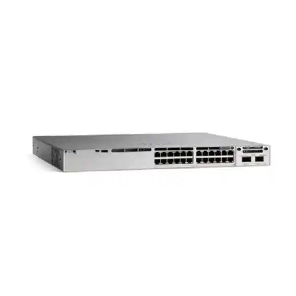
Cisco Catalyst C9300LM-24U-4Y Network Switch
A shallow-depth, stackable 24-port Cisco UPOE access switch with four fixed 25 Gigabit SFP28 uplinks, Cisco UADP 2.0 forwarding silicon, StackWise-320 resilience and Cisco IOS XE software for secure, programmable enterprise campus and branch networks.
4 × 25G SFP28 Uplinks
StackWise-320
UADP 2.0 ASIC
Direct answer: what is the Cisco C9300LM-24U-4Y?
The Cisco Catalyst C9300LM-24U-4Y is the 24-port UPOE model in Cisco’s shallow-depth Catalyst 9300LM family. It is designed for enterprise access-layer deployments that need full-featured Catalyst switching but cannot accommodate the deeper chassis dimensions common in traditional campus closets. The switch provides twenty-four copper Ethernet access ports operating at 10 Mbps, 100 Mbps or 1 Gbps, with Cisco Universal Power over Ethernet support for powered endpoints. Uplink connectivity is delivered through four fixed SFP28 interfaces capable of 25 Gigabit Ethernet, creating significantly more northbound bandwidth than fixed-uplink access switches limited to 1G or 10G uplinks.
For Dubai offices, distributed UAE branches, retail sites, hospitality environments, education facilities, healthcare networks and industrial administration buildings, the model addresses a common design problem: high-density powered edge devices combined with limited rack depth and a growing requirement for faster aggregation links. The C9300LM-24U-4Y uses Cisco’s UADP 2.0 application-specific integrated circuit to provide hardware-based forwarding and policy processing. It supports Cisco StackWise-320, allowing compatible fixed-uplink Catalyst 9300L and 9300LM switches at the same license level to be formed into a resilient logical stack when the required stacking accessories are installed.
The current Cisco specification lists 248 Gbps of standalone switching capacity and 184.51 million packets per second of forwarding performance. When stacking is included in the system calculation, Cisco lists 568 Gbps of switching capacity and 422.59 Mpps of forwarding rate. The standard 600W AC power supply provides 420W of available PoE power, with higher power-supply and secondary-power configurations available for designs that require additional PoE headroom or power redundancy. This combination makes the switch suitable for IP telephony, enterprise Wi-Fi access points, surveillance cameras, building systems and standard user access while retaining 25G-ready aggregation connectivity.
Key hardware specification summary
Access ports
24 × copper 10/100/1000 Mbps Ethernet ports with Cisco UPOE for data and powered-device connectivity.
Fixed uplinks
4 × 25G SFP28 fiber uplink interfaces for high-bandwidth distribution or core connectivity without an optional uplink module.
Forwarding silicon
Cisco UADP 2.0 ASIC architecture for hardware-accelerated enterprise switching, policy and telemetry functions.
Stacking
Cisco StackWise-320, supporting up to eight compatible switches in a stack when the correct stack kit and cables are used.
Power
Default 600W AC power supply with 420W available PoE budget; optional power combinations can increase available powered-device capacity.
Physical profile
1RU class shallow-depth chassis, approximately 1.73 × 17.50 × 13.03 inches chassis-only, with a listed weight of about 11.5 lb.
Why the C9300LM architecture matters in real network design
Enterprise access switching is no longer a simple calculation of user ports. A modern switch has to supply power, enforce identity policy, support segmentation, transport telemetry, survive link or device failures, connect increasingly fast wireless systems and integrate into automation platforms. The C9300LM-24U-4Y is positioned for this richer access-layer role while reducing the depth requirement of the chassis. That physical characteristic is especially useful in branch cabinets, wall-mounted network enclosures, older office fit-outs and telecommunications spaces where a deep full-size switch can interfere with cabling bend radius, cabinet doors, UPS equipment or passive patching.
Its UADP 2.0 ASIC is important because forwarding and many policy operations are handled in dedicated switching silicon rather than being treated as general-purpose software tasks. That gives the platform the predictable behavior expected from a Catalyst enterprise access design. The four 25G SFP28 fixed uplinks also change how architects can build oversubscription ratios. A 24-port Gigabit switch has a theoretical aggregate of 24 Gbps of user-facing line rate in one direction. Four 25G uplinks provide substantial northbound capacity, allowing designs to use multiple active uplinks, port-channel architectures, diverse upstream switches, or staged migration from lower-speed optics to 25G where supported.
Because the uplinks are fixed, procurement is also simpler than with modular-uplink models: the switch SKU already defines the physical uplink interface family. The trade-off is that the uplink form factor cannot be replaced with a different network module later. For many standardized branch and compact-campus designs, that is beneficial because bill-of-materials consistency, rack planning and spares management become easier. FourTeck can align compatible optics, fiber types, patch leads and upstream switch interfaces around the chosen topology, avoiding a common deployment problem in which the switch arrives before the transceiver and cabling plan has been validated.
24-port UPOE access layer: planning power as carefully as bandwidth
The C9300LM-24U-4Y provides twenty-four Universal Power over Ethernet capable access ports. UPOE is valuable when an organization wants to converge endpoint data and power over structured copper cabling, reducing the requirement for separate local electrical outlets at every device. Typical loads include IP phones, wireless access points, surveillance cameras, badge readers, small room systems, IoT gateways and selected compact edge devices. The switch’s power design should be sized against the actual powered-device inventory rather than simply assuming that every endpoint draws its maximum negotiated wattage continuously.
With the default 600W AC supply, Cisco lists 420W of available PoE power for the C9300LM-24U-4Y. A practical design begins by listing every powered endpoint, its class or maximum draw, expected normal draw, startup behavior and criticality. Twenty-four endpoints averaging 12W consume 288W, leaving comfortable headroom. A mixed deployment containing high-power access points and cameras can rise much faster, so room-by-room or port-by-port power planning is essential. Higher-capacity primary or secondary power configurations can raise the available PoE envelope, but the exact configuration should be selected with power redundancy objectives, input-circuit capacity and thermal planning in mind.
UPOE also changes operational thinking. When a powered device becomes unreachable, a network administrator may be able to reset its power remotely from the switch rather than sending onsite staff to disconnect a cable. Maintenance windows can be coordinated by port. Critical devices can be mapped to particular switch members in a stack so failure-domain planning is explicit. For camera or voice systems, the switch and any upstream UPS must be sized together because maintaining Ethernet during a mains outage is not useful if the PoE budget collapses when the UPS is undersized.
In UAE deployments, power and cooling design should account for cabinet location, ambient temperature, dust control, UPS autonomy and the fact that many branch racks combine switching, firewall, servers, NVRs and telecom equipment in a constrained enclosure. FourTeck’s UAE IT services team can assist with structured deployment planning where switching, PoE endpoints, UPS capacity, rack space and network services need to be coordinated rather than purchased as isolated components.
Four fixed 25G SFP28 uplinks: a major advantage for compact access designs
The four 25G SFP28 uplinks are one of the defining technical reasons to select the C9300LM-24U-4Y. Many compact fixed-uplink access switches offer only 1G or 10G northbound connectivity. That can be sufficient for traditional user access, but it becomes restrictive when a branch or building distributes large files, high-resolution video, virtual desktop traffic, backups, wireless client traffic or east-west application flows through a small number of uplinks. A 25G uplink can provide substantially more aggregation headroom while retaining the compact SFP28 optical form factor.
The correct transceiver choice depends on distance, fiber type, upstream interface and optical budget. Short in-building links may use one optical strategy, while longer campus runs may require another. Existing multimode or single-mode plant must be surveyed before optics are ordered. Organizations should not assume that a connector that physically fits automatically creates a supported link. Transceiver speed, wavelength, fiber category, connector polish, patching, attenuation and upstream switch support all have to align. Where existing aggregation operates at 10G, migration should be planned around Cisco-supported interface behavior and optics rather than improvised adapter combinations.
From a topology perspective, four uplinks allow several useful patterns. Two links can form a port channel to one logical upstream system while two remain available for redundancy or separate services. A stack can distribute uplink connections across members to reduce the impact of a single physical switch failure. In dual-distribution designs, links can be spread across independent upstream nodes according to the selected Layer 2 or Layer 3 architecture. The right choice depends on whether the access layer is routed or switched, how default gateways are placed, what convergence targets are required and whether the network uses traditional campus design or Cisco fabric technologies.
For sites building security zones around high-speed access, the upstream network and firewall architecture must also be sized appropriately. Sending four 25G-capable uplinks into an aggregation layer does not create end-to-end 25G application throughput if the firewall, WAN service, server interface or storage path is constrained. FourTeck’s Firewall Dubai specialists can coordinate switching and perimeter-security sizing so uplink capacity, inspection performance and routed design are evaluated as one system.
Performance: 248 Gbps switching and wire-speed access behavior
Cisco lists the standalone switching capacity of the C9300LM-24U-4Y at 248 Gbps and its forwarding rate at 184.51 Mpps using 64-byte IPv4 packets. With stacking included in Cisco’s platform calculation, the listed figures rise to 568 Gbps switching capacity and 422.59 Mpps forwarding rate. Cisco describes the Catalyst 9300 family as providing wire-speed nonblocking performance for IPv4 and IPv6. These numbers provide a hardware reference point, but real application performance is still determined by topology, policy, traffic mix, endpoint capabilities and upstream bottlenecks.
Switching capacity represents the volume of data the switching fabric can process. Forwarding rate measures packets per second and becomes particularly relevant with small packets, where packet-processing demand can rise sharply even if total bandwidth is not saturated. Enterprise traffic is rarely uniform: a user access switch may simultaneously carry large backup frames, latency-sensitive voice packets, wireless control traffic, short application transactions and multicast video. The platform’s value therefore comes not only from a peak bandwidth number but from the combination of switching capacity, queues, QoS, hardware policy enforcement and operational visibility.
The C9300LM-24U-4Y supports jumbo frames up to the Catalyst 9300 family value of 9198 bytes, which can be useful in selected storage, virtualization and data-transfer scenarios. Jumbo-frame deployment should be end-to-end consistent; enabling a larger MTU on one access switch does not help if an intermediate firewall, router, WAN circuit or server interface remains at a lower maximum. MTU inconsistency can create hard-to-diagnose application behavior, particularly when path MTU discovery is blocked or asymmetric routes exist.
For buyers comparing model classes, the performance figures should be viewed alongside the 24-port 1G access profile. If many endpoints require 2.5G, 5G or 10G copper, a multigigabit Catalyst model may be more appropriate. If endpoints are primarily 1G but the aggregation layer needs substantial uplink capacity, this 24U-4Y configuration is especially compelling because it concentrates investment in resilient high-speed uplinks without forcing multigigabit copper ports that may not be used.
StackWise-320 resiliency and scale
Cisco StackWise-320 is supported on the C9300LM platform and provides up to 320 Gbps of stacking bandwidth. Cisco documentation indicates that up to eight compatible switches can be configured in a StackWise-320 system using the required rear stack adapters and dedicated stack cables. For the 9300LM family, the appropriate stack kit must be included in the bill of materials because stacking hardware is not simply implied by the front-panel Ethernet interfaces.
A physical stack allows multiple switches to operate as a coordinated system, simplifying management and enabling cross-stack design techniques. This can reduce the number of independently managed switch control points in a wiring closet and support link aggregation designs that span physical members. The stack can also improve maintenance flexibility: access ports, uplinks and powered devices can be distributed across members so the effect of a single hardware fault is reduced. Redundancy is not automatic, however. A well-designed stack also requires diverse uplinks, balanced power, documented stack-cable topology, compatible software, matching licensing expectations and a clear process for member replacement.
Cisco states that C9300L and C9300LM platforms can stack with compatible models when license levels and platform rules are observed. This is useful for sites that need a mixture of port counts or capabilities, but every mixed-stack design should be validated before purchase. Engineers should confirm the exact model combination, IOS XE release, stack kit generation, cable lengths and licensing alignment. The default stack cable length is suited to adjacent rack positions; longer supported lengths may be needed when cabinet layout prevents direct adjacency.
Stacking is especially attractive in UAE branch or building deployments where the organization wants a standardized two-switch or three-switch access block. A pair of C9300LM-24U-4Y switches can provide additional port and PoE capacity while allowing uplinks to be divided across members. For larger closets, multiple members can be added while keeping a consistent operational model. The design should still account for failure domains: a single stack is one logical system, so critical environments may prefer multiple stacks or dual access blocks rather than concentrating every endpoint into one administrative unit.
Cisco IOS XE: programmable enterprise operations
The C9300LM-24U-4Y runs Cisco IOS XE, the software foundation used across much of the Catalyst 9000 portfolio. For network operations teams, the significance is broader than traditional command-line configuration. IOS XE exposes model-driven interfaces and supports automation through technologies such as NETCONF, RESTCONF and gNMI using YANG data models. This allows switch configuration and telemetry to be integrated into modern network automation frameworks, controller platforms and custom operational tooling.
Automated provisioning is particularly valuable in distributed organizations. A company deploying standardized branches across Dubai, Abu Dhabi, Sharjah or other Emirates can define a baseline for VLANs, routing, authentication, QoS, logging and management, then automate large parts of first-time configuration. Cisco supports deployment mechanisms such as Plug and Play and zero-touch provisioning workflows. Automation reduces configuration drift and can shorten rollout cycles, but it increases the importance of source-controlled templates, role-based access, test environments and change validation. A bad template can scale an error just as efficiently as a good template scales a correct design.
Model-driven telemetry enables the switch to stream selected operational data to collectors based on subscriptions. Compared with periodic polling alone, streaming telemetry can provide more granular visibility into interface state, counters and other supported operational data. For large estates, this helps engineers identify patterns such as recurring uplink congestion, error growth, flapping clients or PoE instability before users escalate incidents. The actual monitoring architecture may use Cisco Catalyst Center, third-party platforms or custom observability stacks, depending on licensing and operational preferences.
IOS XE also supports software patching mechanisms for selected fixes between regular maintenance releases. Change policy remains essential: enterprises should track Cisco recommended releases, published security advisories, hardware support matrices and application dependencies. Production networks should avoid arbitrary upgrades simply because a newer version exists. A lifecycle plan should define approved code, maintenance windows, rollback procedures, stack upgrade behavior and validation steps for routing, authentication, phone services, wireless dependencies and monitoring after each change.
Security capabilities from the access layer
The access switch is the first infrastructure device encountered by most wired endpoints, so it is a strategic control point for security. The Catalyst 9300 family supports features that help organizations authenticate devices and users, segment traffic, protect infrastructure links and increase visibility. Which specific functions are available in a deployment depends on the selected Network Essentials or Network Advantage base license, any required subscription, software release and the wider Cisco architecture.
Cisco Trust Anchor technology provides a hardware-rooted basis for platform authenticity and secure boot processes. Signed software images and secure boot mechanisms help protect the integrity of code loaded by the switch. These controls are important because a compromised infrastructure device can undermine segmentation, redirect traffic or create persistent unauthorized access. Hardware trust does not remove the need for operational controls such as secure credential management, restricted management networks, AAA, logging and software maintenance, but it strengthens the foundation on which those controls depend.
The Catalyst 9300 family supports IEEE 802.1AE MACsec with AES-128 and AES-256 options for supported link-encryption use cases. MACsec can protect Ethernet frames on links between capable devices, reducing exposure to traffic interception on physical Layer 2 paths. It should be designed deliberately because key management, peer support, topology and performance considerations matter. Organizations that need encrypted site-to-site routing should distinguish MACsec from IPsec; the platform family has different encryption capabilities by model, and line-rate IPsec features highlighted for Catalyst 9300X should not be assumed to apply identically to the C9300LM.
The broader Catalyst 9300 security portfolio also includes Flexible NetFlow and application-visibility functions that can contribute to incident detection and capacity analysis. Flow records help answer practical questions: which endpoints are generating unexpected traffic, which applications dominate a WAN path, and whether a policy change altered behavior. When combined with identity systems, firewalls and network analytics, access-layer telemetry can materially improve threat-hunting context. For perimeter and segmentation design, FourTeck can integrate the switch into a wider security stack rather than treating it as an isolated Layer 2 device.
Security controls should be mapped to business zones. Corporate users, guest devices, voice endpoints, cameras, building systems and unmanaged IoT devices often have very different trust requirements. The switch can participate in VLAN, ACL, identity and policy-based segmentation approaches, while northbound firewalls enforce inter-zone inspection where required. The result is a layered design in which the C9300LM-24U-4Y provides a controlled access edge and the firewall, routing and identity platforms provide complementary enforcement.
Segmentation, SD-Access and policy-based campus design
Traditional enterprise networks often segment users by VLAN and subnet, then rely on access lists or firewalls to control communication. That model remains valid for many sites, but it becomes operationally complex as the number of device classes and locations grows. Cisco SD-Access introduces policy-based automation and fabric segmentation across wired and wireless infrastructure. Within a properly licensed and designed Cisco environment, Catalyst 9300 switches can participate in this architecture so access policy follows user or device identity rather than being tied entirely to physical switch ports and static IP addressing.
The decision to adopt SD-Access should be architectural rather than product-driven. A single C9300LM switch can operate successfully in a conventional campus design using VLANs, spanning tree, EtherChannel and Layer 3 routing. Organizations should not add a fabric simply because the switch supports one. SD-Access becomes more compelling when the estate is large, policy requirements are complex, wireless and wired access need consistent segmentation, and the operations team will use Cisco Catalyst Center for automation and assurance.
Network Advantage is commonly associated with more advanced capabilities than Network Essentials, so license selection should be part of the design phase. Cisco offers C9300LM-24U-4Y-E and C9300LM-24U-4Y-A ordering variants corresponding to Network Essentials and Network Advantage. Cisco’s licensing model combines perpetual network entitlements with term-based Cisco Catalyst and Cisco DNA software subscriptions for specified ordering models. Current ordering rules and subscription terms should be validated in the quote because Cisco licensing evolves over time and affects both feature availability and support entitlement.
For Dubai organizations with mixed legacy and modern environments, migration can be phased. The C9300LM can first replace aging access switches using familiar VLAN and routing methods, then be incorporated into broader automation and assurance later if business requirements justify the investment. This protects operational continuity while preserving a path toward more centralized policy. The key is to create a clean baseline: standardized naming, documented address plans, disciplined VLAN use, consistent AAA, accurate inventory and supported software releases.
QoS for voice, video, wireless and business applications
An enterprise access switch routinely carries applications with conflicting requirements. Bulk file transfers want bandwidth; voice needs low latency and low jitter; interactive video is sensitive to loss; backups can tolerate delay but consume large bursts; and guest traffic should not starve business applications. Catalyst 9300 platforms provide QoS capabilities for classification, marking, scheduling and congestion management so traffic can be treated according to business importance rather than first-come, first-served behavior alone.
Cisco documentation identifies support for Layer 2 Class of Service markings, Layer 3 DSCP classification, committed-rate mechanisms and multiple egress queues per port. The correct policy is environment-specific. Trusting DSCP from every connected endpoint is usually inappropriate because unmanaged devices can mark traffic incorrectly. A common approach is to establish trust boundaries around managed phones, wireless infrastructure or approved systems, then remark untrusted traffic at the access edge. The switch should classify only what the organization has decided is business critical.
QoS also needs end-to-end continuity. Marking voice on the C9300LM is useful only if the upstream distribution switch, firewall, WAN edge and carrier service preserve or intentionally translate those classes. When traffic crosses the Internet, the organization generally cannot expect deterministic QoS treatment. For private WAN, SD-WAN or MPLS services, carrier class models and shaping rates must be aligned with the LAN policy. Congestion often occurs not on the Gigabit access port but at a slower WAN edge, so bandwidth hierarchies should reflect real bottlenecks.
For unified communications deployments, switch power and QoS should be designed together. IP phones may receive power from the C9300LM while voice signaling and media receive priority treatment. Wireless access points may also draw significant PoE while tunneling or bridging high volumes of client traffic. FourTeck can coordinate switching with IP telephony and wireless infrastructure through the broader FourTeck UAE technology portfolio, helping ensure that power budgets, VLANs, DHCP options, QoS and uplink capacity are consistent across the solution.
Flexible NetFlow and operational visibility
Network troubleshooting improves dramatically when engineers can see not just interface utilization but the traffic conversations using that bandwidth. Cisco Flexible NetFlow provides flow-level visibility that can be exported to compatible collectors for analysis. On Catalyst 9300 Gigabit Ethernet models, Cisco lists support for up to 64,000 Flexible NetFlow entries. This scale can help branch and campus teams identify application patterns, unusual communication, top talkers and changes in usage over time.
Flow telemetry is most valuable when questions are defined before data is collected. If the objective is WAN capacity planning, records should make source, destination, application and byte counts easy to analyze. If the objective is security visibility, the team may care about unexpected east-west connections, communication to rare destinations or sudden changes in device behavior. If the objective is application troubleshooting, latency data from other systems may need to be correlated with switch flow records. NetFlow is therefore one layer in an observability strategy, not a complete monitoring platform by itself.
The Catalyst 9300 family also supports NBAR2 application recognition capabilities. Cisco describes a broad library of predefined application signatures that can help classify traffic beyond simple port numbers. This is useful because many modern applications use dynamic ports or share common encrypted transport. Application recognition can improve policy and reporting, but encrypted traffic reduces payload visibility, and cloud applications change frequently. Monitoring systems should therefore combine application classification with DNS, identity, endpoint, firewall and SaaS telemetry where appropriate.
For UAE enterprises operating multiple branches, central flow collection can reveal which sites are approaching capacity, which users are consuming backup bandwidth during business hours, and whether a newly deployed cloud application has changed traffic patterns. That evidence supports better upgrade decisions than relying on anecdotal reports of a “slow network.” The C9300LM-24U-4Y provides the access-layer instrumentation; the operations process determines whether the telemetry becomes actionable information.
High availability beyond stacking
Stacking is only one part of resilient campus design. A reliable C9300LM deployment should consider uplink diversity, gateway placement, spanning-tree behavior, routing protocol convergence, power redundancy, patching paths and the failure impact of upstream devices. Cisco Catalyst 9300 platforms support enterprise resiliency mechanisms including rapid spanning-tree variants, Multiple Spanning Tree, EtherChannel-related designs and, in appropriate architectures, Non-Stop Forwarding and Stateful Switchover capabilities within supported stack configurations.
The most effective resilience pattern depends on the network layer at which redundancy is implemented. A Layer 2 access switch connected to two upstream distribution switches must avoid loops while still converging quickly. A routed-access design may use Layer 3 links and routing protocols to eliminate some spanning-tree dependencies. A fabric-based design handles redundancy differently again. Engineers should avoid mixing patterns without understanding control-plane interaction. For example, adding extra physical uplinks does not automatically improve reliability if they create an unsupported topology or remain blocked without providing the intended failover behavior.
Power deserves equal attention. The default C9300LM-24U-4Y power configuration provides the documented 420W PoE budget. Cisco also lists optional configurations that can increase available PoE and provide additional supply capacity. Where switch uptime is critical, a secondary power supply and independent electrical feeds may be appropriate. Those feeds should ideally terminate on separate UPS or power-distribution paths if the facility design supports it. Two power supplies connected to the same single failed circuit do not provide true electrical diversity.
Finally, operational resilience requires spares and recovery procedures. Teams should keep a current configuration backup, document the stack member roles and serials, record optics, store approved IOS XE images, maintain console-access procedures and understand the replacement process for a failed member. Hardware redundancy without documentation can still produce long outages when staff do not know how the system was intended to fail over.
Physical design: shallow depth for constrained racks
The “LM” variant is especially notable for physical compactness. Cisco lists the C9300LM-24U-4Y chassis dimensions at approximately 1.73 inches high by 17.50 inches wide by 13.03 inches deep before accounting for the exact power-supply projection and cable bend space. The listed weight is approximately 11.5 lb. This makes the model attractive where network cabinets are shallower than standard data-center racks or where rear clearance is consumed by patch panels, PDUs, UPS equipment and building cabling.
A shallow switch does not eliminate rack-planning requirements. SFP28 transceivers and fiber patch leads need front clearance and appropriate bend radius. Copper patching can become dense on 24 access ports, and strain relief matters when cables enter from one side of a small cabinet. Rear stack cables require room as well. If redundant power supplies are installed, rear access is needed for maintenance. Cabinet ventilation should allow the switch’s airflow path to operate without hot-air recirculation.
In wall cabinets, door depth and hinge position are common surprises. A switch may physically fit the rail-to-rear dimension but still conflict with a closed glass door once front patch cables are connected. Before ordering, installers should measure usable rail depth, front clearance, rear clearance, cable-manager depth, UPS placement and power connector projection. Rack units should be allocated for future growth rather than filling every available space.
Compact branch racks often host firewalls and small servers alongside the switch. When local compute is part of the architecture, FourTeck’s Server Dubai portfolio can be coordinated with the switching design so NIC speeds, transceiver types, rack depth, UPS demand and thermal loading are verified together. A small rack is a system; selecting each device independently increases the risk of physical and electrical mismatch.
Sizing the C9300LM-24U-4Y for user access
Port count is the first sizing variable but should not be the only one. Start with the actual number of wired endpoints: desks, phones, printers, wireless access points, cameras, door controllers, AV devices, environmental sensors and local infrastructure. Then reserve spare ports for growth and troubleshooting. A 24-port switch serving 23 permanent endpoints is technically sufficient on day one but leaves almost no operational flexibility. Many organizations target a spare-port reserve so expansion or device replacement does not immediately require another switch.
Next evaluate endpoint speed. The C9300LM-24U-4Y access ports are 1G copper ports, not multigigabit. That is ideal for the very large installed base of 10/100/1000 devices. If the project includes Wi-Fi access points that require 2.5G or 5G Ethernet to avoid a wired bottleneck, consider a multigigabit Catalyst model instead of forcing those APs onto 1G. Conversely, buying multigigabit copper for every port can be unnecessary if endpoint requirements are primarily phones, cameras and office PCs. Model selection should follow the endpoint inventory.
Then size PoE. Record each powered endpoint’s expected and maximum demand. Add the totals, consider startup conditions, and include sensible reserve. The default 420W available PoE budget can support many typical devices, but the exact mix matters. For example, low-power phones and cameras create a very different load from high-performance wireless access points. If the budget is insufficient, power-supply options or a different switch configuration should be considered before installation.
Finally, size uplinks. A small office with 20 general users may operate comfortably on 10G uplink connectivity, yet a content-production team, surveillance aggregation site or branch with local servers may benefit from 25G. The C9300LM-24U-4Y provides the physical 25G SFP28 uplink capability, but the upstream distribution switch must support compatible interfaces. Fiber availability, path length and optic type should be verified before quote approval.
This four-part sizing method—port count, endpoint speed, PoE demand and uplink bandwidth—prevents the most common mismatch problems. It also gives procurement a defensible reason for the selected model instead of choosing solely on headline capacity or unit price.
Deployment topology 1: compact branch office
In a branch office, the C9300LM-24U-4Y can serve as the primary access switch for user devices, phones, printers, cameras and wireless access points. VLANs separate corporate users, voice, guest access and infrastructure. One or more 25G-capable uplinks connect to a local aggregation switch or, where appropriate, a high-performance firewall/router architecture. Smaller branches may not need to operate all uplinks at 25G immediately; the important benefit is having a platform that can align with future aggregation upgrades without replacing the access switch.
A two-switch StackWise-320 design improves port capacity and hardware resilience. Access endpoints can be distributed across both members, and northbound links can be physically spread so one member failure does not remove every upstream connection. PoE loads should also be distributed, especially when phones and wireless access points are business critical. If the site has an on-premises call manager, NVR, hypervisor or file server, traffic paths should be reviewed to avoid unnecessary hairpinning through the WAN.
The firewall should enforce Internet and inter-zone policies, while the switch provides local segmentation, access control and QoS. AAA services may authenticate administrators and endpoints. Central monitoring can collect syslog, SNMP or telemetry, and NetFlow can provide traffic visibility. The branch configuration should be templated so new sites use the same VLAN naming, interface standards, logging and security controls. This reduces operational variation across a multi-site UAE estate.
For resilient branches, UPS runtime should include the switch, firewall, WAN termination and any PoE devices that must remain online. If the switch can run for forty minutes but the ISP CPE has five minutes of backup, the practical network runtime is five minutes. Power-continuity planning must follow the full communications chain.
Deployment topology 2: campus access closet
In a campus environment, the C9300LM-24U-4Y can form part of a standardized access block connected to redundant distribution or core switches. The 25G uplinks are particularly useful where a campus wants to reduce access-layer oversubscription or prepare for higher wireless density. Multiple access switches can be stacked or deployed as separate logical systems according to fault-domain objectives. User, voice, wireless and IoT networks can be segmented using conventional VLAN architecture or incorporated into a Cisco fabric design.
The shallow chassis is helpful in older buildings where telecommunications rooms were not designed for deep modern equipment. However, campus projects should still audit environmental conditions. Poor cooling, dust ingress, overloaded electrical circuits and undocumented patching can undermine the reliability of premium switching hardware. Cabinet remediation may be a better first step than simply replacing a legacy switch.
Uplink design should be standardized. If the campus core supports 25G SFP28, the optical standard should define permitted transceiver types, fiber category, maximum loss, labeling and spare strategy. Link aggregation should follow consistent policies, and diverse paths should be physically separated where practical. A cable cut that severs both nominally redundant fibers is a topology failure even when the logical design appears resilient.
Campus access also benefits from automation. Interface templates can define phone plus PC configurations, access-point trunks, camera VLANs, authentication settings and storm-control expectations. Telemetry and assurance platforms can then identify ports that deviate from the standard. The C9300LM becomes not merely a packet-forwarding device but a controlled enforcement point in the campus operating model.
Deployment topology 3: IP surveillance and smart-building access
IP surveillance networks can consume significant PoE and uplink bandwidth, making the C9300LM-24U-4Y a useful candidate when cameras are primarily Gigabit or Fast Ethernet and the aggregation path benefits from 25G. The design process begins with camera count, bitrate, codec, resolution, frame rate, recording mode and retention policy. The switch itself does not determine storage capacity, but it carries the camera streams toward recording infrastructure and therefore needs enough PoE budget and upstream bandwidth to avoid bottlenecks.
Camera power draw should be calculated using worst-case modes where appropriate. Devices with heaters, IR illuminators, PTZ motors or analytics processors can draw more power than basic fixed cameras. A nominal average should not be used as the sole basis for switch sizing if cold-start or feature activation increases demand. For large camera groups, dividing endpoints across multiple switches can improve both power distribution and fault containment.
Surveillance VLANs should generally be isolated from ordinary user networks. Access rules can restrict camera communication to management systems, NVRs and approved services. Management interfaces should not be exposed broadly. NetFlow and interface telemetry can help identify anomalous traffic, while the firewall or security gateway can enforce policies between surveillance, server and corporate segments. Device authentication may be added where the endpoint platform and operational model support it.
The same principles apply to smart-building controllers, access-control systems and IoT gateways. These devices frequently remain deployed for many years and may have weaker built-in security than managed user endpoints. Using the Catalyst access layer to segment and monitor them can reduce risk. The 25G uplinks also provide room for growth when many sensor or video networks aggregate through a compact branch or building switch.
Licensing: Network Essentials vs Network Advantage
Cisco offers the C9300LM-24U-4Y with Network Essentials and Network Advantage perpetual network-license variants. The -E ordering suffix identifies the Network Essentials version, while the -A suffix identifies Network Advantage. Cisco’s current licensing framework also uses term-based Cisco Catalyst and Cisco DNA subscriptions for applicable ordering configurations. The subscription term and feature set should be selected according to the management, automation, assurance and advanced networking functions the project requires.
Network Essentials is suitable for many conventional enterprise access deployments where the priority is robust Layer 2 switching, foundational Layer 3 services, management and standard campus operations. Network Advantage expands the feature scope for organizations that need more advanced routing, segmentation, automation or fabric capabilities. Buyers should not decide only on the label. The correct process is to list required features—such as routing protocols, policy segmentation, SD-Access participation, analytics or application hosting—then map those requirements to Cisco’s current license matrix.
Licensing also affects lifecycle cost. A lower-cost hardware quote may exclude a subscription term or support coverage that the organization later needs. Conversely, buying the most advanced license for a simple branch can create unnecessary expense. Procurement should therefore evaluate hardware, perpetual network entitlement, required subscription, support service and expected renewal path together. Cisco notes that full hardware support for the perpetual network stack may require an appropriate support service such as Smart Net Total Care or an applicable solution-support offering.
FourTeck can prepare the bill of materials around the intended feature set so switch hardware, license tier, subscription, optics, stacking accessories and power options are visible before purchase approval. This is particularly important when a project includes multiple sites or rollout phases, because licensing inconsistency between locations can complicate templates and operational support.
Optics and cabling checklist for the 25G uplinks
The switch includes the SFP28 uplink interfaces, but the complete link requires compatible transceivers and fiber. A quotation should therefore identify the upstream switch model, required speed, cable distance, existing fiber type and connector standard. If the site has legacy multimode fiber, the optical link budget and supported reach must be checked. For new backbone construction, single-mode fiber can provide a longer migration horizon, but the correct choice depends on cost, pathway and campus standards.
Patch-panel cleanliness is a practical reliability issue. High-speed optical links are sensitive to contamination. Fiber connectors should be inspected and cleaned using appropriate tools before insertion. Bend radius should be protected in cable managers, and patch leads should be labeled at both ends. Excessive coiling behind a shallow switch can negate the physical advantage of the compact chassis.
Organizations should standardize optics rather than mixing transceivers from unknown sources. Supportability, diagnostics, digital optical monitoring and interoperability matter more than the small savings from an unverified optic. If third-party optics are part of an organizational standard, they should be validated under the customer’s support policy and tested with the intended IOS XE release. Critical links should have spare transceivers and patch leads available onsite or in a nearby support depot.
For copper access cabling, Category 5e or better structured cabling is typically used for Gigabit Ethernet, but the condition and certification of the installed plant matter. PoE places additional electrical demands on cabling bundles. High-power deployments should follow applicable cabling standards and consider temperature rise, conductor gauge, bundle size and patch-panel quality. Switch capability cannot compensate for marginal physical cabling.
Routing, VLAN and gateway design choices
The C9300LM-24U-4Y can be used in several logical roles depending on license and architecture. In a classic Layer 2 access design, endpoints reside in VLANs and their default gateways are hosted on upstream distribution switches or firewalls. The access switch carries tagged VLANs northbound and uses spanning-tree or multi-chassis upstream design patterns to maintain loop-free redundancy. This approach is familiar, widely supported and easy to integrate with existing campus environments.
In a routed-access design, Layer 3 boundaries move closer to the access layer. Uplinks become routed links, reducing dependence on spanning tree and containing Layer 2 failure domains. This can improve convergence and simplify some campus designs, but it changes where gateway services and policy reside. Features such as first-hop redundancy may be used differently, and voice, wireless or legacy service requirements must be reviewed before moving boundaries.
For smaller branches, inter-VLAN routing may be performed by the switch or by a firewall, depending on security policy. Routing every internal VLAN through a firewall enables centralized inspection but can create a performance and availability dependency on that firewall. Routing trusted internal VLANs on the Catalyst switch can be efficient but requires ACLs and segmentation to be designed appropriately. There is no universal answer; the right boundary follows the organization’s risk model and application flows.
Addressing should be planned for growth. VLAN IDs, IPv4 subnets, IPv6 prefixes, DHCP scopes and management networks should follow a documented standard across sites. Cisco Catalyst 9300 platforms support thousands of VLAN IDs and substantial SVI scale, but a clean design does not aim to consume platform maximums. Simpler segmentation is easier to troubleshoot, secure and automate.
Wireless access integration
Wireless access points are among the most important powered devices connected to modern enterprise switches. The C9300LM-24U-4Y can provide UPOE power to supported APs and carry their Ethernet traffic toward wireless controllers, distributed gateways or local switching architectures. The suitability of its 1G access ports depends on the AP. Many access points operate effectively on Gigabit Ethernet, while higher-performance Wi-Fi models may benefit from 2.5G, 5G or 10G multigigabit uplinks. That endpoint requirement should be checked before standardizing on this switch.
If an AP has two radios capable of aggregate throughput above 1G, a Gigabit Ethernet port can become a theoretical bottleneck under heavy load. In many real offices, user behavior and Internet capacity may still keep utilization below that level. The decision should be based on expected concurrent users, application mix, channel width, RF design, WAN capacity and growth horizon. For high-density conference, education or hospitality wireless, a multigigabit Catalyst model may provide better headroom.
PoE is equally important. AP power requirements can change depending on radio configuration, USB devices or feature state. Engineers should use the exact AP model’s power specification and determine whether it negotiates the required power class from the switch. The 420W default PoE budget must then be shared with phones, cameras and other powered endpoints.
Wired and wireless segmentation should be coordinated. Corporate SSIDs, guest access, IoT WLANs and voice services often map to distinct policy domains. Cisco SD-Access can provide integrated wired/wireless policy in suitable environments, while conventional deployments can use VLANs, AAA and firewall policy. Either way, the switch configuration should match the wireless architecture rather than being designed independently.
Common design mistakes to avoid
Ignoring PoE headroom
Do not total only average device draw. Allow for startup, future endpoints and high-power modes. Compare the full inventory against the default 420W PoE budget or select the appropriate power configuration.
Buying optics last
The 25G port is only one side of the link. Validate upstream interfaces, fiber type, reach and transceiver support before the switch ships to site.
Assuming 1G fits every AP
The model’s access ports are 1G. High-end wireless access points may require multigigabit Ethernet to use their full wired capacity.
Confusing stacking with redundancy
A stack improves operational resilience but still needs diverse uplinks, power, cable topology and upstream design to avoid shared failure points.
Underestimating rack clearance
A shallow chassis still needs room for fiber bends, copper patch leads, stack cables, power connectors and airflow.
Selecting license by price alone
Map required routing, automation, segmentation and assurance features to Network Essentials or Network Advantage before finalizing the bill of materials.
Operations and lifecycle management
Enterprise switching is a multi-year lifecycle investment. Day-one installation is only the beginning. The operations team should establish a baseline configuration, secure management access, centralize authentication, synchronize time, send logs to a collector, back up configuration, monitor interface errors and define software maintenance policy. These tasks are easier when every branch follows a standard rather than allowing each switch to evolve independently.
Configuration backups should be automated and versioned. A backup is most useful when engineers can compare it with previous states to identify unauthorized or accidental changes. Secrets should be handled according to organizational policy and not stored in unprotected repositories. Role-based administrator access and AAA reduce reliance on shared local passwords. Out-of-band or console-access procedures should be documented for recovery when remote management is unavailable.
Monitoring should include more than up/down state. Useful metrics include input and output errors, discards, utilization, optical receive/transmit levels where available, PoE consumption, temperature, fan and power-supply state, CPU and memory trends, stack status and control-plane events. Alert thresholds should be tuned so teams receive actionable signals rather than constant noise. A steadily increasing CRC error count, for example, may indicate cabling or transceiver trouble before users notice a service failure.
Software lifecycle should follow Cisco advisories and organizational risk policy. Before a major IOS XE upgrade, engineers should verify release notes, feature support, stack behavior, transceiver compatibility and open caveats. Lab validation is recommended for networks with complex authentication, voice, wireless or routing integrations. Maintenance should include a clear rollback plan and post-change test list.
Asset lifecycle is equally important. Record serial numbers, support contracts, purchase dates, rack locations, stack roles, license entitlements and installed optics. Accurate inventory enables faster support cases and better refresh planning. A mature lifecycle process also avoids emergency replacement when older hardware reaches support milestones unexpectedly.
UAE procurement and deployment considerations
Purchasing a Catalyst access switch in the UAE involves more than selecting the base SKU. The complete bill of materials may include the Network Essentials or Network Advantage variant, required Cisco Catalyst or Cisco DNA subscription term, power supplies, stack kits, stack cables, SFP28 optics, fiber patch leads, rack accessories and support coverage. If the design uses redundant power, the electrical feed and UPS architecture should be confirmed at the same time.
Lead time can vary by switch, license, optic and accessory. Projects with fixed opening dates should identify long-lead components early rather than assuming every accessory is stocked with the chassis. Optics and stack kits are often small items with large schedule impact. A switch without the correct transceivers cannot connect to the designed uplink, and a stack without the required rear kit cannot provide the intended stack topology.
Regional projects also benefit from standardized naming and substitution rules. If a particular optic becomes unavailable, procurement should know which approved alternatives preserve the design. If a site requires a 48-port version, planners should understand whether the C9300LM-48U-4Y or 48UX model better matches the endpoint mix. This avoids emergency substitutions that introduce different uplink, power or multigigabit characteristics.
For organizations with facilities outside the UAE, standards should remain portable. A branch template that depends on an obscure local component becomes difficult to scale. FourTeck’s broader regional capabilities through FourTeck Global can help customers maintain common switching, security and infrastructure standards while adapting procurement to each country.
Documentation should be part of delivery. At minimum, retain the as-built port map, VLAN list, management IP, stack topology, uplink optics, fiber route, PoE allocation, serial numbers, license tier, software version and support references. This information shortens future troubleshooting and protects the investment long after installation.
Technical specification table
| Specification | Cisco Catalyst C9300LM-24U-4Y |
|---|---|
| Access interfaces | 24 × 10/100/1000 Mbps copper Ethernet with Cisco UPOE |
| Uplink interfaces | 4 × fixed 25G SFP28 |
| ASIC | Cisco UADP 2.0 |
| Switching capacity | 248 Gbps standalone; 568 Gbps with stacking in Cisco’s platform specification |
| Forwarding rate | 184.51 Mpps standalone; 422.59 Mpps with stacking, measured using 64-byte IPv4 packets |
| Stacking | StackWise-320; up to eight compatible members subject to Cisco stacking rules |
| Default power supply | 600W AC |
| Default available PoE | 420W with default 600W AC primary power supply |
| Jumbo frame support | Up to 9198 bytes across the Catalyst 9300 family specification |
| Chassis dimensions | Approximately 1.73 × 17.50 × 13.03 inches chassis-only |
| Weight | Approximately 11.5 lb / 5.21 kg |
| MTBF | Cisco lists 357,350 hours |
| Software | Cisco IOS XE |
| Base license options | Network Essentials (-E) or Network Advantage (-A) |
| Primary fit | Enterprise access, compact racks, business-critical branches, powered edge endpoints and high-speed aggregation |
Specifications should be validated against the final Cisco ordering configuration, supported IOS XE release, selected license, power-supply combination and transceiver matrix at the time of quotation.
How the C9300LM-24U-4Y compares with adjacent choices
Choose the C9300LM-24U-4Y when you need 24 one-gigabit copper access ports with UPOE, strong enterprise software features, a shallow chassis and four 25G uplinks. It is especially attractive when the connected endpoints do not need multigigabit copper but the building backbone or aggregation layer benefits from 25G. This creates a balanced design for phones, cameras, ordinary desktops and many wireless deployments.
Consider the 48-port C9300LM-48U-4Y when the site needs higher access-port density in the same shallow 9300LM family. That model also uses 1G UPOE access connectivity and four 25G uplinks but has a larger default power supply and higher default PoE budget. It may be more cost-effective per port in dense closets, while the 24-port model can be better for smaller branches or locations that value fault-domain separation across more compact switches.
Consider a C9300LM multigigabit variant when some endpoints require copper speeds above 1G. The 48UX model combines Gigabit and multigigabit ports while retaining 25G uplinks. For a 24-port environment that specifically needs multigigabit copper, the broader Catalyst 9300L or 9300 families may offer more suitable access-port combinations. Model selection should follow the actual wireless and endpoint roadmap rather than assuming every new switch must be multigigabit.
Consider modular-uplink Catalyst 9300 models when long-term uplink flexibility is more important than shallow depth. Modular designs can provide migration options through replaceable network modules, whereas the C9300LM’s four SFP28 uplinks are fixed. In compact branch and constrained-rack scenarios, fixed 25G is often a favorable trade-off because the switch remains shallow and the uplink capacity is already substantial.
Migration from legacy Catalyst access switches
A migration project should begin with discovery rather than port-for-port replacement. Export the current switch configuration, inventory connected MAC addresses, record VLANs, trunks, port channels, spanning-tree settings, QoS policies, voice VLANs, PoE usage, authentication configuration, DHCP snooping, ACLs, static routes and monitoring dependencies. Legacy configurations often contain years of unused commands, so blindly copying everything to a new platform can preserve technical debt.
Build the target C9300LM configuration from a clean standard. Map each existing physical port to its destination, but verify whether the attached device still exists and whether its VLAN is correct. Replace insecure management protocols with approved secure methods. Align AAA with current identity systems. Confirm syslog, NTP, DNS and monitoring destinations. If 25G uplinks replace 1G or 10G links, test the optics and upstream port configuration before the production cutover.
PoE migrations need special care because users may rely on phones and wireless access points throughout the change. Document which ports power critical devices and sequence the cutover to minimize service interruption. A new switch can have more available PoE than the old one, but a different power negotiation or cabling issue can still prevent a device from booting. Keep console access and spare patch leads available during the maintenance window.
After migration, validate more than link lights. Test gateway reachability, DNS, DHCP, Internet access, internal applications, voice calling, wireless association, camera recording, authentication, routing neighbors, port channels, monitoring and log delivery. Compare interface error counters before and after. Remove old hardware only after the new switch has passed functional tests and the configuration has been backed up.
A staged approach works well for multi-site rollouts. Complete one representative branch first, refine the template and checklist, then repeat. This reduces risk and creates predictable labor estimates for the remaining locations.
Why buy the Cisco C9300LM-24U-4Y through FourTeck UAE?
Enterprise switch procurement is most effective when the quote reflects the actual deployment rather than only the chassis part number. FourTeck can help customers in Dubai and across the UAE identify the correct C9300LM-24U-4Y license variant, power configuration, stacking accessories, transceivers and support requirements. The objective is to reduce surprises between purchase order and installation.
Technical pre-sales planning can also compare the 24-port 1G UPOE model with 48-port or multigigabit alternatives. That prevents overbuying where a simpler access profile is sufficient and avoids underbuying where Wi-Fi or PoE growth requires a different model. For larger projects, the switch can be coordinated with firewalls, servers, wireless systems, IP telephony, racks, UPS and structured cabling so interface speeds and power requirements align.
FourTeck can support multi-site standardization by documenting a repeatable bill of materials. When every branch uses a known combination of switch, optics, stack kit and license, spares and support become easier. Standardization also improves automation because interface templates and monitoring assumptions remain consistent across sites.
Customers can use FourTeck’s UAE, security, server and global resources linked within this page to coordinate a broader infrastructure project. The C9300LM-24U-4Y is often one component in a larger network; deployment quality depends on how well that component integrates with the upstream and downstream systems around it.
Frequently asked technical questions
Does the C9300LM-24U-4Y support multigigabit copper?
No. Its twenty-four access ports are 10/100/1000 Mbps copper. The model does, however, provide four 25G SFP28 fiber uplinks. If endpoints need 2.5G, 5G or 10G copper, evaluate a Catalyst multigigabit model.
How much PoE power is available with the default supply?
Cisco’s current specification lists 420W of available PoE power with the default 600W AC primary supply. Optional power configurations can increase available PoE and should be selected based on endpoint inventory and redundancy requirements.
Can the switch be stacked?
Yes. The C9300LM family supports StackWise-320. Cisco documents up to eight compatible members, subject to platform, stack-kit and license compatibility rules. The required stack hardware must be included separately in the design.
Are the 25G uplinks modular?
No. The four SFP28 uplink interfaces are fixed on this model. That simplifies the chassis and supports the shallow-depth design, but the uplink module cannot be swapped for another interface family later.
Which license should I order?
Choose between Network Essentials and Network Advantage based on required routing, automation, segmentation and assurance features. Cisco subscription requirements should also be included in the bill of materials and validated at the time of quotation.
Is it suitable for shallow cabinets?
Yes, that is one of the main advantages of the 9300LM design. The chassis is approximately 13.03 inches deep before exact power-supply and cable-clearance considerations. Always measure usable cabinet depth and front/rear cable space before installation.
Can it power Wi-Fi access points?
Yes, supported APs can be powered through UPOE, but the switch access ports are 1G. Confirm both the AP’s PoE requirement and its wired speed requirement. High-end APs needing multigigabit Ethernet may be better paired with another Catalyst model.
What is the forwarding performance?
Cisco lists 184.51 Mpps standalone and 422.59 Mpps with stacking in its current bandwidth specification table. The platform is described as wire-speed nonblocking for IPv4 and IPv6.
Decision recap: when this is the right switch
The Cisco Catalyst C9300LM-24U-4Y is an excellent fit when a site needs enterprise Catalyst functionality in a shallow 1RU form factor, with twenty-four Gigabit UPOE access ports and unusually strong fixed uplink capacity through four 25G SFP28 interfaces. It is particularly well aligned with branch offices, compact network cabinets, campus closets with modest access-port density, surveillance zones, voice and wireless edge networks, and locations where 1G to endpoints remains appropriate but the backbone is moving toward 25G.
Choose it for
24 powered 1G access ports, compact depth, Cisco IOS XE, advanced enterprise operations, 25G aggregation and StackWise-320.
Reconsider if
Many connected devices require 2.5G/5G/10G copper, 24 ports are insufficient, or your design depends on field-replaceable modular uplink types.
Validate before order
License tier, subscription term, PoE budget, power redundancy, optics, fiber type, upstream 25G support, stack accessories and support coverage.
Plan for operations
IOS XE lifecycle, AAA, backups, telemetry, NetFlow, syslog, configuration templates, spares and post-install documentation.
Quotation input checklist
A precise quote is faster when the technical requirements are known. Provide the following project inputs so the switch, optics, licensing and accessories can be sized as a complete system rather than estimated from the chassis alone.
Dubai/UAE site location, number of switches and whether the project is one branch or a multi-site rollout.
Users, phones, APs, cameras, printers, IoT systems and anticipated spare-port requirement.
Exact powered-device models or their maximum wattage so the 420W default budget can be checked.
10G or 25G requirement, upstream switch model, number of links and whether port-channel redundancy is planned.
Multimode or single-mode fiber, approximate distance, connectors and existing patch-panel information.
Network Essentials or Network Advantage and any Catalyst/DNA management or automation requirement.
Standalone or StackWise-320, required member count, cable length and physical rack layout.
Single or redundant PSU, UPS architecture, power-feed availability and target runtime.
Final consultation panel: build the complete C9300LM-24U-4Y solution
For an accurate Dubai/UAE quotation, specify the number of switches, powered-device inventory, uplink distance, upstream switch model, stacking requirement and preferred Cisco license tier. FourTeck can then align the C9300LM-24U-4Y hardware with the appropriate SFP28 optics, stack accessories, power configuration and support options.
The switch is strongest when deployed as part of a complete architecture. Access ports, PoE, 25G uplinks, fiber plant, firewall throughput, IP addressing, authentication, telemetry and UPS capacity should be treated as connected design decisions. This reduces hidden bottlenecks and avoids the common problem of receiving correct individual components that do not form a correct system.
For projects involving secure branch networking, campus refresh, IP telephony, surveillance, Wi-Fi expansion or compact rack modernization, FourTeck can help translate the endpoint inventory into a practical bill of materials and deployment plan.

Reviews
There are no reviews yet.