
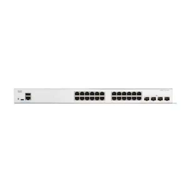
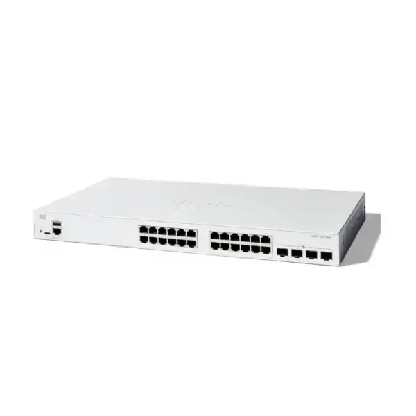
Cisco Catalyst C1300-24T-4X Network Switch
A high-performance 24-port Gigabit managed switch with four 10 Gigabit SFP+ uplinks, hardware stacking, Layer 3 routing, advanced access security, quiet fanless operation, and the capacity needed for modern UAE branch, office, campus-edge, retail, education, hospitality, and distributed enterprise networks.
This specific C1300-24T-4X SKU is non-PoE. It is intended for endpoints that do not require power from the Ethernet switch, or for environments where PoE is provided by another access layer.
95.23 Mpps forwarding rate
Fanless 1U rack-mount design
Direct answer: who should deploy the C1300-24T-4X?
The Cisco Catalyst C1300-24T-4X is best suited to organizations that need a compact but technically capable managed access switch with conventional 1 Gigabit copper connectivity at the edge and substantially faster 10 Gigabit optical uplinks toward a firewall, server switch, distribution layer, storage segment, or another wiring closet. It is particularly strong where 24 access ports are enough for the local device count but uplink congestion is a concern. Four independent SFP+ interfaces give network architects room for redundant uplinks, link aggregation, separate server or storage connections, or hardware stacking without forcing all east-west and north-south traffic through a single 1 Gigabit path.
For Dubai and wider UAE deployments, this model is relevant to professional offices, clinics, schools, shops, warehouses, serviced offices, branch locations, SMB data rooms, surveillance back-end networks where cameras are powered elsewhere, and distributed enterprise sites that need secure segmentation and manageable Layer 3 services. Buyers should choose a PoE-capable Catalyst 1300 variant instead when the switch must directly power Wi-Fi access points, IP phones, access-control readers, or IP cameras. That distinction is essential during sizing because the C1300-24T-4X provides data connectivity only on its 24 copper access ports.
Copper Gigabit Ethernet ports for desktops, servers, printers, appliances, firewalls, controllers, NVRs and other wired endpoints.
High-bandwidth fiber or supported direct-attach uplinks for aggregation, redundancy, stacking or high-speed server connectivity.
Wire-speed, nonblocking switching capacity sized for simultaneous traffic across the Gigabit access and 10 Gigabit uplink interfaces.
Published forwarding performance using 64-byte packets, supporting high packet-rate business traffic without relying on oversubscribed switching fabric.
A 444.3 × 240 × 43.94 mm chassis with no system fan, suitable for quiet offices and compact communications rooms.
This T-model does not provide endpoint power. Select a C1300 P/FP model if powered phones, cameras or wireless access points are required.
Hardware architecture and port-map engineering
The value of the C1300-24T-4X starts with a practical port map: twenty-four 10/100/1000BASE-T access interfaces sit alongside four dedicated 10 Gigabit SFP+ ports. Unlike a basic 24-port switch whose uplinks are also limited to 1 Gigabit, the four 10G interfaces create a much healthier oversubscription ratio for traffic leaving the access layer. A fully populated switch can theoretically receive 24 Gbps of unidirectional access traffic from attached devices. A single 10G uplink already provides ten times the bandwidth of a traditional 1G uplink, while multiple uplinks can be distributed across separate logical roles or combined where the topology and upstream device support link aggregation.
Cisco publishes the C1300-24T-4X with 128 Gbps switching capacity and 95.23 million packets per second of forwarding performance. Those numbers are more useful than an unverified marketing reference to a named ASIC. Cisco does not publish a specific switching-ASIC part number for this model in the current product data sheet, so a technically responsible design should focus on the documented behavior: wire-speed nonblocking forwarding, hardware-based switching and routing functions, 1.5 MB packet buffer for this SKU, a 16,000-address MAC table for the Catalyst 1300 Gigabit Ethernet class, and jumbo-frame support up to 9,000 bytes. These are the properties that materially affect application behavior and sizing.
The four SFP+ ports can be treated as a design resource rather than merely as uplinks. In a small server room, one pair may connect redundantly to a firewall or core while another pair connects to a virtualization host or NAS. In a multi-floor office, they can be used for fiber uplinks to upstream distribution equipment and for stack interconnects. In a branch, separate 10G paths can keep storage replication, user access and security inspection traffic from competing unnecessarily. The exact allocation depends on redundancy goals, available fiber, chosen optics, expected utilization and whether hardware stacking is required.
Performance sizing: interpreting 128 Gbps and 95.23 Mpps
A switching-capacity number is only valuable when it is translated into traffic engineering. The C1300-24T-4X combines twenty-four 1G copper ports and four 10G SFP+ interfaces. If every physical interface is counted in both transmit and receive directions, the aggregate theoretical bandwidth corresponds to the published 128 Gbps fabric figure. That is why Cisco can classify the platform as wire-speed and nonblocking: the switching fabric is dimensioned to avoid an artificial internal bottleneck when ports are active at line rate. Real deployments rarely sustain maximum bidirectional load on every port, but the fabric margin matters during microbursts, backups, large file transfers and periods when many endpoints become active simultaneously.
The 95.23 Mpps forwarding figure is based on minimum-size 64-byte packets, which stress packet-processing rate far more severely than large frames. Small-packet workloads appear in DNS, voice signaling, security events, monitoring, transactional applications and many control-plane-adjacent flows. A switch that can sustain high packet rates without collapsing latency is therefore more useful than one evaluated only by large-file throughput. At the same time, application design should not assume the switch will compensate for an undersized WAN, firewall, server NIC or storage target. End-to-end performance is limited by the slowest component along the path.
For a 24-user office with ordinary SaaS, collaboration and printing, a single 10G uplink can provide significant headroom. For a design with local virtualization, CAD files, media assets, large backups or multiple network segments routing through an upstream firewall, using two or more 10G paths may be sensible. Link aggregation can provide combined capacity and resiliency, but individual flows are normally hashed to a member link rather than split packet-by-packet. Consequently, a two-link 20G logical aggregate does not automatically make one single TCP flow run at 20 Gbps; it creates more aggregate bandwidth for multiple concurrent flows and adds link resilience.
The published 1.5 MB packet buffer should also be understood correctly. Buffering is not a substitute for capacity planning. Buffers absorb short bursts when ingress momentarily exceeds egress, but sustained oversubscription still results in queue growth, latency and eventually drops. The strongest deployments use 10G uplinks to reduce persistent congestion, define QoS for latency-sensitive classes and monitor interface counters so that design changes are based on evidence rather than assumptions.
10 Gigabit SFP+ uplinks: where the model earns its place
Four 10G SFP+ ports are the defining reason to choose the C1300-24T-4X over lower-tier 24-port access switches with only Gigabit uplinks. They can connect the access layer to a faster core or firewall, terminate fiber between floors, provide dedicated high-speed paths to servers or storage, or form stack links between compatible Catalyst 1300 family members. The physical medium should be selected from Cisco-supported transceiver and cabling options appropriate to distance, fiber type and equipment on the far end.
Within one communications room, supported direct-attach copper may be attractive for short rack-to-rack or device-to-device links because it can reduce optical component count. Across floors or buildings, multimode or single-mode fiber is typically more appropriate. The optical budget, connector type, patch-panel path, fiber grade and transceiver compatibility should all be confirmed before procurement. Buyers should avoid treating all SFP+ modules as interchangeable simply because the cages have the same shape. Support status, speed coding, wavelength and distance must match the physical plant and the peer interface.
Redundant uplink architecture is especially important in UAE business environments where a small branch may depend on cloud applications, hosted telephony, ERP access or centralized security. A single failed uplink can isolate an otherwise healthy switch. By using independent uplinks toward redundant upstream paths, or by designing a resilient stack and cross-stack link aggregation where supported, the local access layer can continue forwarding through surviving connectivity. The correct topology depends on whether the upstream pair operates as a logical system, supports multi-chassis link aggregation, or requires Spanning Tree to manage redundant Layer 2 paths.
For organizations reviewing broader network and infrastructure architecture, FourTeck’s UAE team can align the switch with firewall, routing, server and cabling requirements through FourTeck UAE. The goal should be to size the uplinks as part of the complete data path, not as an isolated specification line.
Layer 2 segmentation, VLAN design and loop prevention
The Catalyst C1300 software feature set allows the switch to serve as far more than an unmanaged Ethernet fan-out. Cisco documents support for port-based and IEEE 802.1Q tagged VLANs, MAC-based VLANs, protocol-based VLANs, IP-subnet-based VLANs, a dedicated management VLAN, guest and unauthenticated VLAN behavior, private VLAN constructs, dynamic VLAN assignment through RADIUS with 802.1X authentication, voice VLAN functions and additional service-provider-style mechanisms such as VLAN translation and Q-in-Q. The platform supports a large VLAN namespace, giving designers enough logical separation for typical SMB and branch requirements without collapsing unrelated device classes into one broadcast domain.
A well-designed UAE office might separate corporate users, finance systems, guest access, building management, printers, servers, CCTV back-end equipment, voice infrastructure and switch management. Segmentation does not automatically create security; inter-VLAN traffic still needs routing policy and, where appropriate, firewall inspection. But VLAN boundaries create the structure required to apply those controls. They also reduce broadcast scope and make troubleshooting more deterministic because devices can be grouped by function rather than by whichever physical port was available during installation.
Loop prevention is handled through standards-based Spanning Tree options. Cisco documents classic 802.1D STP, Rapid Spanning Tree under 802.1w, Multiple Spanning Tree under 802.1s, and Cisco-compatible per-VLAN variants including PVST+ and Rapid PVST+. BPDU Guard, Root Guard and loopback protection add operational safeguards at the edge. These features matter because accidental loops created by a patch cable, unmanaged switch or miswired endpoint can generate broadcast storms severe enough to disrupt an entire Layer 2 domain. Edge ports should therefore be classified and protected deliberately rather than left with a one-size-fits-all configuration.
Link Aggregation Control Protocol under IEEE 802.3ad is supported, with Cisco documenting up to eight aggregation groups and up to eight active ports per group, subject to platform configuration rules. Aggregation is useful both for increasing total bandwidth across parallel links and for retaining connectivity when one physical member fails. Designers should keep the logical topology simple: uplinks, LAGs, VLAN trunks and Spanning Tree roles must be documented so that the network behaves predictably during a failure rather than only during normal operation.
Layer 3 routing for branch and access networks
The C1300-24T-4X supports Layer 3 functionality, allowing IP routing to be performed on the switch rather than forcing every inter-VLAN packet to traverse an external router. Cisco’s Catalyst 1300 feature set includes wire-speed IPv4 routing, IPv6 routing, Layer 3 interfaces on physical ports, link aggregates, VLAN interfaces and loopback interfaces, Classless Inter-Domain Routing, RIP version 2, policy-based routing, DHCP server capability, DHCP relay and UDP relay. These features allow the platform to act as a practical distribution or advanced access switch in smaller networks.
Static routing is often the most appropriate choice for a compact branch. For example, user, server and printer VLANs can terminate on switch virtual interfaces, with a default route pointing toward the perimeter firewall. That arrangement keeps routine east-west traffic local while directing internet, WAN or protected-zone traffic to the security appliance. Policy-based routing can be used when selected flows must be steered toward a different next hop based on source or destination policy. Dynamic routing should only be introduced when the topology benefits from it and the operations team has the skills to troubleshoot convergence and route selection.
A crucial product-family distinction is that Cisco lists OSPFv2 and OSPFv3 for Catalyst 1300X SKUs, not for the standard C1300 family. Therefore, a buyer who specifically requires OSPF should not assume that the C1300-24T-4X provides the same routing feature depth as a C1300X. For this model, RIP v2, static routes and policy-based routing cover many branch scenarios, but advanced routing requirements should be validated before purchase. This kind of feature boundary matters more than raw port count when the switch is expected to participate actively in a routed campus design.
Layer 3 on the switch also changes the security model. When two VLANs route locally, traffic between them does not automatically pass through an external firewall. Access control lists, source validation and segmentation policy must therefore be designed intentionally. In higher-security environments, organizations may prefer to route sensitive VLANs through a next-generation firewall even if the switch can route them locally. FourTeck can coordinate switch and security architecture through the specialist team at Firewall Dubai so that performance and inspection requirements are balanced correctly.
Hardware stacking, resiliency and operational scale
Cisco supports hardware stacking on the C1300-24T-4X as part of the compatible Catalyst 1300 family. Up to eight supported switches can participate in a stack, with Cisco describing up to 400 ports managed as a single system and hardware failover for stack control. The stack can operate with active and standby control, automatic numbering, hot-swap behavior for members, ring or chain arrangements, and flexible use of high-speed 10 Gigabit interfaces for interconnects. These capabilities are important for organizations that expect a 24-port deployment to grow into multiple access switches over time.
A true hardware stack differs from simply placing several independently managed switches next to each other. The stack is intended to behave as one logical entity across control and data planes, reducing the number of separate devices administrators must configure. Cisco also supports link aggregation across multiple stack members, which is valuable for resilient uplinks or servers with dual network paths. If one member experiences a hardware issue, connectivity through surviving members and links can remain available depending on how endpoints and uplinks are physically distributed.
Stack planning should happen before optics are ordered because the same high-speed interface resources may be needed for stack interconnects and upstream connectivity. Designers should decide the desired number of members, ring versus chain resilience, physical rack position, inter-switch link type, required uplink bandwidth and spare-port strategy. A ring provides a more resilient interconnect path than a simple chain because traffic can potentially reach the control path in either direction if one stack link fails. The exact operational outcome still depends on the failure scenario and configuration.
Compatibility must also be respected. Cisco separates Catalyst 1300 stacking into families, and product IDs from the same family can be stacked together while cross-family stacking is not supported. A C1300-24T-4X should therefore be planned with compatible C1300 family-one models rather than assuming arbitrary mixing with 10G access SKUs or C1300X units. This is particularly relevant in phased projects where procurement happens across multiple quarters.
Operationally, stacking reduces configuration drift, makes port expansion simpler and can improve high availability. It should not be confused with disaster recovery, however. A stack in one rack shares environmental risks such as power, cooling, cabling accidents and room access. Critical sites may require redundant UPS feeds, diverse uplink paths, separate physical locations or a two-tier architecture in addition to stack-level resiliency.
Security controls for authenticated and segmented access
A business access switch is part of the security boundary because it determines which devices can enter the network and what traffic they can originate. Cisco equips the Catalyst 1300 family with IEEE 802.1X authentication, RADIUS integration, MAC authentication options, dynamic VLAN assignment, port security, web-based authentication, DHCP snooping, IP Source Guard, dynamic ARP inspection, Spanning Tree safeguards and IPv6 first-hop protections. These functions are useful against common local-network risks such as rogue DHCP servers, address spoofing, unauthorized endpoints and accidental or malicious Layer 2 topology changes.
802.1X allows the switch to act as an authenticator, requiring a user or endpoint to prove identity through a RADIUS-backed access-control workflow before normal network service is granted. Dynamic VLAN assignment can then place the endpoint into the correct segment based on policy rather than fixed patch-panel position. For devices that cannot run a standard 802.1X supplicant, MAC-based methods or controlled fallback policies may be used, but these should be treated as lower-assurance mechanisms. The operational objective is to prevent every wall jack from automatically becoming trusted corporate access.
DHCP snooping builds trust boundaries around legitimate DHCP server paths. IP Source Guard can then reject packets whose source addressing does not match trusted bindings, reducing IP spoofing risk. Dynamic ARP inspection uses related binding information to detect invalid ARP behavior that could otherwise support man-in-the-middle attacks. For IPv6, RA Guard, Neighbor Discovery inspection, DHCPv6 Guard and neighbor-binding integrity controls provide analogous first-hop protection. These features become increasingly important as networks move toward dual-stack operation rather than assuming IPv6 traffic is harmless or absent.
Management access should be secured independently from user traffic. The platform supports SSH and HTTPS for encrypted administration as well as SNMPv3 for authenticated and encrypted monitoring. Best practice is to place management interfaces in a dedicated VLAN, restrict source addresses using ACLs, use strong unique credentials or centralized AAA where appropriate, disable unused services, prefer modern cryptographic modes, maintain configuration backups and keep firmware at a validated supported release. Merely having security features available does not provide protection until they are configured and monitored.
For UAE organizations subject to internal audit, customer security requirements or cyber-insurance controls, these switch-level features can support a broader zero-trust or least-privilege approach. They should be integrated with firewall policy, endpoint security, logging and identity systems rather than deployed in isolation.
Important: this is a non-PoE switch
The “T” in C1300-24T-4X identifies a data-only copper access configuration. The 24 RJ45 ports do not supply IEEE 802.3af or 802.3at power to attached devices. That makes the model efficient for conventional desktops, servers, network appliances, printers, industrial controllers with independent power, storage systems and uplink duties, but it means an IP phone, wireless access point or powered security camera cannot be energized directly from the switch.
If a project mixes powered and non-powered endpoints, there are several design choices. A separate PoE access switch can serve phones, cameras and APs while the C1300-24T-4X carries non-PoE data devices and 10G uplinks. Individual power injectors may be suitable for a very small number of powered endpoints, though they add cabling and support complexity. The cleaner option for a heavily PoE-dependent access layer is normally a C1300-24P-4X or C1300-24FP-4X class model, selected according to the required PoE budget.
This distinction should be settled before quotation because changing from non-PoE to PoE affects switch model, power consumption, UPS sizing, rack thermals and sometimes depth. A correct Bill of Materials considers endpoint power draw, port count, future growth, redundancy and uplink needs together rather than selecting a switch only by its number of Ethernet ports.
Quality of Service for voice, video and business-critical applications
The Catalyst 1300 family provides eight hardware queues and supports strict-priority and weighted round-robin scheduling. Classification can use port, 802.1p Class of Service, IPv4 or IPv6 precedence, DSCP markings, DiffServ behavior and ACL-based classification. Ingress policing, egress shaping and rate controls can be applied to manage how traffic enters and leaves the switch. These capabilities are valuable whenever latency-sensitive flows share the same physical infrastructure with backups, software distribution, large file transfers or guest traffic.
QoS should begin with a traffic model. Real-time voice usually needs low delay, low jitter and controlled packet loss, but it consumes relatively little bandwidth. Video conferencing consumes more bandwidth and can be bursty. ERP, databases and interactive SaaS may be sensitive to delay but should not automatically receive strict priority. Backup and synchronization traffic can usually tolerate more delay but may fill links if unrestricted. A practical policy identifies trusted traffic sources, preserves or rewrites markings at appropriate boundaries and reserves strict priority for a limited class so that other applications cannot be starved.
Voice VLAN functionality can automatically place compatible voice endpoints into a dedicated VLAN and apply appropriate QoS treatment. Even on this non-PoE model, voice traffic can still be switched if phones are independently powered or connected through another powered access layer. The switch also supports LLDP and LLDP-MED style device discovery capabilities that can simplify endpoint identification and policy application. Auto Smartports can apply predefined behavior based on detected device roles, helping reduce repetitive configuration in standardized branches.
QoS does not create bandwidth. If a 10G uplink is consistently saturated, policy can determine which traffic gets served first, but capacity expansion remains the proper remedy for chronic congestion. Administrators should combine queue counters, interface utilization, drop statistics and application observations to decide whether a problem is caused by bandwidth, packet loss, server latency, WAN limitations or incorrect classification.
Management, monitoring and deployment automation
Cisco provides multiple administration methods for the Catalyst 1300 platform. The embedded web user interface supports browser-based configuration over HTTP or HTTPS, with simple and advanced modes, wizards, dashboards, monitoring, system maintenance and search. For network engineers, command-line administration supports more deterministic configuration and easier reuse of templates. SNMP versions 1, 2c and 3 are supported for monitoring, with SNMPv3 preferred where authentication and privacy are required. Syslog, RMON, port mirroring and standard management information bases help integrate the switch into broader operational tooling.
Cisco Network Plug and Play support is relevant for organizations rolling out standardized branches. Rather than having an engineer manually build every switch from an empty configuration, a provisioning workflow can associate a device with its intended configuration and reduce on-site effort. Text-editable configuration files can also be prepared centrally and transferred to devices, while Smartports and Auto Smartports simplify common interface roles. These methods are especially useful in multi-site UAE deployments where the cost of repeated travel can exceed the cost of the networking hardware itself.
Good operations depend on observability. Interface utilization and error counters reveal duplex problems, bad cabling, congestion and failing optics. MAC-address tables help confirm where endpoints are learned. Spanning Tree state shows active and blocked topology paths. LACP status confirms which member links are forwarding. DHCP snooping and security logs provide evidence when a device is rejected. Environmental and uptime data help distinguish power events from network faults. SNMP polling and syslog forwarding should be configured before an incident, not after the first outage.
Firmware lifecycle management should include a pre-upgrade backup, release-note review, compatibility check and rollback plan. Cisco supports dual images on the Catalyst 1300 family, which can reduce operational risk during software maintenance. Organizations should nevertheless schedule changes, validate saved configuration, document the current firmware and confirm management access out of band or through a resilient path when practical.
Customers who want assistance with switch installation, VLAN migration, rack work, structured cabling coordination, firmware standardization, network monitoring and ongoing support can use FourTeck’s IT Services UAE resources as part of the deployment plan.
Physical design, power, thermals and rack planning
The C1300-24T-4X uses a 1U rack-mountable chassis measuring approximately 444.3 mm wide, 240 mm deep and 43.94 mm high, with a published weight of about 3.14 kg. Its shallow depth is useful in compact wall-mounted or floor-standing communications cabinets where deeper enterprise switches may be awkward. The 24-port and 48-port models include 19-inch rack-mount brackets, making the unit straightforward to integrate into standard structured-cabling racks.
A major operational advantage of this SKU is fanless cooling. Cisco publishes the C1300-24T-4X as a fanless model, which reduces acoustic noise and removes a common moving component from the chassis. That makes it appropriate for open offices, retail back rooms, classrooms, clinics and small network cupboards located close to occupied spaces. Fanless does not mean ventilation is irrelevant. The cabinet still needs clear airflow around equipment, and ambient temperature must stay within the supported range.
Cisco specifies an operating temperature range from -5°C to 50°C, with a minimum cold-start ambient of 0°C, and relative operating humidity of 10% to 90% noncondensing. UAE deployments should pay particular attention to cabinet temperature because room heat, direct sunlight, failed air conditioning and dust buildup can raise equipment temperature well above the building’s nominal thermostat setting. A network cupboard near a warehouse ceiling or exterior wall may experience very different conditions from an air-conditioned office.
The switch uses a universal 100–240V AC, 50–60 Hz internal power supply. Cisco publishes worst-case system power consumption around 22.3W at 110V and 22.4W at 220V, with idle values around 4.9W and 5.2W respectively. Because this is a non-PoE model, there is no large endpoint-power budget to add to UPS sizing. Even so, the UPS should account for the switch, firewall, ISP equipment, optical converters if any, management appliances and expected runtime. Surge protection and clean grounding should follow local electrical practices and rack standards.
Cisco also supports IEEE 802.3az Energy Efficient Ethernet on Gigabit copper ports, cable-length-aware signal adjustment, link-down power reduction and related efficiency features. These mechanisms reduce unnecessary consumption during low utilization without changing the need for proper capacity. The published MTBF at 25°C for this model is 646,083 hours, a statistical reliability metric useful for comparison but not a guarantee that any individual unit will operate for a specific number of years.
In physical planning, allow room for patch-cord bend radius, fiber management, SFP+ removal, power-cable access and labeling. A switch that technically fits a cabinet can still be difficult to service if patch panels, PDUs or door clearance obstruct the front and rear. Serviceability should be considered before final rack elevation is approved.
Optics, fiber and copper cabling strategy
The 24 copper access ports use standard Gigabit Ethernet over twisted-pair cabling. For new installations, structured cabling should be tested and labeled end to end rather than judged only by whether a link light appears. Cat5e can support 1 Gigabit Ethernet within standards-defined distance, while Cat6 or better may be chosen for new builds to provide additional headroom and future flexibility. Patch cords, keystone modules, patch panels and permanent links must all be part of the same quality chain; one poor termination can create CRC errors or intermittent negotiation problems that resemble switch faults.
The SFP+ uplinks require a media decision. Multimode fiber is often economical for short in-building links and data-room interconnects, while single-mode fiber is preferred for longer distances and gives greater future flexibility. The correct transceiver depends on wavelength, fiber type, connectorization and maximum engineered distance. Both ends of the link must use compatible optics and must agree on the Ethernet speed. The fact that an optic physically inserts into an SFP+ cage does not prove interoperability.
When reusing existing fiber in a Dubai building, verify strand count, fiber grade, connector type, patch-panel path and measured optical loss. Older multimode plant may have limitations at 10 Gigabit distances that were never relevant when the link operated at 1 Gigabit. For cross-building connections, consider grounding isolation, diverse routes, outdoor-rated fiber where appropriate and the possibility of carrier handoff equipment. Fiber generally avoids electrical potential differences that can affect copper between buildings.
For short same-rack or adjacent-rack connections, supported SFP+ direct-attach cabling can reduce power, cost and optical complexity. However, cable length and bend radius are fixed constraints, and compatibility with the peer device must be confirmed. A firewall from another vendor, for example, may have its own supported DAC or transceiver list. A procurement team should therefore quote optics only after the device pair and physical distance are known.
Spare optics are often worth including for critical sites because a failed transceiver can take down an otherwise healthy uplink. Label the installed optic type, wavelength and destination on the rack documentation so support engineers can replace like for like without guessing during an outage.
Sizing methodology for a 24-port access layer
Port count should be sized from actual endpoint inventory plus growth, not from the number of desks alone. A 20-person branch may need more than 24 ports once printers, conference-room systems, access-control panels, servers, firewalls, NAS devices, building systems, management interfaces and spare ports are counted. Conversely, a 40-person hybrid office may fit within 24 active switch ports if most users rely on wireless and only shared infrastructure is wired. The correct count comes from a room-by-room endpoint schedule.
Reserve capacity has operational value. Keeping several access ports free makes moves, additions and emergency replacements easier and reduces the temptation to add unmanaged desktop switches. For a new site, a practical target is often to avoid day-one port utilization close to 100%. If the forecast shows rapid expansion beyond 24 ports, a 48-port model or a planned two-member stack may be more economical than replacing the first switch shortly after installation.
Bandwidth sizing should separate edge speed from uplink demand. Most desktops do not continuously transmit at 1 Gbps, but aggregated backups, local file access, virtualization and surveillance recording can create large bursts. If the site is primarily SaaS-based with a 500 Mbps internet circuit, the 10G uplinks may appear excessive until redundancy, local servers and future WAN upgrades are considered. If the site contains 10G-capable storage or hosts, the SFP+ ports can be used directly for selected high-bandwidth links while the 1G ports serve ordinary endpoints.
Traffic direction matters. North-south traffic goes toward WAN, internet or centralized services; east-west traffic remains within the branch between users, servers, storage and local applications. A site with heavy east-west traffic benefits more directly from local switching and 10G aggregation than one where nearly every packet exits through a slow WAN. VLAN routing placement also changes traffic flow: local Layer 3 switching can prevent unnecessary firewall hairpinning, while security policy may intentionally require selected traffic to traverse the firewall.
Finally, count high-speed ports as carefully as access ports. If two SFP+ interfaces are needed for a resilient stack ring and two more for redundant upstream connections, all four may be allocated immediately. Future high-speed server connectivity would then require another design. A Bill of Materials should therefore include not only switch quantity but also uplink role, stacking role, transceiver quantity, fiber pairs and spare strategy.
Deployment topology 1: secure UAE branch office
In a typical Dubai branch, the C1300-24T-4X can sit behind a next-generation firewall. Corporate laptops, desktops, printers and local appliances connect to Gigabit access ports. Separate VLANs are created for users, finance, printers, building systems and management. One or two 10G SFP+ uplinks connect to the firewall or an upstream distribution device, depending on the firewall’s interface capability. If the firewall cannot accept 10G, the SFP+ resource can still be used for servers or a future core while a Gigabit path carries WAN-bound traffic.
The switch can perform local routing for lower-risk internal VLANs, with a default route toward the firewall, or the firewall can terminate the VLANs where inspection between segments is required. DHCP can be centralized elsewhere and reached through DHCP relay, or the switch can provide DHCP service in a compact standalone design. 802.1X can authenticate managed users, while guest or unauthenticated VLAN behavior can isolate devices that do not meet access policy.
A branch with a second C1300 can use hardware stacking to simplify management and provide more ports. Uplinks can be distributed across stack members so the failure of one unit does not remove every upstream path. The exact topology should be lab-tested for failover behavior, especially if the upstream firewall pair uses active/passive high availability or a vendor-specific multi-chassis link design.
This topology is attractive because it provides enterprise-style segmentation, authentication and redundancy without requiring a large chassis switch. It also preserves a path to growth: more stack members can be added within compatibility rules, while 10G connectivity provides headroom for faster security appliances and server infrastructure.
Deployment topology 2: office, school or clinic with separate PoE access
Many real sites contain a mixture of powered and non-powered endpoints. In that case, the C1300-24T-4X can be paired with a PoE access switch. The non-PoE C1300 handles workstations, printers, servers, NVRs and infrastructure ports, while the PoE switch serves phones, cameras and Wi-Fi access points. Both switches connect over 10G to a common distribution layer or can be arranged within compatible stacking rules where the chosen models support the same family.
This separation can be beneficial when the PoE load is concentrated. Rather than paying for powered ports on every switch, the project places PoE capacity only where needed. It also simplifies UPS calculations because the endpoint-power draw is isolated to the powered switch. On the other hand, if almost every user port serves an IP phone with a PC daisy-chained behind it, a non-PoE access switch is usually the wrong primary choice.
Schools and clinics should pay attention to segmentation. Student, staff, administrative, guest, medical-device, CCTV and building-management networks may have very different security requirements. The Catalyst 1300 feature set supports the VLAN, 802.1X, ACL and first-hop security controls needed to create those boundaries. Policy should be driven by the organization’s risk model rather than by convenient port grouping.
Because the C1300-24T-4X is fanless, it also works well in occupied environments where an access switch may be installed in a nearby cabinet rather than a dedicated data room. Physical security remains important: a locked rack, controlled patching and documented ports protect against accidental changes and unauthorized connection.
Deployment topology 3: server, storage and aggregation edge
Although the access ports are 1 Gigabit, the four SFP+ interfaces make the C1300-24T-4X useful in compact server and storage environments where only a few systems need 10G. For example, two SFP+ ports can connect to a virtualization host or storage appliance while the remaining two connect upstream. The 24 Gigabit ports can serve management interfaces, backup appliances, hypervisor management networks, iDRAC/iLO-style service ports, printers or other infrastructure devices that do not require 10G.
iSCSI traffic optimization and QoS features can help prioritize storage traffic when it shares the switching fabric with ordinary data, but storage design still requires careful attention to latency, MTU consistency and redundancy. Jumbo frames up to 9,000 bytes are supported, yet every device along a jumbo-frame path must be configured compatibly. A mismatch can cause fragmentation, black holes or confusing application symptoms. The default MTU and any storage-specific MTU should therefore be documented and validated end to end.
A compact aggregation design should also consider failure domains. If both storage paths, server uplinks and upstream firewall paths terminate on one switch, that switch becomes a single point of failure even if individual links are redundant. A two-member stack or dual-switch architecture can distribute critical connections. Server NIC teaming or bonding modes must match the switch-side LAG design, especially where LACP is used.
This use case is most appropriate when the environment needs a modest number of 10G ports. If a rack contains many 10G servers, a Catalyst 1300 model with native 10G access interfaces or a higher-capacity data-center switching platform would be a better fit. The C1300-24T-4X is strongest when 1G remains the dominant edge speed and a small number of 10G links provide aggregation and acceleration.
How this model compares within the Catalyst 1300 family
The C1300-24T-4X sits in a useful middle position. Compared with the C1300-24T-4G, it keeps the same 24 Gigabit copper access ports but upgrades the uplink block from four 1G SFP interfaces to four 10G SFP+ interfaces. That change raises switching capacity significantly and is the main reason to select the 4X model for networks with faster firewalls, fiber backbones, servers or stack requirements.
Compared with the C1300-24P-4X or C1300-24FP-4X, the C1300-24T-4X removes PoE. Buyers who do not need powered endpoints benefit from lower power draw, lower thermal load and a fanless design without paying for a PoE power subsystem they will not use. Buyers who need to power phones, APs or cameras should choose the P or FP variant based on required PoE budget rather than trying to compensate with a large collection of external injectors.
Compared with the 48-port 4X models, the 24T-4X is better suited to smaller racks and sites with moderate port density. A 48-port switch may offer a lower cost per access port and more growth space, but it can be unnecessary if the branch will never approach that density. Conversely, deploying two 24-port switches purely to reach 48 ports may consume more rack units and uplink resources than a single 48-port model, though it can provide different resiliency options.
Catalyst 1300X models add a different feature tier, including higher routing scale on specified SKUs and OSPF support that Cisco lists for the 1300X family. Some 1300X models also use SFP28-capable interfaces with 25G available for stacking in defined cases. Customers requiring those capabilities should compare the product family rather than assuming that the C1300 and C1300X suffixes are interchangeable.
The decision should therefore start with four questions: how many copper endpoints are required, whether PoE is required, how many 10G or faster links are needed, and which Layer 3 protocols must be supported. Answering those questions usually narrows the correct Catalyst 1300 model quickly.
UAE procurement and lifecycle considerations
For network hardware procurement in the UAE, model accuracy matters because Catalyst product names can differ by only a few characters while representing meaningful differences in power, port speed and feature tier. The quotation should state C1300-24T-4X explicitly and list every accessory needed for deployment: power cord selection, SFP+ optics or DACs, fiber patch cords, rack hardware, console or management requirements, spare transceivers, UPS capacity and any installation services. A buyer should not assume optics are included simply because the switch has SFP+ cages.
Cisco lists a limited lifetime warranty with return-to-factory replacement for the Catalyst 1300 family, together with complimentary access to the Small Business Support Center for the first year under the published program terms. Organizations with stricter replacement-time objectives should confirm available support options, local stock strategy and internal sparing requirements. A branch that cannot tolerate an extended outage may justify keeping a compatible spare switch on site even when vendor warranty is active.
Firmware support and configuration standardization should be part of procurement, especially when several switches are purchased over time. Newer stock may arrive with different firmware than existing units. Before stacking or deploying standardized templates, engineers should confirm software compatibility, back up running configurations and use a controlled upgrade path. Asset records should capture serial number, exact PID, firmware version, rack position, uplink destination, management address and warranty information.
Regional environmental conditions also affect lifecycle. Dust, high ambient temperature, inadequate cabinet airflow and unstable utility power can shorten equipment life even when the switch itself is fanless and efficient. Network rooms should be treated as infrastructure spaces, with clean power, controlled access, adequate cooling and periodic inspection. Patch-cord strain, blocked ventilation and overloaded low-cost power strips are common operational risks that are avoidable with good rack discipline.
FourTeck can also support organizations operating across multiple regions through its broader global technology platform, helping standardize product selection and deployment approaches where UAE branches are part of a larger international network.
Operational best practices after installation
A well-specified switch can still become difficult to operate if documentation and configuration hygiene are ignored. Start by assigning a descriptive hostname, management IP, location and contact information. Place management access in a dedicated VLAN, restrict it to trusted administrator subnets and use HTTPS, SSHv2 and SNMPv3 where appropriate. Disable unused switch ports or place them into an isolated parking VLAN, and document any exceptions. Avoid leaving default credentials or broad management exposure in place after commissioning.
Name interfaces by destination. Labels such as “FINANCE-PRINTER-03” or “UPLINK-FW-A” shorten troubleshooting time compared with anonymous port numbers. Maintain a matching rack diagram and patch-panel schedule. When a cable is moved, update both physical and logical documentation. A technically advanced switch does not eliminate the need for physical-layer discipline.
Build VLANs and trunks deliberately. Limit trunk allowed-VLAN lists where practical rather than carrying every VLAN everywhere. Define native VLAN behavior consistently. Enable edge-port protections such as BPDU Guard on ports that should never receive bridge protocol traffic. Use storm control and loop protection according to the network standard. For LACP uplinks, confirm both the logical aggregate state and individual member health.
Centralize logging and time synchronization. Accurate timestamps are critical when correlating a switch event with firewall logs, authentication failures or server incidents. Monitor temperature, uptime, link flaps, CRC errors, discarded packets, CPU or memory alerts where exposed, stack state and authentication failures. Set thresholds based on normal behavior so alerts identify meaningful deviation rather than generating noise.
Back up configuration after every approved change and retain a known-good version off the device. Test restore procedures before an emergency. Maintain a firmware policy that balances security fixes, feature requirements and stability. Review Cisco release notes before upgrades, especially in stacked environments or where transceiver interoperability is critical.
Finally, revisit capacity at least annually or after major application changes. Growth in cloud use, surveillance retention, local backups, Wi-Fi density or server virtualization can change traffic patterns even when the number of copper endpoints stays constant. The four 10G uplinks provide useful headroom, but monitoring should determine when that headroom is being consumed.
Frequently asked technical questions
Does the C1300-24T-4X provide PoE?
No. It is a 24-port non-PoE data switch. Use a C1300 P or FP model when Ethernet-powered endpoints are required.
Are the four uplinks really 10 Gigabit?
Yes. Cisco specifies four 10 Gigabit SFP+ interfaces on the C1300-24T-4X, in addition to the 24 Gigabit copper access ports.
Can this switch be stacked?
Yes. The model supports hardware stacking with compatible Catalyst 1300 family members, with up to eight switches in a supported stack design.
Does it support Layer 3 routing?
Yes. The Catalyst 1300 platform supports wire-speed IPv4 and IPv6 routing plus static routing, RIP v2, policy-based routing, DHCP server and relay functions. OSPF is listed for C1300X models rather than this standard C1300 SKU.
Is it suitable for quiet offices?
Yes. Cisco lists the C1300-24T-4X as fanless, so it avoids normal fan noise while still requiring appropriate cabinet ventilation and temperature control.
Can it secure user access?
Yes. Supported controls include 802.1X, RADIUS integration, port security, DHCP snooping, IP Source Guard, dynamic ARP inspection and IPv6 first-hop security features.
Detailed specification reference for C1300-24T-4X
| Product ID | C1300-24T-4X |
| Copper access ports | 24 × 10/100/1000 Gigabit Ethernet RJ45 |
| High-speed uplinks | 4 × 10 Gigabit SFP+ |
| PoE | Not supported on this T-model |
| Switching capacity | 128 Gbps |
| Forwarding rate | 95.23 Mpps at 64-byte packets |
| Packet buffer | 1.5 MB |
| MAC address table | 16,000 addresses for Catalyst 1300 Gigabit Ethernet SKUs |
| Jumbo frames | Up to 9,000 bytes |
| Stacking | Hardware stacking with compatible family; up to 8 switches in supported stack |
| VLANs | 802.1Q and advanced VLAN features; up to 4094 VLAN IDs with reserved internal range |
| QoS queues | 8 hardware queues |
| Layer 3 | IPv4/IPv6 routing, RIP v2, PBR, CIDR, DHCP server/relay and routed interfaces |
| Security | 802.1X, port security, DHCP snooping, IP Source Guard, dynamic ARP inspection, IPv6 first-hop security, HTTPS, SSH |
| Management | Web GUI, CLI, SNMP, Cisco Network Plug and Play, text configuration, Smartports |
| Dimensions | 444.3 × 240 × 43.94 mm |
| Weight | Approximately 3.14 kg |
| Cooling | Fanless |
| Power input | 100–240V AC, 50–60 Hz, internal universal supply |
| Worst-case system power | Approximately 22.3W at 110V / 22.4W at 220V |
| Operating temperature | -5°C to 50°C; minimum cold start 0°C |
| Operating humidity | 10% to 90% relative, noncondensing |
| Published MTBF at 25°C | 646,083 hours |
| Warranty | Limited lifetime with return-to-factory replacement under Cisco terms |
Why the C1300-24T-4X is relevant for Dubai business networks
Dubai organizations often operate in compact offices with a mix of cloud applications, centralized firewalls, local file services, managed Wi-Fi and increasing east-west traffic. A switch that provides only Gigabit uplinks can become the hidden bottleneck as endpoints, backups and internet speeds grow. The C1300-24T-4X retains cost-effective Gigabit access for ordinary devices while giving the network four 10G lanes for aggregation and resilience. This architecture aligns well with sites where user ports do not individually require multigigabit speed but the combined traffic from many users must move quickly toward shared services.
Its fanless form factor is also practical in offices where the network rack is located close to staff. Lower system power and no PoE subsystem reduce heat compared with powered access models, which can simplify small-cabinet design. At the same time, the switch delivers the managed features needed for secure business operation: authentication, VLAN segmentation, ACLs, routing, QoS, LAGs, stack resilience and encrypted management.
The product is not intended to replace every class of enterprise switch. Large campus cores, high-density multigigabit wireless access, environments requiring many 10G server ports, and networks that require advanced dynamic routing may need different platforms. Its strength is precisely defined: a robust 24-port Gigabit access layer with four 10G SFP+ interfaces and advanced SMB/branch management features.
For regional projects, FourTeck can align product selection with broader cabling, security, server and network requirements rather than treating the switch as a standalone line item. That reduces model mismatch and produces a Bill of Materials that accounts for optics, power, topology and implementation services from the start.
Decision recap: choose this model when the design matches
Strong fit
Choose the C1300-24T-4X when you need around 24 wired Gigabit endpoints, four 10G SFP+ interfaces, Layer 2 segmentation, practical Layer 3 routing, stacking, fanless operation, and no requirement to power endpoints from the switch.
Reconsider the model
Select a different variant if you need PoE, more than 24 access ports, many native multigigabit or 10G access interfaces, 25G requirements, or routing protocols such as OSPF that Cisco assigns to the C1300X feature tier.
Plan the accessories
Treat SFP+ optics, fiber or DACs, UPS capacity, patch panels, rack space, uplink topology, spare transceivers and implementation labor as part of the switch design. The base switch alone is not a complete connectivity solution.
Plan growth
Leave access-port and uplink headroom. If the site is likely to exceed 24 copper ports quickly, compare a 48-port model or a planned stack so the first purchase supports the expected lifecycle rather than only today’s occupancy.
Quotation input checklist for a correct UAE Bill of Materials
Before requesting a final quotation for the Cisco Catalyst C1300-24T-4X, provide the information below. A complete input set allows the switch, optics, rack accessories and services to be sized correctly and reduces change orders during installation.
Consult FourTeck for Cisco Catalyst C1300-24T-4X in Dubai, UAE
A correct switch purchase includes model selection, uplink media, VLAN and routing architecture, security controls, rack and UPS planning, migration method, firmware baseline and post-installation support. FourTeck can help translate the C1300-24T-4X specification into a deployment-ready Bill of Materials for your site.
For broader enterprise networking, infrastructure and regional technology requirements, explore FourTeck UAE and coordinate implementation requirements before equipment is ordered.

Reviews
There are no reviews yet.