
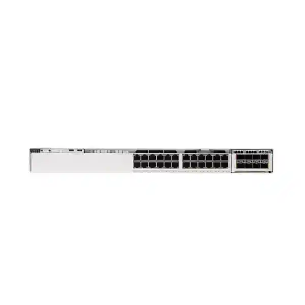
Cisco C9350-24T Smart Switch
A 24-port 1 Gigabit Ethernet, data-only access switch designed for modern campus and branch networks that need Cisco Silicon One forwarding, StackWise-1.6T resiliency, modular high-speed uplinks, programmable operations and enterprise-class Cisco IOS XE capabilities.
Choose the C9350-24T when you need 24 standard 1G copper access ports and do not need PoE on those ports. It is positioned for wired endpoints, servers, appliances, workstations, printers, security devices and other independently powered equipment, with modular uplink capacity and stacking for resilient enterprise designs.
Cisco C9350-24T overview for UAE networks
The Cisco C9350-24T Smart Switch is part of the C9350 Series, Cisco’s newer generation of enterprise access switching platforms built around Cisco Silicon One technology. The C9350-24T specifically provides 24 copper downlink ports supporting 10 Mbps, 100 Mbps and 1 Gbps Ethernet. It is a data-only model, meaning the access ports are intended to carry network traffic but do not provide Power over Ethernet to connected endpoints. That distinction matters when a network bill of materials is being prepared: organizations that need to power IP phones, wireless access points, cameras or other powered devices directly from the access switch should evaluate PoE-capable C9350 variants, while the C9350-24T is an efficient fit for independently powered devices and data-centric access closets.
For an enterprise architect, the value of the C9350-24T is not simply the number of RJ-45 ports. The platform is designed to combine predictable wired access, high-capacity stacking, optional modular uplinks, modern telemetry, programmable operations and enterprise routing and security functions in a single access-layer chassis. Cisco documents StackWise-1.6T support for the model, providing an architectural path to operate compatible switches as a resilient logical system with very high stack bandwidth. The switch also uses a Cisco Silicon One A100-family ASIC for hardware forwarding, aligning the access layer with Cisco’s broader silicon strategy and giving organizations a modern foundation for policy, visibility and lifecycle development.
In Dubai, Abu Dhabi, Sharjah and other UAE locations, the C9350-24T can be used in headquarters floors, branch offices, education facilities, retail back offices, operations centers, hospitality administration networks, government departments and enterprise campuses. FourTeck can support the surrounding design through FourTeck UAE, including switch selection, bill-of-material validation, transceiver planning, rack integration, structured cabling alignment, configuration, migration and handover.
Core hardware at a glance
Twenty-four copper access ports supporting 10/100/1000 Mbps Ethernet for standard enterprise wired endpoints.
The C9350-24T does not provide PoE on its downlink ports, making it appropriate when endpoint power is supplied separately.
A Cisco Silicon One A100-family ASIC provides hardware-based packet forwarding and a modern programmable switching foundation.
StackWise-1.6T support provides a high-bandwidth stacking architecture for compatible multi-switch deployments.
Optional C9350-specific network modules enable high-speed fiber uplink designs and allow uplinks to be matched to the distribution topology.
The chassis is approximately 1.73 inches high, making it suitable for conventional 19-inch enterprise racks and access closets.
Access-port architecture and where the 24T model fits
The defining characteristic of the C9350-24T is its set of 24 standard copper Gigabit Ethernet access ports. Each downlink can negotiate standard 10/100/1000 Mbps Ethernet speeds, providing compatibility with a broad range of business devices. In a contemporary campus, those ports may connect user workstations, engineering PCs, point-of-sale controllers, building-management gateways, printers, standalone firewalls, physical security recorders, console servers, application appliances or legacy Ethernet devices that still operate at Fast Ethernet. Because the physical interface is conventional copper Ethernet, the switch can be introduced into existing structured cabling environments without forcing a simultaneous endpoint migration to multigigabit access.
The 24-port density is especially useful when the actual device count in a communications room is modest and the objective is to avoid buying an unnecessarily large 48-port chassis. A 24-port access switch can also be useful in segmented operational networks where deterministic port ownership is more valuable than maximum density. Examples include a security operations room with dedicated appliances, a laboratory network, a server-management network, an industrial support network, a management VLAN environment or a small branch with independently powered endpoints. Proper sizing should leave room for growth, maintenance devices and temporary migration ports rather than filling all 24 ports on day one.
Because this is the T variant, PoE should not be assumed. This prevents a common procurement error in which a 24-port switch is selected only by port count, without checking whether phones, access points or cameras require power from the network. If the final access design includes powered endpoints, the bill of materials should either provide local power injectors or, more appropriately for most enterprise deployments, move those powered devices to a PoE-capable C9350 model. The C9350-24T is strongest where power delivery is not needed and where the organization wants a clean data access platform without buying unused PoE capacity.
Port planning should also account for VLAN segmentation, security zones, voice or device-specific access policies, authentication design, monitoring interfaces and spare capacity. The physical 24-port count is only the beginning of the design process. A production deployment should map every port to an endpoint type, expected traffic profile, authentication method, VLAN or virtual network assignment, redundancy requirement and operational owner. That method makes migration and troubleshooting substantially easier after the switch is placed into service.
Cisco Silicon One A100-family forwarding foundation
Cisco positions the C9350 family around Cisco Silicon One, and the C9350-24T uses a single A100-family switching ASIC. For network teams, the important operational point is that forwarding, policy enforcement and supported packet-processing functions are implemented in purpose-built hardware rather than depending on a general-purpose CPU for routine data-plane traffic. Hardware forwarding supports consistent performance as the switch handles mixed enterprise traffic such as transactional applications, file transfers, collaboration sessions, authentication traffic, management flows and east-west access traffic inside a campus.
Cisco states a maximum chassis bandwidth of up to 1.3 Tbps per ASIC for the C9350 platform. That platform figure should not be confused with the 24T’s 24 one-gigabit copper access ports; it reflects the capacity of the switching architecture and provides headroom for high-speed uplinks, stacking and internal packet processing. In practical design work, this separation between access speed and internal capacity is useful because it allows architects to consider oversubscription at the uplink level rather than being limited by a low-capacity switching fabric.
A modern ASIC architecture is also relevant to feature longevity. Enterprise access switches increasingly enforce segmentation, security policy, telemetry and quality-of-service decisions directly in hardware. The exact scale values and feature combinations depend on the selected software release and license, so a production bill of materials should validate route, MAC, ACL, policy, telemetry and tunnel scale against the intended Cisco IOS XE release. FourTeck treats those limits as design inputs rather than assuming that every listed platform feature can be maximized simultaneously.
For UAE organizations with a five-to-seven-year campus lifecycle, silicon generation matters because the switch may need to accommodate future software capabilities, security methods and visibility requirements that were not part of the initial installation. The C9350 platform’s Silicon One direction provides a contemporary hardware base for that lifecycle while maintaining the familiar enterprise operating model of Cisco access switching.
Modular uplinks: designing beyond the access port count
The C9350-24T is designed with field-replaceable uplink network modules rather than a fixed set of permanent high-speed uplink ports. This is an important architectural advantage for organizations that want to select uplink capacity according to the actual distribution layer. Cisco documents C9350-specific network modules that can provide high-speed SFP-family or QSFP-family connectivity. Among the supported module families are options such as C9350-NM-2C and C9350-NM-8Y, which are intended for high-bandwidth fiber uplink designs. Cisco notes that the default switch configuration does not automatically include the network module, so the uplink module must be selected as part of the order.
For the C9350-24T, Cisco describes support for up to 200 Gbps of modular uplink bandwidth with suitable modules. The practical configuration still depends on the selected module, transceiver type, breakout method where applicable, software support and peer device interfaces. A branch connecting to a pair of distribution switches may need only a modest set of redundant 10G or 25G uplinks, while a high-performance campus block may choose a higher-capacity configuration to reduce oversubscription and create migration headroom.
Uplink sizing should be based on measured and forecast traffic, not just the maximum theoretical aggregate of the access ports. Twenty-four one-gigabit endpoints rarely transmit at line rate simultaneously, but certain environments such as media editing, engineering file access, backup windows, storage replication, VDI, software distribution or large imaging operations can produce short periods of heavy aggregation. Network teams should review 95th-percentile traffic, burst profiles, application behavior, redundancy model and expected growth before choosing 10G, 25G, 40G or 100G uplink strategies.
Optics and cabling are equally important. The module connector type must match the chosen transceiver or DAC/AOC assembly, fiber mode, link distance and peer port. A 10G short-reach multimode link, a 25G connection across a campus, and a 100G connection to a local distribution switch may all require different optics and fiber plant validation. Dubai enterprise buildings often contain a mix of legacy OM3/OM4 multimode, newer multimode, and OS2 single-mode fiber. The uplink BOM should therefore be built from a verified path survey rather than from the switch model alone.
A modular strategy also makes refresh planning easier. If the access switch remains suitable but the distribution layer is upgraded later, the organization can evaluate whether a new C9350 uplink module and optics can support the new topology. That can preserve the access investment while increasing backbone capacity, provided the target module and software release are supported for the exact chassis.
StackWise-1.6T for resilient access-layer design
Cisco lists the C9350-24T as supporting StackWise-1.6T. In a compatible stack design, multiple switches can be interconnected through dedicated stacking infrastructure and operated with the resiliency and management benefits associated with a logical stack. The 1.6-terabit-class stack architecture is particularly significant for modern access networks because traffic between stack members, uplinks and connected devices should not be constrained by a low-bandwidth inter-switch path when the stack is carrying multiple high-speed flows.
A stack can simplify operations by reducing the number of separately managed switching systems in a closet and by enabling resilient uplink designs across different physical members. For example, an architect can distribute uplinks so that loss of a member or individual uplink does not isolate the entire access block. The exact supported stack size, topology, cable rules, software behavior and high-availability characteristics should be validated against the target Cisco IOS XE release and the final set of C9350 models in the stack.
Stacking does not remove the need for physical design discipline. Stack cable lengths, member placement, airflow, rack RU allocation, power feeds and cable service loops must be planned before installation. Cisco’s ordering material lists data-stack cables in multiple lengths, including 50 cm, 1 m and 3 m options. Selecting the wrong cable length can create unnecessary strain or messy routing in the rack. For adjacent 1RU members, shorter cables may be cleanest; for separated rack positions, the cable path must be checked against supported lengths and bend requirements.
The redundancy strategy should also distinguish stack resiliency from power resiliency and uplink resiliency. A logically resilient stack can still experience an outage if all members share one upstream circuit, one PDU, one UPS or one fiber path. A production design should intentionally diversify those dependencies. In a UAE office tower or campus, that may mean A/B power, dual distribution switches, physically separated fiber risers where available, and tested failover behavior during the acceptance phase.
For change management, stacking can make software upgrades and configuration consistency easier, but maintenance planning remains essential. The network team should document stack member priority, replacement procedures, configuration backup, image strategy and compatibility rules so that a future RMA or expansion does not create an avoidable outage.
Cisco IOS XE operations, programmability and telemetry
The C9350 Series runs Cisco IOS XE, giving the C9350-24T an enterprise operating environment familiar to teams that manage modern Cisco campus networks. Cisco’s documentation for the platform covers conventional switching and routing functions along with newer operational capabilities such as streaming telemetry, programmability and application hosting. This combination is valuable because network operations are increasingly moving from device-by-device CLI changes toward controlled automation, APIs, model-driven configuration and centralized observability.
In a traditional implementation, engineers can still use established Cisco configuration and troubleshooting workflows. VLANs, trunks, routed interfaces, first-hop services, access control, quality-of-service policy, authentication integration and routing can be designed using the functions supported by the selected software package and release. In an automation-oriented environment, NETCONF/RESTCONF, YANG models, APIs and telemetry can be incorporated into a broader infrastructure-as-code or network assurance workflow where supported. The exact management method should be selected according to the organization’s operational maturity and change-control requirements rather than adopting automation only for its own sake.
Streaming telemetry is especially useful in larger networks because it can provide frequent structured state data to monitoring and analytics systems without relying exclusively on periodic polling. This can improve visibility into interface utilization, errors, environmental status and other operational data. The telemetry architecture should still be engineered carefully: collectors, retention, data volume, authentication, encryption and alert thresholds need to be sized so that additional visibility does not create a new operational burden.
Cisco also references an x86-based control plane and on-box application-hosting capabilities within the C9350 architecture. Application hosting can be valuable for approved edge use cases, but it should be treated as a deliberate architectural choice. Resource requirements, software support, security review, lifecycle ownership and storage options such as an optional SSD should be validated before introducing local applications to a production switch.
For organizations that want broader network lifecycle support, FourTeck’s UAE IT services practice can align switch deployment with configuration standards, monitoring, change control, documentation and handover procedures instead of treating the hardware purchase as an isolated event.
Security architecture and zero-trust alignment
Modern access switches are security enforcement points, not passive port concentrators. The C9350 platform is designed to participate in identity-aware, policy-driven campus architectures where users and devices are authenticated, segmented and monitored before they receive broad network access. Depending on the deployed software, licenses and surrounding Cisco architecture, organizations can combine switch-based access control with identity services, policy enforcement, network segmentation and centralized assurance.
A practical zero-trust access design begins at the port. The network team should define what happens when a managed workstation connects, how an unmanaged device is classified, what authentication method is used, what role or segment is assigned and what fallback behavior applies if an authentication service is unreachable. Printers, building controllers and operational devices often require different treatment from corporate endpoints. The C9350-24T provides the hardware platform, while the security outcome depends on a coherent policy model and integration with identity and management systems.
Cisco positions the C9350 generation with forward-looking cryptographic and threat-protection capabilities, including support in the platform direction for post-quantum cryptography algorithms and hardware readiness for Cisco Live Protect inline threat-protection functions. These features should not be interpreted as automatically active on every shipped switch. Availability, license entitlement, software release requirements, topology dependencies and feature scope must be verified for the specific deployment. For procurement, the right approach is to identify required security outcomes first and then map them to validated hardware, software and subscription components.
At the access layer, standard security hygiene remains essential even when advanced services are available. Disable unused ports, assign them to a controlled state, use secure management protocols, restrict administrative access, apply AAA, log configuration changes, protect management interfaces, enforce least privilege, monitor unexpected topology changes and keep software within a supported maintenance window. Layer 2 protections and DHCP/ARP-related safeguards should be evaluated according to network design and endpoint behavior.
The C9350-24T can also sit behind dedicated perimeter and internal segmentation firewalls. In projects where switching and firewall architecture must be coordinated, FourTeck Firewall Dubai provides a relevant design path for aligning VLANs, routed boundaries, firewall zones, high availability and policy ownership across the campus.
Layer 2 and Layer 3 design considerations
The C9350-24T can be used as a conventional Layer 2 access switch, as a routed access platform, or in more advanced campus architectures depending on software support and the organization’s design standard. The correct model is not determined by a single feature. It depends on failure-domain goals, convergence requirements, addressing strategy, security policy, operational skills and integration with the distribution and core layers.
In a Layer 2 access design, user and device VLANs extend from the switch toward the distribution layer. This keeps routing centralized and may simplify certain operations, but it can enlarge Layer 2 domains and place more dependence on spanning-tree and gateway resiliency designs. In routed access, Layer 3 boundaries move closer to the edge, which can reduce Layer 2 scope and improve fault isolation, but it requires a mature routing design and careful treatment of endpoint mobility, services and segmentation.
A well-engineered access network also pays attention to control-plane traffic, multicast behavior, quality of service and fault containment. Collaboration traffic, interactive applications and business-critical systems may require differentiated treatment during congestion. Multicast applications such as video distribution, building systems or market data should be reviewed for appropriate Layer 2 and Layer 3 behavior. Route summarization and gateway placement can reduce unnecessary state and simplify troubleshooting.
Organizations should avoid sizing purely from headline maximums. Hardware resource allocation can change according to feature templates, scale profiles and software release. If the switch will carry large route tables, extensive ACL policies, segmentation constructs, multicast state or other resource-intensive services, those requirements should be tested against Cisco’s validated scalability guidance for the exact release. In other words, a feature being supported does not mean every scale dimension can be driven to its maximum at the same time.
For the majority of 24-port office access deployments, the design goal is simpler: provide stable endpoint connectivity, clean segmentation, secure authentication, resilient uplinks and rapid troubleshooting. The C9350-24T is capable of supporting that conventional role while retaining the architectural headroom needed for more advanced Cisco campus functions when the network evolves.
Power, cooling and physical installation
The C9350-24T is a 1RU-class switch with published dimensions of approximately 1.73 x 17.5 x 15.1 inches, or 4.4 x 44.5 x 38.3 cm, for the chassis configuration described by Cisco. Cisco lists a weight of approximately 13.8 lb, or 6.26 kg, with the default power supply. Those dimensions make the switch compatible with common enterprise rack layouts, but rack depth, rear clearance and cable-management space should still be checked before installation.
Cisco lists three power-supply bays for the C9350 chassis family and a minimum of one power supply. The C9350-24T ordering information identifies a 500W AC power supply as the default PSU. Additional supported power-supply choices and redundancy options should be selected according to the final configuration and resiliency objective. Because this SKU does not provide PoE on access ports, the power model is not dominated by endpoint PoE budget in the way a 24P, 24U or 24HX deployment would be.
Power design should still be treated as infrastructure engineering. A redundant PSU arrangement is only valuable when upstream power is independently resilient. Where the site provides A/B PDUs or dual UPS feeds, separate switch power supplies can be connected to distinct power paths. If both PSUs feed the same PDU, the switch remains exposed to that single power-distribution failure. UAE sites with generator and UPS systems should also verify transfer behavior, grounding, outlet type, circuit load and maintenance bypass procedures.
Cisco documents three fan-tray bays for the C9350 chassis platform. Cooling design should preserve the intended airflow direction and maintain clear front and rear ventilation. The published operating range reaches up to 45°C under specified altitude conditions, but that does not make a hot communications room desirable. Data closets should be maintained within a controlled thermal envelope to improve long-term component reliability and reduce the risk of correlated failures during cooling incidents.
Cisco lists operating relative humidity from 10% to 95% non-condensing and storage temperature from -40°C to 75°C. Those numbers are environmental limits, not recommended room targets. In UAE facilities, dust control, air-conditioning maintenance, rack sealing and cable entry management are important because fine dust and heat can combine to reduce cooling efficiency. Communications rooms should not be used as general storage areas, and airflow paths should remain unobstructed.
The C9350-24T has a published MTBF figure of roughly 346,560 hours in Cisco’s data sheet. MTBF is a statistical reliability measure, not a warranty that a particular unit will operate for that duration. Resilient design still requires spare strategy, configuration backup, support coverage and an agreed replacement workflow.
Licensing, subscriptions and software planning
Cisco enterprise switching procurement typically includes more than the chassis. The final bill of materials may include network operating-system entitlement, subscription components, support services, management licenses, optics, network modules, stacking accessories, additional power supplies, cables and optional storage. The correct combination depends on the customer’s management platform, feature set, lifecycle requirements and commercial agreement.
The safest procurement method is to define required capabilities before selecting the license tier. If the design requires only conventional access switching, the software package may differ from a deployment using advanced segmentation, centralized assurance or automation features. Subscription terms should also align with the organization’s budget cycle and expected hardware lifecycle. A license that expires well before a planned campus refresh can create an avoidable renewal event; a longer term can simplify lifecycle planning but should match the organization’s procurement policy.
Software release selection matters as much as the license. New hardware platforms often begin support on specific IOS XE trains, and organizations should check compatibility with management systems, identity services, transceivers, neighboring platforms and internal configuration templates before standardizing on a release. Cisco release notes and software compatibility documentation should be part of the change approval process. A release that contains a needed feature may also introduce behavior that needs laboratory testing in the customer’s exact topology.
Support coverage should be selected according to the operational impact of an access-switch failure. A small noncritical branch may accept next-business-day hardware replacement; a large office floor or regulated environment may require a faster service objective and pre-positioned spares. The design should document who opens support cases, who has portal access, where serial numbers are recorded and who performs replacement configuration or stack member recovery.
FourTeck can prepare a quotation that separates the base switch, required uplink module, transceivers, stacking parts, power options, software or subscription components and implementation services. This makes the bill of materials auditable and reduces the risk that a switch arrives without a necessary uplink module or optical component.
C9350-24T versus nearby C9350 models
The selection logic is straightforward: choose port density, access speed and PoE capability according to endpoint requirements. The C9350-24T is the economical architectural fit when 24 standard 1G data ports are genuinely what the environment needs. Buying a higher-end multigigabit or PoE model without a corresponding requirement may add cost and power capacity that the network will never use, while buying the 24T for a powered-device environment can create an equally costly redesign.
Deployment scenario 1: corporate office floor
A UAE corporate office may have a floor where wireless access points and IP phones are powered from separate PoE switches, but a secure operations area contains desktops, thin clients, printers, KVM appliances and security tools that are independently powered. A C9350-24T can serve that data-only zone while uplinking redundantly to the distribution layer. VLANs can separate users, printers, management appliances and restricted devices, and the access policy can be integrated with the organization’s authentication and monitoring framework.
In this scenario, port count should be built from a room-by-room schedule. If there are 17 permanent endpoints, reserve ports for growth, troubleshooting and temporary migration. Do not allocate all remaining ports to uncertain future use without considering whether the switch will reach its lifecycle or whether new endpoints may need multigigabit or PoE capability. If future wireless APs are likely to be connected to the same closet, mixing a 24T with a PoE C9350 member may be more appropriate than attempting to force all devices onto one SKU.
The uplinks should be selected from the actual traffic model. Two diverse high-speed links to separate distribution devices can provide a strong resilience baseline, but exact speeds depend on observed load and the distribution interfaces available. Where the uplink traverses several floors, single-mode fiber may offer greater distance flexibility and long-term reuse. Where the distribution switch is in the same room, short-reach multimode, DAC or AOC options may be more cost-effective if supported by both ends.
Operations teams should document every port’s purpose and create a standard configuration template before installation. The acceptance test should include endpoint authentication, VLAN assignment, gateway reachability, uplink failover, stack behavior where used, monitoring visibility and configuration backup.
Deployment scenario 2: server and appliance management network
Many data rooms contain a separate management network for hypervisors, storage controllers, firewalls, console servers, UPS interfaces, environmental monitors and out-of-band management ports. These devices frequently use 1G copper connections and provide their own power, making a data-only 24-port switch a natural fit. The C9350-24T can be evaluated for that role where enterprise Cisco IOS XE operations, stacking and high-speed uplinks align with the organization’s standards.
A management network should be isolated more aggressively than an ordinary user VLAN. Access should be restricted to approved administration systems, jump hosts or management services. The switch’s own management plane should use hardened administrative access, centralized AAA and secure transport protocols. Logging should feed the organization’s monitoring or SIEM architecture, and configuration changes should be associated with named administrators or automated change systems.
Redundancy is especially important because a management switch outage can reduce visibility at the exact moment other infrastructure is failing. If critical devices provide dual management interfaces, distribute those links across separate switch members or independent switches where the architecture permits. Diverse uplinks and power feeds reduce the chance that one fault removes all administrative access. A lab failover test is preferable to assuming redundancy from a diagram.
The C9350-24T’s 24-port density can be an advantage here because management networks often have lower port counts than user access floors. A right-sized 24-port switch leaves rack and power capacity available while still providing enough interfaces for infrastructure growth, spares and maintenance equipment.
Deployment scenario 3: branch, retail and operational sites
In a branch or retail back-office environment, the C9350-24T can support computers, local servers, non-PoE CCTV recorders, payment infrastructure, digital-signage controllers and line-of-business appliances. The switch’s enterprise feature set can help standardize smaller sites with the same operational tools used in headquarters, avoiding a fragmented environment of unrelated small-business switches.
Remote-site design should prioritize recoverability. If the site has no full-time IT staff, the configuration should be templated, monitoring should clearly identify port and uplink failures, and replacement procedures should be documented. A spare switch or service-level agreement may be more valuable than advanced features if a branch outage stops business operations. Stack design should be used only when the site actually benefits from multiple switches; a single 24T at a small site may be simpler to support.
WAN and firewall architecture must be considered with the switch. The access switch may carry separate corporate, payment, IoT and guest-related VLANs toward a firewall or SD-WAN edge. Segmentation boundaries should be explicit, and no VLAN should be permitted simply because it exists on the switch. Where local internet breakout is used, routing and policy ownership between switch and firewall must be documented so that troubleshooting does not become an argument over which device should have made the forwarding decision.
For regional groups that operate both in the Gulf and Africa, hardware standards can sometimes be reused across countries while the logistics, support and power environment change. FourTeck’s Africa network infrastructure practice can be referenced when the same switching architecture is being extended to African subsidiaries or branch programs.
UAE implementation methodology
1. Discovery
Count endpoints, identify power requirements, review existing cabling, map VLANs, capture uplink utilization, inspect racks and confirm upstream switch interfaces.
2. BOM engineering
Select the C9350-24T chassis, uplink module, optics, stack cables, PSU options, licenses, support, rack accessories and any optional storage required.
3. Configuration
Build a standard template covering management, AAA, VLANs, trunks or routed links, security controls, QoS, logging, NTP, telemetry and backups.
4. Migration
Move services according to a port schedule, validate endpoint identity and reachability, test redundant uplinks and confirm monitoring at each stage.
5. Acceptance
Record serials, software versions, licenses, transceivers, stack membership, power feeds and as-built port assignments, then execute failover tests.
6. Handover
Deliver diagrams, configuration backups, change records, support information, monitoring ownership and documented replacement procedures.
A repeatable methodology is more important than simply installing the chassis. Enterprise switching failures commonly originate from incomplete BOMs, undocumented port moves, mismatched optics, missing licenses, untested redundancy or weak handover. Treating the C9350-24T as part of a designed service eliminates those avoidable gaps.
Cabling, optics and transceiver planning
The 24 copper access ports use standard Ethernet cabling, but cabling category, run length and installation quality still determine real-world reliability. For 1G copper, existing structured cabling may be sufficient when installed and tested to the appropriate standard. During a switch refresh, it is useful to examine patch-panel labeling, cable certification records, damaged patch leads, unmanaged couplers and long service loops that may create intermittent faults. A new switch cannot correct poor physical-layer workmanship.
Uplink optics require a more detailed matrix. Each link should specify switch module port type, target speed, transceiver part number, fiber type, connector type, patch panel path, total distance and peer device compatibility. Using a generic statement such as ‘100G fiber’ is not enough for procurement. A 100G link may involve different optical standards and reach limits, and the exact module must be supported on both endpoints.
For multimode links inside a building, fiber grade and connector cleanliness are significant. Older plant may not support the same distances at higher speeds that it supported at 1G. For single-mode links, distance headroom is usually stronger, but optical budget and transceiver class still matter. Engineers should not mix transceivers or patch types simply because the connectors physically fit. The supported optics matrix for the target software release should be consulted during design.
Direct-attach copper and active optical cables can be useful for short equipment-room connections where supported. They can reduce optical components and simplify patching, but cable reach and rack routing must be checked. When two devices are in different racks, cable management and serviceability should be considered along with link cost.
For a clean handover, every uplink should be labeled at both ends with the local port, remote device and remote port. That small operational discipline can save substantial troubleshooting time during incidents and maintenance windows.
Performance sizing and oversubscription methodology
A 24-port Gigabit Ethernet access switch presents up to 24 Gbps of one-way edge bandwidth if every access port were transmitting at its full nominal line rate simultaneously. Real enterprise traffic is usually much less synchronized, so uplinks are selected by expected aggregate load, redundancy and acceptable oversubscription. The switch architecture provides substantial internal capacity, while the external uplink design determines how efficiently traffic leaves the access layer.
A useful sizing process starts with actual measurements from the existing access switch. Review average utilization, peak utilization, 95th percentile, microburst indicators where available and traffic by application or endpoint group. Then account for growth over the planned lifecycle. If the floor currently peaks at 2 Gbps aggregate but a new imaging workload, VDI rollout or local backup service is planned, a 10G uplink may have less headroom than the present graph suggests. Conversely, installing 100G uplinks everywhere does not automatically improve user performance if endpoints and upstream services are far slower.
Redundancy affects the sizing equation. If two uplinks normally share traffic but one may fail, the remaining link should be able to carry the critical load during failure. Designs should therefore evaluate degraded-mode capacity, not only normal-mode capacity. The same principle applies to stacked access switches: losing one uplink or one distribution path should not create unacceptable congestion on the surviving path.
Latency-sensitive traffic such as voice or real-time collaboration is less dependent on raw bandwidth than on congestion control, queueing behavior and end-to-end quality-of-service policy. Even a lightly utilized link can experience momentary congestion during bursts. QoS should therefore be designed as an end-to-end policy that includes access classification, trust boundaries, uplink queues and upstream treatment rather than as a collection of unrelated switch commands.
Performance acceptance testing should confirm error-free links, expected negotiated speeds, correct port-channel or redundant-link behavior, path symmetry where relevant and application response during simulated failover. The purpose is to prove the architecture, not merely to see link LEDs turn green.
Operations, monitoring and lifecycle management
A production switch should enter service with monitoring already defined. At minimum, operations teams need visibility into interface state, utilization, errors, discards, temperature, fans, power supplies, stack health, uplink status, CPU and memory trends, configuration changes and software version. Alerting should distinguish actionable failures from noise. An access port that goes down because a user turned off a PC is not the same operational event as a stack link failure or a lost distribution uplink.
Configuration backup should be automatic and versioned. A backup is valuable only if it can be located and restored during an outage. Teams should record which configuration system is authoritative, how changes are approved and how emergency changes are reconciled afterward. Device naming, interface descriptions, VLAN names and location codes should follow an enterprise standard so that monitoring data can be interpreted without looking up a separate spreadsheet.
Software maintenance should follow a documented lifecycle. Review Cisco security advisories, release notes and recommended software guidance, then test target images against the organization’s features before broad deployment. A new release should be evaluated for compatibility with AAA, management systems, optics, neighboring switches and automation tools. Maintenance windows should include rollback procedures and expected recovery times.
Hardware lifecycle records should include purchase date, support coverage, serial number, site, rack, stack role, PSU configuration, uplink module, optics and software entitlement. This information simplifies audits, renewals, capacity planning and end-of-support programs. For organizations with dozens of branches, standardized inventory data can be as important as standardized switch configuration.
When the C9350-24T is used as part of a larger Cisco campus, centralized management and assurance tools can provide fleet-level visibility, but the underlying operational discipline remains necessary. Good tooling amplifies a sound process; it does not replace documentation, change control or clear ownership.
Migration from older Cisco access switches
A C9350-24T refresh project often replaces an older Catalyst access switch. The migration should not be treated as a line-by-line configuration copy. Older configurations may contain obsolete commands, historical exceptions, unused VLANs, weak management settings or QoS policies designed for a different hardware architecture. The refresh is an opportunity to preserve required business behavior while simplifying and hardening the configuration.
Start by inventorying the existing switch: port status, negotiated speed, VLAN membership, trunking, EtherChannels, spanning-tree role, routing, authentication, ACLs, QoS, monitoring, static routes, local accounts, management access and upstream dependencies. Record which ports have not been used for months, but do not delete them from the plan without confirming business ownership. Old access switches often contain devices that communicate infrequently yet remain operationally important.
Next, map the old interfaces to the new 24T ports. If a 48-port switch is being consolidated onto a 24-port switch, verify actual device count and future expansion first. If PoE endpoints exist on the old switch, they cannot simply be moved to C9350-24T ports without a separate power strategy. This single check prevents one of the most disruptive migration mistakes.
Build the new configuration offline, review it against current standards and stage the switch where practical. Validate software version, licenses, stack behavior, uplink optics and management reachability before the maintenance window. During cutover, move ports in controlled groups and validate critical applications before proceeding. Keep a clearly defined rollback threshold and avoid making unrelated design changes during the same window unless they have been tested together.
After migration, compare pre- and post-change monitoring, verify that all expected MAC addresses and routes are present, check interface error counters, confirm redundancy and remove temporary migration configuration. The final as-built document should reflect reality, not the pre-change plan.
Procurement considerations for Dubai and the UAE
Enterprise switch procurement in the UAE should validate more than price and lead time. The quotation should identify the exact Cisco product ID, power-supply choice, uplink network module, optics, licenses, subscription term, support level, stacking parts and rack accessories. If one of those components is omitted, the switch may arrive but remain unusable for the intended design.
Country and power requirements should be checked as part of the BOM. Cisco lists AC input support across common enterprise voltage ranges for the C9350 platform, but the ordered power cords must match the local rack PDU or outlet standard. Large data centers often use IEC PDUs, while smaller offices may have different receptacles. The cord type should be an explicit line item rather than an assumption made during installation.
Lead-time planning is important when network modules or specific optics have separate availability from the chassis. A partial shipment is not always useful if the missing component is required for uplink connectivity. Project managers should identify the longest-lead item, confirm substitution rules and avoid swapping optics or modules without technical review. A physically similar component may have different supported speeds or software requirements.
Warranty and support entitlement should be registered to the correct customer organization and site information where required. Serial-number records should be captured before deployment so that support cases can be opened even if the affected device is unreachable. For critical sites, a local spare strategy can reduce dependency on shipment times and customs or logistics delays.
FourTeck can supply the C9350-24T as part of a complete UAE network package, with associated services and infrastructure through its global FourTeck network practice for organizations coordinating multi-country standards and procurement.
Important fit check: when not to choose the C9350-24T
Do not choose the C9350-24T merely because the name suggests a premium enterprise switch. The correct switch is the one that matches endpoint requirements. If the access layer must power phones, cameras, wireless access points or other PoE devices, choose a PoE-capable model or explicitly design a separate power method. If many endpoints require 2.5G, 5G or 10G over copper, a multigigabit C9350 variant is more appropriate. If more than 24 copper ports are needed in a single chassis, evaluate a 48-port model or a stacked design.
Likewise, a small unmanaged office with only a few devices may not need an enterprise platform of this class. The C9350-24T makes sense where the organization values Cisco IOS XE operations, stacking, policy, automation, high-speed uplink options, lifecycle support and integration with a broader campus architecture. Those capabilities have operational value only when they are actually used and maintained.
Finally, the base switch should never be ordered without validating the uplink module. Cisco’s C9350 architecture uses optional network modules, and the required module may not be included automatically. If the project needs fiber uplinks on day one, the module and optics are part of the critical path.
Frequently asked technical questions
Does the C9350-24T provide PoE?
No. The C9350-24T is a data-only 24-port model. If connected devices require switch-delivered power, evaluate C9350 PoE variants or a separate power design.
What are the access-port speeds?
The 24 copper downlinks support 10 Mbps, 100 Mbps and 1 Gbps Ethernet. This is not a multigigabit downlink model.
Can it be stacked?
Yes. Cisco lists the C9350-24T with StackWise-1.6T support. Final stack design should follow Cisco’s supported topology, cable and software rules.
Are high-speed uplinks built in?
The platform uses optional field-replaceable C9350 uplink network modules. The required module should be selected in the order together with optics or cables.
Which ASIC does it use?
Cisco identifies the 24T as using one Cisco Silicon One A100-family ASIC for hardware packet forwarding.
What is the default power supply?
Cisco’s ordering guide lists the PWR-C2-500WAC-I as the default PSU for the C9350-24T. Redundant power options should be finalized in the BOM.
How large is the chassis?
Cisco publishes dimensions of about 1.73 x 17.5 x 15.1 inches for the C9350-24T chassis configuration and a weight of about 13.8 lb with the default PSU.
Is it suitable for a small branch?
Yes, when the branch needs enterprise Cisco access switching, 24 data-only 1G ports and the operational value of IOS XE, uplink modularity and stacking.
Technical specification summary
| Product | Cisco C9350-24T Smart Switch |
| Access ports | 24 × 10/100/1000 Mbps copper Ethernet downlinks |
| PoE | No; data-only model |
| Switching silicon | 1 × Cisco Silicon One A100-family ASIC |
| Stacking | StackWise-1.6T support |
| Uplinks | Optional C9350 field-replaceable network modules; design can support high-speed fiber uplinks |
| Maximum modular uplink bandwidth noted by Cisco for 24T | Up to 200 Gbps with suitable C9350 network modules |
| Default PSU | 500W AC PSU according to Cisco ordering information |
| Power-supply bays | 3 chassis bays; minimum 1 power supply |
| Fan-tray bays | 3 |
| Dimensions | Approx. 1.73 × 17.5 × 15.1 in (4.4 × 44.5 × 38.3 cm) |
| Weight with default PSU | Approx. 13.8 lb (6.26 kg) |
| Operating temperature | Cisco specifies -5°C to 45°C up to 6000 ft, with altitude-related limits; minimum cold start 0°C |
| Operating humidity | 10% to 95%, non-condensing |
| Published MTBF | Approx. 346,560 hours |
Final specifications, supported optics, modules, software features, scale values and license entitlements should be verified against the Cisco documentation and ordering guide applicable to the chosen software release and purchase date.
Architecture planning: integrating the 24T into a wider campus
An access switch does not operate in isolation. The C9350-24T should be viewed as one node in a campus system that includes identity, addressing, DNS, DHCP, routing, firewalling, wireless, monitoring, time services, logging and management. The switch can provide a robust local enforcement and forwarding layer, but business availability depends on the end-to-end path.
Start with the physical topology. Decide whether each access closet connects to a pair of distribution switches, to a collapsed core, or to a routed fabric architecture. Determine how many independent fiber paths exist and whether both can remain available during maintenance. Then define logical segmentation: user groups, application devices, management endpoints, printers, IoT and operational systems should receive intentional connectivity rules rather than being placed into a broad shared VLAN.
Next, map infrastructure dependencies. Endpoint authentication may depend on identity servers; DHCP may be centralized; DNS may be reachable only through a firewall; management tools may live in a separate data center. During failover tests, verify those services as well as raw IP reachability. A redundant uplink that keeps the switch online is not sufficient if the surviving path cannot reach authentication or name-resolution services.
Time synchronization deserves attention because event correlation across switches, firewalls, servers and identity systems depends on accurate timestamps. NTP should use approved sources and the management plane should have consistent timezone and logging policy. Syslog severity, SNMP or telemetry access, API credentials and administrative AAA should be standardized across the campus.
Finally, define ownership. Network teams typically own switch configuration, but security teams may own access policy, infrastructure teams may own UPS systems, facilities teams may own cooling, and application teams may own attached appliances. A clear RACI for incidents and changes prevents delay when a fault crosses those boundaries.
The benefit of an enterprise platform such as the C9350-24T becomes strongest when this surrounding architecture is engineered with the same discipline as the switch itself.
Why modularity matters across a multi-year lifecycle
Access switches often remain installed for several years, during which upstream network speeds and application behavior can change substantially. A modular uplink architecture helps separate the lifespan of the access ports from the lifespan of the backbone connection. If today’s distribution layer uses 10G or 25G interfaces and a later refresh introduces higher-speed ports, the organization can evaluate whether a compatible C9350 network module provides an upgrade path without replacing every access switch.
This does not mean every future upgrade is guaranteed. Hardware module support, software compatibility, optic availability and peer-device design must be checked at the time of change. However, modularity gives architects options that a fixed-uplink switch may not provide. The same principle applies to power supplies, fans, stacking components and optional storage: field-replaceable elements can improve serviceability and make certain changes less disruptive.
Lifecycle planning should also forecast endpoint evolution. If nearly all devices on a floor are standard 1G and are expected to remain so, the C9350-24T can remain a sensible long-term choice. If a significant portion of endpoints are expected to move to 2.5G, 5G or 10G copper during the next refresh cycle, buying a 1G-only access model may create a premature replacement. The network architect should distinguish actual roadmap requirements from speculative future-proofing so that budget is used where it has measurable value.
Security lifecycle is another dimension. Cryptographic expectations, identity policy and telemetry requirements evolve faster than physical cabling. A modern programmable switching platform can provide a stronger foundation for those changes, but maintenance requires current software and valid entitlements. Organizations should budget for lifecycle operations, not just initial capital cost.
A good refresh program therefore evaluates the total design horizon: access speed, uplink capacity, PoE requirement, software support, subscription term, management architecture, security roadmap and expected site changes. The switch model is chosen only after those factors are understood.
Decision recap: is the Cisco C9350-24T right for your project?
Strong fit when
- You need 24 standard 1G copper data ports.
- Connected endpoints have their own power.
- Cisco IOS XE is part of the operating standard.
- High-capacity stacking is required or beneficial.
- You want modular high-speed uplinks.
- Enterprise telemetry, policy and automation matter.
Re-evaluate when
- The switch must power IP phones, APs or cameras.
- Endpoints need multigigabit copper access.
- More than 24 ports are immediately required.
- The site has no need for enterprise switching functions.
- The available rack, power or cooling design is unsuitable.
- The upstream topology cannot support the intended uplink design.
The C9350-24T is a precise, data-only enterprise access choice rather than a universal edge switch. Its strongest value appears when the network truly needs 24 one-gigabit copper ports, robust stacking, modular uplinks and modern Cisco operations without PoE overhead.
Quotation input checklist
To prepare an accurate Cisco C9350-24T UAE quotation, provide the following project information. These inputs reduce BOM revisions and help ensure the switch arrives with the correct uplink, optics, licensing and accessories.
Emirate, building, rack type, available RU, rack depth, front/rear access and cable-management constraints.
Device count, port count, expected growth, copper speeds and confirmation that endpoints do not require PoE.
Required speed, number of uplinks, peer switch model, peer port type, fiber type, connector and distance.
Number of switches, rack positions, preferred topology and required stack-cable lengths.
Single or redundant PSU requirement, PDU type, A/B power availability, cord type and UPS arrangement.
Required feature set, management platform, subscription term, support service level and preferred IOS XE release policy.
Consultation panel: build the C9350-24T as a complete solution
A production-ready C9350-24T deployment should be quoted as a complete system: exact chassis, network module, transceivers, stack components, power supplies, licenses, support, configuration, testing and documentation. FourTeck can review an existing access-switch inventory, map the replacement architecture and prepare a UAE-specific bill of materials with the supporting implementation scope.
For a new design, share the number and type of endpoints, whether any device needs PoE, the preferred upstream speed, peer switch model and expected redundancy. For a migration, include the current switch model, configuration, port-utilization summary and photos of the rack and uplink patching. Those inputs allow the new C9350 design to be validated before equipment is ordered.
The result should be a switch deployment that is correctly sized on day one, documented for operations, and capable of fitting into the organization’s longer-term campus, security and lifecycle strategy.
• Required quantity
• Delivery emirate
• Uplink speed and fiber type
• Stack requirement
• Redundant PSU requirement
• License or management requirements
• Installation and migration scope

Reviews
There are no reviews yet.