
Cisco 10 Gigabit Managed Switching for Dubai and UAE Networks
Cisco Catalyst C1300-12XS Network Switch
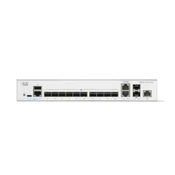
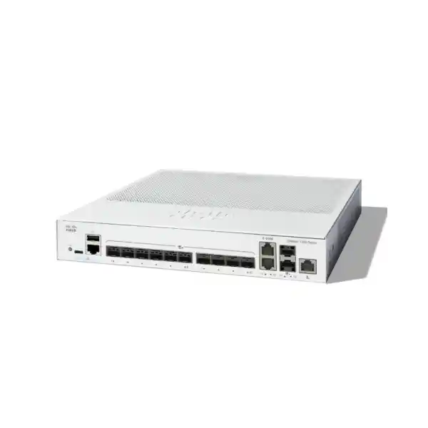
The Cisco Catalyst C1300-12XS is built for organizations that need dense 10 Gigabit Ethernet connectivity in a compact managed platform without moving to a large enterprise chassis. With ten dedicated 10G SFP+ interfaces, two additional 10G copper/SFP+ combo interfaces, a separate Gigabit Ethernet management port, 240 Gbps switching capacity and wire-speed nonblocking forwarding, it fits aggregation, server access, virtualization, high-speed storage, branch core and fiber distribution roles where predictable throughput matters. For businesses in Dubai, Abu Dhabi, Sharjah and other UAE locations, the model provides a practical bridge between traditional Gigabit access switching and modern 10G infrastructure while retaining familiar Cisco management, security and resiliency functions.
178.57 Mpps
10 x 10G SFP+
2 x 10G Combo
Hardware Stacking
Direct answer: what is the C1300-12XS designed to do?
The C1300-12XS is a fixed-configuration, fully managed 10 Gigabit Ethernet switch intended for networks that need high-speed fiber aggregation with selective 10G copper capability. Its ten native SFP+ ports suit optical uplinks, direct-attach copper links and other supported 10G SFP+ media. Two additional interface positions operate as 10G copper/SFP+ combo pairs, allowing a designer to choose either the RJ-45 or SFP+ side of each combo pair according to the physical medium required. The switch therefore supplies twelve usable 10G data interfaces when the combo interfaces are counted correctly, plus a dedicated 1 Gigabit Ethernet out-of-band management interface that is separate from normal production switching traffic.
This port architecture makes the model particularly relevant for an SMB core or aggregation layer, a compact server room, a branch distribution point, an edge data room, a small virtualization cluster, a security appliance aggregation zone, or a high-throughput network where several 10G links must converge. It can aggregate multiple Gigabit or multigigabit access switches through their 10G uplinks, attach 10G servers and storage targets, connect firewalls in high-availability pairs, or build a resilient fiber backbone between communications rooms. Unlike an unmanaged high-speed switch, the C1300-12XS includes advanced VLAN, spanning-tree, link aggregation, access-control, quality-of-service, multicast, IPv4/IPv6 routing, monitoring and authentication features needed to operate the 10G fabric as a governed business network rather than a simple high-speed bridge.
For organizations comparing architecture options, the model should be viewed as a compact managed 10G switching platform, not as a PoE access switch. It does not provide a PoE budget for powering phones, cameras or wireless access points. Those endpoints can remain on access-layer switches while the C1300-12XS carries aggregated traffic upstream at 10G. This separation can be efficient in Dubai offices and mixed-use facilities where floor switches provide copper access and PoE, while fiber trunks return to a centralized server or network room. FourTeck can align the switch with compatible optics, DAC choices, patching, rack design, VLAN planning and firewall connectivity through its broader UAE networking portfolio.
C1300-12XS hardware and performance profile
The 240 Gbps switching figure corresponds to full-duplex line-rate treatment of the twelve 10G data interfaces: each 10G port can transmit and receive simultaneously, so aggregate fabric capacity is evaluated in both directions. The published forwarding rate of 178.57 million packets per second for 64-byte traffic shows that Cisco specifies the platform for wire-speed, nonblocking operation. This matters in designs where traffic is not merely large sequential file transfer. Firewalls, virtual machines, storage workloads, telemetry collectors and east-west application flows can create many small packets, and packets-per-second capability becomes as important as headline bandwidth.
A 3 MB packet buffer is provided for this model. Buffer capacity should never be interpreted as a substitute for capacity planning, because sustained oversubscription cannot be solved simply by storing more packets. It is nevertheless relevant during microbursts, output contention and traffic transitions where several ingress flows momentarily converge on one egress interface. Good design pairs the hardware buffer with appropriate QoS classes, egress shaping where needed, balanced link aggregation and sensible uplink ratios. In a server or storage environment, interface utilization and queue behavior should be monitored after commissioning rather than assuming that every 10G connection will behave identically.
Cisco specifies up to 32,000 MAC entries for Catalyst 1300 10 Gigabit Ethernet SKUs. That scale is useful when the switch sits above multiple access domains, virtual hosts or dense endpoint networks. A large MAC table reduces the likelihood of unnecessary unknown-unicast flooding as Layer 2 adjacency grows. At the same time, network architects should resist extending enormous broadcast domains merely because the hardware can learn many addresses. VLAN segmentation, Layer 3 boundaries, access policies and failure-domain control remain important for performance, security and troubleshooting.
Cisco publicly documents the forwarding capacity and functional behavior but does not identify a specific merchant-silicon or ASIC part number for the C1300-12XS in its current public datasheet. Accordingly, procurement decisions should be based on the verified platform specifications rather than assuming an undocumented ASIC family. What can be stated confidently is that the switch provides hardware-based wire-speed Layer 2 forwarding and IPv4/IPv6 routing functions within the capacities published for the 10G Catalyst 1300 class.
Port map, media strategy and 10G design implications
The physical media mix is one of the strongest reasons to select the C1300-12XS. Ten ports are 10 Gigabit SFP+ interfaces. These can support appropriate optical transceivers or other compatible SFP+ media according to the required cable type, reach and link design. In many UAE facilities, this is attractive for fiber backbones between telecom rooms, server rooms and adjacent buildings, especially where electromagnetic interference, distance, cable containment or isolation makes fiber preferable to copper. SFP+ also allows a procurement team to standardize the switch while selecting different transceiver types per link rather than replacing the switching platform when media requirements vary.
The remaining two data interfaces are 10G copper/SFP+ combo ports. A combo port represents two physical connector options sharing one logical interface resource. For each combo pair, the network uses either the RJ-45 10GBASE-T side or its associated SFP+ side, not both simultaneously as independent data ports. This distinction is essential when counting capacity and producing bills of materials. A correct BOM for twelve active data links can therefore include ten SFP+ links plus two copper links, or twelve SFP+ links when the two combo ports are used in fiber mode, or another valid mix that respects the paired nature of the connectors.
10GBASE-T can simplify short server-room connections where existing structured Category 6A cabling and RJ-45 patching are already present. SFP+ direct-attach copper can be useful for very short in-rack connections when supported by the equipment at both ends, while optical SFP+ is usually preferred for longer runs and electrically isolated links. The correct choice depends on distance, transceiver support, power consumption, rack geography, cable bend radius, structured cabling standards and the interfaces available on the connected firewall, server, storage device or access switch.
The separate Gigabit Ethernet management port is operationally important. It permits out-of-band management designs in which switch administration is separated from the production data plane. A small management network can be connected to console servers, jump hosts, monitoring systems or a dedicated management switch. During a production VLAN or routing incident, administrators can retain a path to the C1300-12XS that does not depend on the affected data VLANs. For organizations implementing stronger operational security, this management separation can be combined with SSH, HTTPS, RADIUS or TACACS+ and management ACLs.
When planning optics, verify exact Cisco compatibility and reach requirements at quotation stage. Do not order transceivers simply because the connector shape is SFP+. Fiber type, wavelength, distance, connector standard, link partner capability and supported module matrix must all align. FourTeck’s UAE IT services team can assist with rack surveys, fiber-path evaluation, interface mapping and implementation planning so the switch is quoted as part of a working link design rather than as an isolated box.
Layer 2 switching: VLANs, loop prevention and resilient uplinks
At Layer 2, the C1300 family supports the controls expected in a managed business network. VLAN capabilities include port-based and IEEE 802.1Q tag-based VLANs, MAC-based VLANs, protocol-based VLANs, IP-subnet-based VLANs, management VLANs, private VLANs, guest and unauthenticated VLANs, dynamic VLAN assignment through RADIUS, and several service-provider-oriented functions. Cisco specifies support for up to 4094 VLAN identifiers, with a range reserved internally. This broad feature set means the switch can separate users, servers, voice, cameras, guest networks, management interfaces, hypervisor traffic, storage networks and security zones according to policy instead of physical port location alone.
Spanning-tree support includes classic IEEE 802.1D STP, Rapid Spanning Tree based on 802.1w, Multiple Spanning Tree based on 802.1s, and Cisco-oriented PVST+ and Rapid PVST+ behavior. The value is not simply protocol compatibility; it is controlled redundancy. A fiber aggregation switch often has multiple uplinks and may be connected to downstream switches through redundant physical paths. Without loop prevention, accidental Layer 2 loops can cause broadcast storms and rapid service degradation. RSTP improves convergence compared with classic STP, while MSTP can map groups of VLANs into spanning-tree instances for a more scalable topology.
Link aggregation uses IEEE 802.3ad LACP. Cisco documents up to eight groups with up to eight ports in each group for dynamic link aggregation. Aggregation can increase logical link capacity and provide physical-path resilience when the connected peer supports a compatible bundle. It is especially useful for connecting an access switch stack, server with multiple interfaces, storage appliance, firewall cluster design or another aggregation switch. Traffic distribution still depends on hashing behavior, so a single flow typically does not become faster than one physical 10G member merely because several 10G links are placed in a LAG. The benefit comes from spreading multiple flows and maintaining connectivity when a member link fails.
Private VLAN and protected-port functions allow isolation between devices that share higher-level addressing or service infrastructure. This can be helpful in hospitality, shared offices, labs, managed service environments or infrastructure networks where endpoints require common upstream connectivity but should not freely communicate with each other. Q-in-Q and selective Q-in-Q capabilities also broaden the model’s role for service-provider-style or campus transport designs where customer VLAN tags must be carried across an intermediate switched domain.
Features such as UDLD and independent loopback detection add protection for situations where a physical fault or incorrect wiring creates abnormal forwarding behavior. In fiber networks, unidirectional conditions can be especially confusing because one optical direction may fail while the other appears operational. The combined use of physical monitoring, UDLD, spanning tree and well-documented redundant topology improves the ability to contain these failure modes before they become wider outages.
Layer 3 routing and when to route on the switch
The C1300-12XS is not limited to Layer 2 switching. Cisco’s 10G Catalyst 1300 specifications include wire-speed IPv4 and IPv6 routing, configuration of Layer 3 interfaces on physical ports, link-aggregation groups, VLAN interfaces and loopback interfaces, support for Classless Interdomain Routing, RIP version 2, policy-based routing, DHCP server functions, Layer 3 DHCP relay and UDP relay. For the 10G Catalyst 1300 class, Cisco publishes a substantially larger route and interface scale than on the 1G models, including up to 7168 combined dynamic and static IPv4 routes and up to 256 IP interfaces.
This enables practical inter-VLAN routing in a compact core. For example, separate VLANs can be created for corporate users, servers, voice devices, surveillance, wireless infrastructure, guest access and management. Switched virtual interfaces can then provide default gateways for selected VLANs, allowing traffic between permitted internal networks to be forwarded locally at wire speed instead of forcing every internal packet through an external router. That design can reduce bottlenecks and preserve firewall capacity for flows that actually require security inspection or WAN traversal.
Whether routing belongs on the C1300-12XS or on a firewall depends on policy. A security-first design may route sensitive VLANs through a next-generation firewall to enforce application control, intrusion prevention or advanced segmentation. A performance-oriented campus design may route trusted east-west traffic on the switch and send only north-south or restricted flows to the firewall. Policy-based routing can add selective next-hop control based on ACL matches, but it should be used deliberately because complex PBR policies increase troubleshooting requirements and may interact with firewall asymmetry or high-availability behavior.
A critical product-selection detail is OSPF. Cisco documents OSPF v2 and v3 for Catalyst 1300X SKUs only. The C1300-12XS belongs to the Catalyst 1300 10G family, not the 1300X family, so buyers should not assume OSPF capability on this model. If OSPF is mandatory for dynamic campus routing, the architecture should be revised around a supported platform or an upstream router/firewall. RIP v2 and static routing remain available for simpler dynamic and deterministic designs.
In many Dubai SMB and midmarket networks, the routing requirement is straightforward: default routes toward redundant firewalls, static internal routes, VLAN interfaces and DHCP relay toward centralized servers. The C1300-12XS can handle this role effectively while preserving high-speed switching. For larger networks with complex routing domains, extensive dynamic protocols, EVPN/VXLAN fabrics or enterprise campus automation requirements, a higher Cisco switching family may be more appropriate.
Security controls for a 10G aggregation layer
High-speed switching must be paired with control. The C1300 platform supports IEEE 802.1X authentication, RADIUS accounting, dynamic VLAN assignment, MAC authentication and web-based network admission functions. In an access-oriented use case, 802.1X allows a port to require authentication before normal network access is granted. In an aggregation role, the same standards-based security framework helps maintain consistent operational policy across the network, while RADIUS and TACACS+ can centralize administrator or endpoint authentication depending on the implementation.
DHCP snooping, IP Source Guard and Dynamic ARP Inspection form an important set of Layer 2 protections. DHCP snooping identifies trusted and untrusted DHCP paths so rogue DHCP replies can be blocked. The learned binding information can support IP Source Guard, which rejects traffic when the source addressing does not match permitted or learned bindings. Dynamic ARP Inspection validates ARP behavior against expected IP-to-MAC relationships, reducing opportunities for common local man-in-the-middle techniques. These mechanisms are most effective when VLANs, trusted uplinks and endpoint-facing ports are classified correctly during deployment.
Spanning-tree BPDU Guard, Root Guard and loopback protection defend the topology itself. BPDU Guard can shut an edge port when unexpected bridge protocol traffic appears, helping stop accidental or unauthorized switches from changing the Layer 2 topology. Root Guard protects the intended root-bridge position. Port security can restrict learned MAC addresses, while private VLANs and protected ports limit direct Layer 2 communication between endpoints. Storm control provides rate governance for broadcast, multicast and unknown-unicast conditions that could otherwise consume bandwidth across the switching domain.
Access control lists on Catalyst 1300 10G SKUs scale to as many as 2048 rules according to Cisco’s platform table. Matching can consider source and destination MAC address, VLAN identifier, IPv4 or IPv6 address, protocols, ports, DSCP, IP precedence, TCP or UDP ports, 802.1p priority, Ethernet type, ICMP, IGMP and TCP flags. ACLs can be applied on ingress and egress, and time-based rules are supported. This makes the switch useful for enforcing coarse-grained infrastructure policy close to the forwarding plane, such as limiting management traffic to administrative subnets or restricting selected inter-VLAN flows.
Management security includes SSH, SCP and HTTPS, plus role/privilege controls and central authentication options. Cisco also describes Secure Core Technology, Secure Sensitive Data handling, run-time defenses, chip guard and boot-integrity visibility. These platform protections are useful, but they do not remove the need for operational hardening. Default credentials must be changed, unused services disabled, management protocols restricted, firmware maintained, administrative networks isolated and configuration backups stored securely.
A firewall remains the correct control point for advanced threat prevention, application visibility, VPN termination and Internet perimeter policy. The switch complements that security architecture by protecting local network behavior and reducing trivial Layer 2 attacks before traffic ever reaches the firewall. FourTeck’s dedicated Firewall Dubai practice can align switch VLANs, LAGs and routing boundaries with firewall HA pairs and security zones.
Hardware stacking: scale, resiliency and design boundaries
Cisco supports hardware stacking on the C1300-12XS and lists the model within the Catalyst 1300 Family 2 stacking group. Current Cisco documentation allows up to eight compatible switches in a stack and describes front-panel stacking with a single management identity, hardware failover, active/standby control, automatic numbering, hot-swap behavior, ring or chain topologies and link aggregation across multiple units. This is significantly different from simply clustering several independently managed switches in a dashboard. A hardware stack is intended to operate as one logical system for administration and resiliency.
The C1300-12XS stacks using high-speed 10 Gigabit Ethernet fiber interfaces. That design provides flexibility because front-panel ports can serve as stack interconnects without requiring a proprietary rear stacking module. The architectural trade-off is that every interface dedicated to stacking is an interface not available for ordinary network traffic, so capacity calculations must include the stack topology. A two-switch ring, for example, requires enough interfaces and cabling to maintain the desired resilient path while still leaving sufficient 10G ports for production uplinks, servers and firewalls.
Stack members must belong to the compatible Cisco family grouping. Cisco explicitly states that product IDs from the same family can be stacked together and that cross-stacking between families is not supported. Therefore, a future expansion plan should not assume that every Catalyst 1300 or 1300X SKU can join an existing C1300-12XS stack. This is one reason to document expected port growth before the initial purchase. If an organization is likely to require substantially more copper 10G, more SFP+ density or PoE access in the same logical stack, member compatibility and interface economics should be reviewed before standardizing on a model.
A stack can improve operations by presenting one control point, supporting fast failover and permitting LAGs that span members. A downstream device with two links can connect one link to each stack member, reducing the impact of a single switch failure while retaining a single logical port channel. This is valuable for important access switches, virtual hosts and firewall appliances that support suitable LACP designs. Physical resilience still depends on power, cabling and location. Two stacked switches mounted in the same rack and connected to the same UPS do not protect against every facility-level failure.
For mission-critical deployments, consider separate power sources where possible, redundant UPS capacity, diverse fiber paths, clear stack-role documentation and configuration backups. Monitor the stack for member health and link errors rather than treating stacking as automatic high availability. Resiliency is a system property created by the switch, the power design, the link topology, the connected peers and operational procedures working together.
QoS, storage traffic and congestion engineering
The C1300 family provides eight hardware queues, strict-priority and Weighted Round-Robin scheduling, classification based on port, 802.1p, IPv4/IPv6 precedence, ToS and DSCP values, and mechanisms for classification, remarking, policing and shaping. For a 10G aggregation switch, these features are useful because several traffic classes may converge at high speed. Voice signaling, real-time media, storage, server replication, backup, CCTV, user traffic and Internet-bound sessions can all share physical links even when they remain logically separated by VLAN.
QoS policy should begin with a traffic model rather than a desire to mark everything as important. Strict-priority queues are appropriate only for genuinely latency-sensitive classes and must be policed or bounded so they cannot starve other traffic. Weighted scheduling can preserve service for lower-priority classes during contention. DSCP trust boundaries should be defined carefully: a server or endpoint should not automatically be allowed to label bulk traffic as the highest priority unless that behavior is controlled. At access boundaries, remarking or classification may be safer than blind trust.
Cisco also documents iSCSI traffic optimization. That can be relevant when the switch is used between servers and IP storage, but successful storage networking still requires end-to-end design. MTU configuration, flow paths, link aggregation behavior, NIC teaming, multipathing, target performance and backup windows all affect results. The C1300-12XS supports jumbo frames up to 9000 bytes, while Cisco lists a lower default MTU. Jumbo frames should therefore be configured consistently across every device in the path if the application requires them. An inconsistent MTU can create difficult intermittent failures rather than an obvious outage.
Ingress policing and egress shaping are useful when a faster source feeds a slower destination or when a customer, tenant or service should be restricted to a defined throughput. Flow-based control can prevent one workload from consuming a shared uplink. Yet queue statistics and real utilization should be measured after deployment. A 10G interface that appears lightly utilized over a five-minute average may still experience microbursts that fill buffers and cause drops. Monitoring at shorter intervals or using flow telemetry helps reveal these patterns.
For workloads that are truly loss-sensitive or demand data-center-class features beyond the C1300 portfolio, validate requirements before purchase. The correct question is not simply whether the switch has 10G ports; it is whether its buffering, QoS, routing, telemetry and redundancy features meet the application’s service objectives. This is especially important for storage, media production, financial applications and virtual desktop infrastructure where performance expectations are measurable and business-critical.
Management, monitoring and lifecycle operations
A switch remains reliable only when it can be observed and maintained. The Catalyst 1300 platform supports browser-based management, full and menu-based CLI access, SSH, HTTPS, SNMP-oriented management functions, syslog, RMON, port mirroring, VLAN mirroring, RSPAN, sFlow export, configuration file transfer, SCP, TFTP, ping, traceroute, SNTP and cable diagnostics. These options let a small IT team begin with an intuitive web interface while allowing experienced administrators to use scriptable CLI and centralized monitoring as the network grows.
sFlow can export sampled traffic information to an external collector, giving visibility into which hosts and conversations are consuming capacity. This is valuable on 10G aggregation links where interface counters alone reveal that a port is busy but not which workloads are responsible. RSPAN extends packet-mirroring workflows across a Layer 2 domain, while local port or VLAN mirroring helps troubleshooting teams capture traffic with an analyzer. These tools can shorten incident diagnosis when performance problems, packet loss, unexpected broadcasts or security events must be investigated.
Cisco supports dual firmware images, which improves resilience during upgrade workflows. Firmware can be upgraded through supported web or transfer mechanisms, and configuration files can be copied and edited to assist repeatable deployments. A production change process should still include a saved configuration, release-note review, maintenance window, rollback plan and validation checklist. In a hardware stack, firmware consistency and stack-member behavior should be checked as part of the same workflow rather than upgrading units ad hoc.
Auto Smartports and discovery functions can simplify edge configuration by recognizing connected device types through Cisco Discovery Protocol or LLDP-MED and applying appropriate policy. In a core or aggregation deployment, experienced teams may prefer explicit configuration and templates because the attached devices are infrastructure components rather than arbitrary endpoints. Both approaches are legitimate; what matters is that automated behavior is understood and does not create unexpected VLAN or QoS assignments.
Operational documentation should record interface purpose, fiber path, optic type, LAG membership, VLAN trunks, allowed VLAN lists, native VLAN handling, routed interface addressing, default routes, ACLs, authentication servers, NTP, syslog destinations, monitoring addresses, stack member roles and software version. This may seem administrative, but it converts a switch from a collection of configuration lines into maintainable infrastructure. When a link fails months later, clear records reduce dependence on individual memory.
For managed deployments, FourTeck can integrate switching with monitoring, rack organization, firewall connectivity and server-room operations. The Server Dubai practice is particularly relevant when the C1300-12XS will aggregate virtualization hosts, storage appliances or rack-mounted server infrastructure that require coordinated NIC, VLAN and uplink design.
Physical format, power, acoustics and UAE environmental considerations
The C1300-12XS measures approximately 268 mm wide, 300 mm deep and 43.94 mm high, with a published unit weight of about 2.67 kg. The height corresponds to a compact 1U-class profile, while the chassis is narrower than a conventional full-width 19-inch switch. Cisco lists the model as rack-mountable, but procurement teams should confirm the exact mounting accessories required for the intended cabinet because package-mounting contents can vary by model class. Rack depth, side clearance, cable management and power-cord routing should be considered together rather than checking only the switch width.
The switch uses an internal universal 100–240 V AC, 50–60 Hz power supply. Cisco’s power table lists approximately 24.3 W maximum system power consumption at 110 V and 26.1 W at 220 V for the C1300-12XS, with a lower idle consumption figure around 11.5 W at 220 V. Actual draw depends on operating conditions and connected media. Because the model does not provide PoE, its electrical demand is much lower than large PoE access switches. Nevertheless, rack UPS sizing should include switch load, firewalls, routers, servers, storage and any redundant power equipment rather than treating each device independently.
Cisco specifies one fan for the C1300-12XS and publishes an acoustic figure of approximately 29.5 dBA at 25°C, together with an MTBF figure exceeding 1.2 million hours at 25°C. MTBF is a statistical reliability measure, not a guarantee that a particular unit will operate for that duration. Temperature, dust, airflow, power quality and maintenance practices remain important. A low acoustic level can make the model suitable for compact network rooms, but a proper communications cabinet should still provide ventilation appropriate to the total thermal load.
The documented operating temperature range for this model is -5°C to 50°C, with a minimum 0°C ambient for cold start. Storage temperature is published as -25°C to 70°C, and relative humidity is 10% to 90% noncondensing. UAE deployments require particular attention to air conditioning and dust control. Outdoor summer temperatures can far exceed the switch’s operating range, so the device should not be treated as an outdoor or unconditioned-equipment-room platform. A building’s nominally air-conditioned environment is also not enough if a closed cabinet traps heat after hours or if cooling depends on a single unit without alarm monitoring.
Fiber transceivers themselves generate heat, and a chassis with many populated SFP+ cages can operate differently from a lightly loaded laboratory setup. Cable bundles should not obstruct intake or exhaust paths. Where cabinets are densely packed, blanking panels, vertical cable managers and thoughtful device placement can improve airflow. In critical sites, environmental sensors should alert administrators to temperature and humidity excursions before equipment begins failing.
Cisco lists certifications including UL 62368, CSA 22.2, CE marking and FCC Part 15 Class A for the family. Regional procurement should still verify the exact commercial SKU, power cord option, warranty channel and import/distribution requirements for UAE use at the time of order.
Deployment topology 1: compact SMB core and aggregation
A common deployment places the C1300-12XS at the center of several access switches. Each floor or department may use a 24- or 48-port Gigabit/PoE switch for PCs, phones, cameras and access points. Those switches connect to the C1300-12XS over 10G SFP+ fiber. The C1300-12XS then connects to a firewall pair, server infrastructure and possibly an upstream WAN router. This design keeps endpoint switching economical while preventing 1G uplinks from becoming bottlenecks as user and wireless traffic grows.
A pair of C1300-12XS units can be stacked to improve availability. Access switches can build LACP port channels with one member link terminating on each stack member, assuming the downstream model and topology support it. Firewall connections can similarly use redundant physical interfaces according to the firewall vendor’s recommended HA and aggregation design. The stack can route selected internal VLANs while sending Internet and protected-zone traffic toward the firewall.
This model is especially attractive when the access layer already has 10G SFP+ uplinks. Twelve 10G interfaces can support several access-switch trunks while reserving ports for servers and security infrastructure. Capacity should be modeled explicitly. If eight access switches each send a 10G uplink into one core, two interfaces connect to a firewall pair and two are consumed by stack interconnection, the port count is effectively full. Future growth may therefore justify a larger 10G model even if today’s link count fits exactly.
The design should also consider failure domains. If all access switches depend on a single C1300-12XS, that device is a central point of failure despite redundant access uplinks elsewhere. Stacking, redundant power infrastructure and alternative paths can address this. The correct architecture is shaped by the cost of downtime, not simply by the cost of a second switch.
Deployment topology 2: server, virtualization and storage aggregation
In a compact server environment, the C1300-12XS can aggregate 10G NICs from virtualization hosts, backup servers, NAS systems and security appliances. SFP+ is well suited to short DAC links inside a rack when compatibility is confirmed, while optical links can connect equipment across rows or rooms. The two 10GBASE-T combo options are useful when specific servers or appliances expose RJ-45 10G interfaces rather than SFP+.
Virtualization increases the importance of logical segmentation because one physical server may host workloads from many application tiers. Separate VLANs can be assigned for hypervisor management, virtual-machine production traffic, storage, backup, replication and migration. LACP or host-side teaming may provide redundancy, but the exact method should follow the hypervisor vendor’s support model. Some storage protocols prefer multipathing rather than link aggregation, and conflating those mechanisms can produce a design that works during normal operation but fails badly during a path outage.
The switch’s jumbo-frame capability can reduce protocol overhead for selected storage workloads, but only if the entire path supports a consistent MTU. Verify server NIC, virtual switch, storage target, VLAN interface and any routed hop. If one element remains at a smaller MTU and discovery does not behave as expected, applications may exhibit retransmissions, stalls or fragmented traffic. Therefore, a change to jumbo frames should be implemented as a controlled end-to-end design rather than a switch-only toggle.
Traffic monitoring is equally important. Backup jobs often run outside working hours and can saturate links that appear underutilized during the day. Replication traffic may be bursty and compete with user-facing services. sFlow, interface counters and queue statistics should be collected by a monitoring platform so operations teams can distinguish normal scheduled load from abnormal congestion. QoS can then be applied based on observed behavior rather than assumptions.
For larger virtualization clusters, evaluate port density carefully. Twelve 10G data ports can disappear quickly when each physical host uses two or four redundant 10G links. A model with more SFP+ capacity may have a lower total cost than deploying multiple small switches solely to gain ports. The C1300-12XS is strongest when compact density, flexible media and managed 10G aggregation match the actual host count.
Deployment topology 3: firewall aggregation and security zones
A firewall deployment may require multiple 10G interfaces for LAN, DMZ, server, WAN handoff and HA-related connectivity. The C1300-12XS can act as a controlled switching layer around that firewall infrastructure, especially when external circuits or internal distribution links arrive on fiber. VLAN trunks can carry several security zones over fewer physical links where the firewall architecture allows tagged subinterfaces, or physical interfaces can remain dedicated to separate zones where policy or compliance requires stronger separation.
A key design principle is symmetry. Stateful firewalls expect traffic for a session to follow a predictable path. If policy-based routing, inter-VLAN routing or redundant LAGs are configured without regard to firewall HA behavior, traffic can enter through one node and return through another path, causing session drops. The switching and firewall topology must therefore be engineered as one system. Default routes, static routes, VLAN gateways, HA virtual addresses, link monitors and aggregation settings should be documented together.
For Internet perimeter zones, the switch’s ACL and Layer 2 security controls can provide additional guardrails but should not be used as a replacement for firewall inspection. An ACL can restrict which management sources reach infrastructure, or limit unnecessary cross-zone traffic before it reaches another device. DHCP snooping and ARP protections can reduce local spoofing risks in internal segments. The firewall remains responsible for deep inspection, user or application policy, VPN, threat detection and external exposure.
Where an organization operates multiple security appliances, the C1300-12XS can also simplify migrations. Old and new firewalls can be connected simultaneously during a controlled cutover, with VLAN trunks or routed links moved according to a migration plan. High 10G port density reduces the temptation to perform unsafe cable swaps under time pressure. A prepared rollback path and labelled patching are as important as the switch configuration itself.
Multicast, voice and service traffic
Cisco includes IGMP snooping for versions 1, 2 and 3, IGMP querier functionality, IGMP proxy capability, source-specific multicast support and Multicast VLAN Registration features in the Catalyst 1300 portfolio. On 10G models, the platform supports a larger multicast-group scale than 1G members of the family. These controls matter whenever surveillance video, IPTV, market-data feeds, imaging, media distribution or other one-to-many applications are present.
Without snooping, Layer 2 multicast can resemble broadcast behavior and consume bandwidth on ports that never requested the stream. IGMP snooping listens to group membership and limits forwarding to interested recipients. A querier is necessary within a Layer 2 multicast domain if no multicast router is performing that role. Configuration should therefore define where the querier resides and avoid accidental competing queriers or inconsistent timers.
Voice VLAN support can automatically place recognized voice endpoints into a dedicated VLAN and apply suitable QoS treatment. LLDP-MED and Cisco Discovery Protocol assist endpoint discovery. Even though the C1300-12XS itself is not normally the endpoint access switch for desk phones, voice VLANs may traverse its trunks from downstream PoE access switches. QoS trust and remarking behavior should remain consistent end to end so voice packets retain intended priority through aggregation rather than losing classification at a trunk boundary.
Video surveillance is similar. Camera access switches may feed several high-bitrate streams into 10G aggregation. Average utilization can look modest until many cameras transmit simultaneously or a recorder pulls archived footage while live streams continue. VLAN separation, multicast optimization where applicable, uplink sizing and storage capacity should be designed together. The switch provides the forwarding tools, but application behavior determines the traffic engineering.
UAE procurement and bill-of-material sizing methodology
A successful quote begins with port purpose, not a model number. List every 10G connection required on day one: access-switch uplinks, firewall links, servers, storage, WAN devices, stack links, test or monitoring ports and spare capacity. Mark the physical medium for each link. If a device requires 10GBASE-T, reserve one of the two copper-capable combo ports. If it requires SFP+, determine whether the link will use optical transceivers or DAC. Then add realistic growth capacity rather than leaving zero spare interfaces immediately after installation.
Next, map redundancy. A single logical connection may consume two physical ports when LACP, NIC teaming or dual-path design is used. A two-member stack consumes ports for interconnection. A firewall HA pair can consume more links than a standalone firewall. A storage array may need separate paths per controller. Port-count mistakes often occur because procurement teams count devices rather than physical interfaces. The correct BOM counts every cable endpoint and recognizes that combo ports provide media choice, not double port density.
Optics are a separate design line. Identify fiber type, connector, link distance and optical budget. A short multimode run inside a building has different transceiver requirements from a long single-mode link between buildings. Verify supported modules on both ends. A transceiver compatible with the switch may still be unsuitable for the remote device or fiber plant. Patch cords, couplers, patch panels and cleaning tools should be included where relevant, because a 10G optical link is only as reliable as the complete optical path.
Power and rack accessories also belong in the BOM. Confirm UAE-compatible power cords, UPS capacity, rack mounting, cable managers, labeling and environmental monitoring. If the device will sit in a shallow wall cabinet, verify the 300 mm chassis depth plus connector and cable bend allowance. Fiber patch cords require gentle bend radius and should not be forced against a cabinet door. RJ-45 10G patching also benefits from high-quality Category 6A cabling and proper termination.
Software and support should be reviewed at quotation time. Cisco positions the Catalyst 1300 family with embedded management and a limited lifetime hardware warranty with return-to-factory replacement, together with specified support access. Exact warranty handling, local logistics and optional service coverage can vary by commercial channel and region, so the quote should state what is included rather than relying on generic assumptions. Mission-critical networks may require enhanced replacement or support terms beyond the base warranty.
Finally, document the target software version and configuration scope. A switch delivered in a box is not the same as a production-ready switch. Deployment may include firmware update, VLAN creation, trunking, LAGs, routing, ACLs, authentication, syslog, SNMP/monitoring, NTP, management addressing, backups, labels and acceptance testing. Including these tasks in the procurement plan produces a more accurate project cost and avoids treating engineering as an afterthought.
Licensing and software positioning
The Catalyst 1300 family is aimed at small and medium business switching and is designed around an integrated feature set rather than the licensing model commonly associated with larger Cisco enterprise campus platforms. For many buyers, this simplifies deployment because core switching, routing, security and management functions are available as platform capabilities. Nevertheless, a purchase should always be validated against the current Cisco ordering guide and desired support service because cloud management, support entitlements or future software capabilities may have separate commercial conditions.
The most important licensing question is functional fit. If the requirement is VLAN switching, LACP, spanning tree, static and RIP routing, ACLs, 802.1X, RADIUS/TACACS+, DHCP security, QoS, stacking, web management, CLI and standard monitoring, the C1300-12XS aligns well. If the requirement includes OSPF specifically, Cisco’s current specification limits OSPF to 1300X SKUs, so this model should not be selected on the assumption that a license will unlock unsupported routing behavior. Similarly, features such as enterprise fabric automation, advanced campus telemetry or large-scale dynamic routing belong in another product-selection discussion.
Firmware maintenance remains an operational responsibility even when no recurring feature license is required. Security fixes, interoperability changes and bug corrections are delivered through software updates. IT teams should maintain an asset register with serial numbers, firmware versions, installation dates, rack positions and support details. A scheduled review cycle helps avoid the common situation in which access switches and firewalls are maintained but the aggregation layer runs an old image for years because it appears stable.
When comparing quotations from different suppliers, ensure the comparison is like-for-like: exact C1300-12XS model, genuine Cisco hardware, correct regional power options, compatible optics, mounting accessories, warranty channel and implementation scope. A lower line-item switch price can become more expensive if essential transceivers, support or engineering work are omitted.
When the C1300-12XS is the right choice—and when it is not
Strong fit
Choose the C1300-12XS when the network needs a compact managed switch with predominantly SFP+ 10G connectivity, a small number of 10GBASE-T links, hardware stacking, inter-VLAN routing and serious Layer 2 security. It is well suited to small server rooms, SMB cores, branch aggregation, firewall distribution, virtualization pods and fiber-heavy campuses where twelve 10G data interfaces are enough with a reasonable growth margin.
It is also attractive when operational simplicity matters. Browser management, CLI, discovery, sFlow, RSPAN and standard authentication mechanisms provide a balanced toolset for organizations that have professional IT requirements but do not need the complexity or cost profile of a large modular campus platform.
Consider another platform
Use a different model when endpoint PoE is required on the same switch, when far more than twelve 10G data interfaces are needed, when many native 10GBASE-T ports are necessary, or when advanced dynamic routing such as OSPF on this exact SKU is mandatory. Larger 10G Catalyst 1300 members may offer better port economics for higher density, while other Cisco families may be better suited to enterprise campus routing, automation or high-availability requirements.
Also reconsider the design if every port would be occupied immediately. Running a switch at full physical port count from day one leaves no easy capacity for troubleshooting, temporary migrations or business growth. A model with spare interfaces can be operationally cheaper even if its initial hardware price is higher.
Technical specification summary for quotation review
| Model | Cisco Catalyst C1300-12XS |
| 10G SFP+ ports | 10 dedicated SFP+ plus 2 SFP+ options paired with combo 10G copper interfaces |
| 10G copper | 2 x 10GBASE-T copper, each operating as a combo with an associated SFP+ interface |
| Management port | 1 x Gigabit Ethernet out-of-band management port |
| Switching capacity | 240 Gbps |
| Forwarding rate | 178.57 Mpps at 64-byte packets |
| Packet buffer | 3 MB |
| MAC scale | Up to 32,000 entries/rules for Catalyst 1300 10G class |
| Jumbo frames | Up to 9000 bytes |
| IPv4 route scale | Up to 7168 dynamic + static routes for Catalyst 1300 10G class |
| IP interfaces | Up to 256 for Catalyst 1300 10G class |
| Routing | Static IPv4/IPv6, RIP v2, PBR, DHCP relay; OSPF is not specified for this non-1300X model |
| Stacking | Hardware stacking supported; up to 8 compatible switches, same family grouping required |
| Dimensions | 268 x 300 x 43.94 mm (W x D x H) |
| Weight | Approximately 2.67 kg |
| Power input | 100–240 V AC, 50–60 Hz, internal universal supply |
| Max system power at 220 V | Approximately 26.1 W |
| Fan/acoustics | 1 fan; approximately 29.5 dBA at 25°C |
| Operating temperature | -5°C to 50°C; minimum 0°C ambient for cold start |
| Warranty | Cisco limited lifetime warranty with return-to-factory replacement, subject to applicable terms |
Implementation sequence for a production deployment
A disciplined deployment starts before the switch is powered on. Record the model and serial number, inspect the chassis and accessories, verify the correct UAE power cord, identify rack location and confirm the optic and cable list. Label every planned link at both ends. For a stack, decide physical member order, stack topology and which ports will be consumed by stacking before production cables are connected.
After initial access, change administrative credentials and establish a dedicated management address. Configure secure management protocols, time synchronization, syslog and monitoring destinations. If RADIUS or TACACS+ will be used, retain a tested local recovery account according to policy. Restrict management access to appropriate source networks. Back up the baseline configuration before moving into production changes.
Build VLANs and trunks from a documented matrix. Avoid allowing every VLAN on every trunk simply because it is convenient; explicit allowed-VLAN lists reduce accidental propagation and make troubleshooting easier. Configure LACP bundles and verify that both ends agree on member state, speed and VLAN treatment. Apply spanning-tree edge settings only to true edge ports, not to infrastructure trunks. Configure root priorities intentionally so the aggregation layer behaves predictably during topology changes.
If the switch will route, create Layer 3 interfaces, addressing, static or RIP routes, relay services and ACLs in a staged manner. Test one VLAN or route class at a time. Confirm that firewall return routes exist before moving gateways. Check for asymmetric paths. For IPv6, apply equivalent policy rather than assuming IPv4 ACLs automatically protect IPv6 traffic.
Enable DHCP snooping, DAI and IP Source Guard only after trusted uplinks and endpoint ports are mapped correctly. These features can improve security dramatically but can also disrupt legitimate service when bindings or trust states are wrong. Roll them out in a controlled sequence with console or out-of-band access available.
Finally, validate performance. Check interface errors, optical diagnostics where available, negotiated speed, LAG status, spanning-tree state, MAC learning, route tables, ACL counters, queue drops and CPU or memory health. Generate representative traffic between key endpoints and verify monitoring visibility. Save the final configuration and produce an as-built record that includes port maps, VLANs, routes and support information.
This commissioning discipline is more valuable than chasing a single synthetic benchmark. A production network succeeds when faults are contained, policies behave consistently, administrators can reach devices during incidents and documentation enables repeatable support.
Migration from Gigabit aggregation to 10 Gigabit
Many organizations do not need to replace the entire access layer to benefit from 10G. The C1300-12XS can be introduced as an aggregation layer while existing Gigabit switches continue serving endpoints. Where those access switches support 10G uplinks, their uplinks can be moved to the new core one by one. This reduces disruption and creates a clear modernization path without forcing simultaneous replacement of every desk port.
Begin by measuring present uplink utilization and identifying congestion windows. A 1G uplink that frequently reaches high utilization is an obvious candidate for 10G migration. Wireless access layers serving Wi-Fi 6 or denser deployments can also create aggregate traffic that exceeds legacy uplink design assumptions even when individual client devices rarely use a full gigabit. Server and backup flows are another common driver because east-west traffic may never cross the Internet firewall and therefore be underestimated by WAN-focused monitoring.
A phased migration can preserve VLAN numbering and gateway design initially. Replace the physical uplink, validate trunking, then consider moving routing onto the new core as a separate change. Separating physical and logical migrations reduces variables during troubleshooting. If the existing core also hosts DHCP relay, STP root and management functions, transfer those roles in a planned sequence rather than changing everything in one maintenance window.
Fiber infrastructure must be audited before migration. A legacy multimode plant may support 10G only within particular distance limits and optic types. Dirty connectors, marginal splices or old patch leads that tolerated 1G can become problematic at higher speeds. Test critical links, clean connectors and record optical power where practical. The switch cannot compensate for a poor physical layer.
Once migration is complete, update diagrams and decommission unused legacy trunks. Leaving old uplinks connected but administratively disabled can create confusion months later. A clean final state—with labels, documentation and monitoring—turns the 10G upgrade into an operational improvement rather than just a bandwidth change.
Common design mistakes to avoid
Counting combo ports twice
The two RJ-45 connectors are paired with two SFP+ connectors. Each pair is one logical 10G interface choice. Do not build a BOM assuming fourteen independent 10G data ports.
Ignoring stack-port consumption
Front-panel stacking uses production-capable 10G interfaces. Reserve those ports before counting how many interfaces remain for servers, access switches and firewalls.
Assuming every 10G link is optical
The platform offers both SFP+ and combo 10GBASE-T choices, but the connected device, cabling and distance determine which medium is appropriate. Validate end-to-end compatibility.
Treating OSPF as a licensed add-on
Cisco’s published feature matrix associates OSPF with C1300X SKUs. The C1300-12XS should not be purchased on the assumption that software licensing will add an unsupported protocol.
Extending one giant VLAN
A large MAC table and strong switching capacity do not justify an oversized broadcast domain. Segment users, servers, management and services according to security and failure-domain requirements.
Skipping environmental design
UAE ambient conditions make controlled cooling essential. Do not place the switch in a sealed, unconditioned or dusty cabinet simply because its average power draw is modest.
Frequently asked technical questions
Does the Cisco C1300-12XS have twelve 10G ports?
Yes, it provides twelve usable 10G data interfaces when correctly interpreted: ten dedicated SFP+ ports and two additional combo interfaces. Each combo interface can use either its 10G copper RJ-45 connector or associated SFP+ connector, not both at once. It also has a separate Gigabit Ethernet management port.
Is the C1300-12XS a PoE switch?
No. It is a 10G aggregation and managed switching platform without a PoE power budget. Use PoE-capable access switches for phones, cameras and wireless APs, then aggregate those switches over 10G uplinks.
Can it be stacked?
Yes. Cisco lists the C1300-12XS as hardware-stackable within the compatible C1300 Family 2 grouping and supports stacks of up to eight compatible units. Front-panel 10G interfaces are used for the stacking interconnect, so plan port consumption accordingly.
Can the switch route between VLANs?
Yes. It supports wire-speed IPv4 and IPv6 routing, Layer 3 interfaces, static routing, RIP v2, PBR and relay functions. Cisco’s 10G C1300 class supports up to 7168 IPv4 dynamic-plus-static routes and up to 256 IP interfaces.
Does this model support OSPF?
Cisco’s current product specification marks OSPF v2/v3 as a feature for C1300X SKUs only. The C1300-12XS is not a C1300X SKU, so architects requiring OSPF should select a supported model or use another routing device.
What is the switching performance?
Cisco publishes 240 Gbps switching capacity and 178.57 Mpps forwarding at 64-byte packet size. The switch is specified as wire-speed and nonblocking.
Can it be used for iSCSI or virtualization traffic?
Yes, subject to workload requirements. The platform supports 10G interfaces, jumbo frames up to 9000 bytes, QoS controls and iSCSI optimization. Storage architects should still validate end-to-end MTU, multipathing, NIC behavior, oversubscription and performance objectives.
What does the dedicated management port provide?
The separate Gigabit Ethernet management interface supports out-of-band administration, allowing the management path to remain isolated from normal production VLANs. This can improve recoverability and security when paired with a dedicated management network.
Decision recap: who should shortlist the C1300-12XS?
Shortlist the Cisco Catalyst C1300-12XS when your topology is dominated by 10G SFP+ links, you need a compact managed switching footprint, and twelve 10G data interfaces provide sufficient capacity with room for stack links and growth. It is a strong fit for UAE SMB cores, branch aggregation, firewall distribution, server-room switching and virtualization environments that need wire-speed performance plus mature network controls.
Its practical strengths are the mix of SFP+ and 10GBASE-T combo media, 240 Gbps switching capacity, hardware stacking, Layer 3 routing, broad VLAN capabilities, LACP, comprehensive spanning tree, ACLs, 802.1X, DHCP snooping, DAI, IP Source Guard, QoS, sFlow and secure management. The principal design constraints are equally clear: no PoE, only two native 10G copper choices, front-panel ports consumed for stacking, and no published OSPF support on this non-1300X SKU.
A good purchase decision therefore comes from topology mapping rather than feature counting. If your links, media, routing protocol, security model and growth assumptions match this profile, the C1300-12XS delivers a focused 10G aggregation platform without overbuilding the network.
Quotation input checklist
Number of SFP+ links, number of 10GBASE-T links, expected spare ports, stack-member count and any monitoring/test interfaces.
Multimode or single-mode fiber, link lengths, connector type, patch-panel details, transceiver requirement and any DAC connections.
Connected access switches, firewall model and HA method, servers, storage systems, routers and redundancy objectives.
VLAN list, trunk design, LACP bundles, spanning-tree root plan, private VLAN requirements and multicast use cases.
VLAN gateways, static routes, RIP requirements, PBR, DHCP relay, IPv6 plans and firewall return routes.
Management IP, RADIUS/TACACS+, syslog, sFlow collector, SNMP monitoring, NTP, firmware policy, backup and support level.
FourTeck consultation and UAE deployment support
FourTeck can supply the Cisco Catalyst C1300-12XS as part of a complete Dubai and UAE network solution covering switch selection, compatible optic planning, structured fiber integration, firewall topology, rack installation, VLAN design, routing, security hardening, monitoring and acceptance testing. The objective is to deliver a correctly sized 10G switching system rather than a standalone device whose surrounding optics, cables or configuration are left unresolved.
For a precise quotation, share the number of connected switches, servers and security appliances; required fiber distances; preferred redundancy model; whether stacking is required; current VLAN and IP plan; and whether the project includes migration from an existing core. This information allows the BOM to include the correct transceivers, patching and engineering scope and reduces last-minute changes during installation.
Organizations with multi-site or cross-border requirements can also coordinate broader infrastructure sourcing through FourTeck Global, while UAE-local design and commissioning can remain aligned with the Dubai project team.

Reviews
There are no reviews yet.