
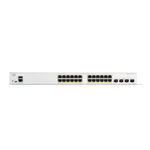
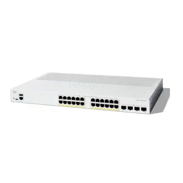
Cisco Catalyst C1300-24P-4G Network Switch
The Cisco Catalyst C1300-24P-4G is a 24-port Gigabit Ethernet PoE+ managed switch with four 1 Gigabit SFP uplinks, a 195W PoE power budget, Layer 2 switching, Layer 3 IPv4 and IPv6 routing features, strong access-security controls, advanced QoS, IPv4/IPv6 management and a fanless 1RU design. It is intended for organizations that need enterprise-style network control without moving to an unnecessarily complex or over-sized access platform.
Choose this model when the access layer needs up to 24 powered Gigabit endpoints, roughly 195W of total PoE capacity and dedicated 1G fiber uplinks. If your design needs 10G uplinks, full-power PoE on many ports at once or hardware stacking, size a different Catalyst 1300 family variant.
What the C1300-24P-4G is designed to do
The C1300-24P-4G sits at the access layer of a small or midsize business network. Its role is straightforward but operationally important: aggregate wired endpoints, deliver standards-based power to devices that need it, separate traffic into controlled VLANs, enforce edge-security policies, prioritize delay-sensitive applications and provide resilient uplink options toward a router, firewall, distribution switch or server segment. In a UAE office, that can mean one switch serving user PCs, IP phones, Wi-Fi access points, CCTV cameras, printers, building controllers and meeting-room systems while keeping those endpoint classes logically separated.
The platform is not a basic unmanaged PoE box. It provides the management and policy mechanisms expected in a business network: VLAN tagging, Rapid and Multiple Spanning Tree, LACP, multicast controls, IPv4 and IPv6 routing, RIP v2, policy-based routing, DHCP services, ACLs, 802.1X authentication, DHCP snooping, IP Source Guard, Dynamic ARP Inspection, RADIUS/TACACS+ integration, port security, eight hardware QoS queues, rate control, SNMP, sFlow, RMON, port mirroring, RSPAN, web management and secure remote administration. These features allow the switch to participate in a structured architecture rather than acting merely as a connection point.
For procurement teams, the important distinction is that model selection should be based on three independent requirements: endpoint count, PoE power requirement and uplink bandwidth. This SKU gives 24 copper access ports, a shared 195W power pool and four 1G SFP uplinks. That combination is well matched to branch offices and access closets with moderate aggregate traffic, but it should not be substituted for a 10G-uplink variant when upstream bandwidth calculations show sustained multi-gigabit demand.
Twenty-four 10/100/1000BASE-T copper interfaces provide edge connectivity for standard Ethernet devices and PoE-powered endpoints.
All 24 access ports support IEEE 802.3at PoE+ and 802.3af PoE, with a total switch power budget of 195 watts for powered devices.
Four dedicated Gigabit SFP interfaces support fiber or compatible SFP uplink designs without consuming copper access ports.
Wire-speed, nonblocking switching capacity is rated at 56 Gbps with a 64-byte forwarding performance of 41.67 million packets per second.
Port architecture and traffic path
At the physical edge, the switch exposes twenty-four copper Gigabit Ethernet ports. Each port can negotiate 10, 100 or 1000 Mbps Ethernet and can also provide PoE to a compliant powered device. Because all access ports are Gigabit capable, the switch fits contemporary edge designs where endpoints may range from low-bandwidth sensors and phones to full-Gigabit workstations, network video recorders or local application appliances. The four SFP slots are separate uplink interfaces rather than shared combo ports, which is useful when designing fiber paths between floors, buildings or communications rooms.
Cisco rates the platform as wire-speed and nonblocking. A 56 Gbps switching capacity aligns with the aggregate full-duplex capacity of twenty-eight Gigabit interfaces: 28 Gbps in one direction plus 28 Gbps in the opposite direction. The 41.67 mpps forwarding figure at 64-byte packets is the more demanding packet-rate measurement and indicates that the data plane is designed to sustain line-rate forwarding across the available 1G interfaces under small-packet conditions. In practice, application performance still depends on traffic patterns, endpoint behavior, uplink design, VLAN policy, QoS, cabling and upstream equipment, but the local switch fabric is not intentionally oversubscribed relative to its port set.
The public product specification does not identify the merchant-silicon or custom ASIC part number used inside this exact SKU, so a technical design should not invent one. What matters operationally is the exposed forwarding behavior: hardware-based switching, hardware QoS queues, wire-speed IPv4/IPv6 routing support, ACL enforcement and line-rate access interfaces. When preparing a bill of materials, treat the published capacity, packet-forwarding rate, MAC table, routing scale, VLAN scale and feature tables as the authoritative sizing limits rather than relying on assumptions about an undocumented chip family.
For uplinks, the C1300-24P-4G is specifically a four-port 1G SFP model. This is an important design boundary. It can use multiple 1G fiber links separately or in link aggregation where the topology supports it, but it does not transform those ports into 10G SFP+ interfaces. If a site requires a single 10G uplink to a core or firewall, or expects aggregate northbound traffic materially above the practical capacity of one or several 1G links, a C1300 variant with 10G uplinks should be evaluated instead.
PoE+ engineering: how to use the 195W budget correctly
PoE design is often where a switch that looks correct by port count becomes undersized in production. The C1300-24P-4G supports IEEE 802.3af PoE and IEEE 802.3at PoE+ on all twenty-four access ports, with a total power budget of 195W. PoE+ allows an individual port to support powered devices requiring up to the applicable 802.3at power class, but the shared chassis budget means not every port can simultaneously consume the maximum possible amount. The correct planning method is therefore to calculate the expected powered-device draw, include startup and model-specific headroom, and compare the total with the 195W available pool.
A branch office with twelve IP phones averaging 6W each, four access points budgeted at 18W each and four cameras budgeted at 10W each would have a design load of approximately 184W before additional safety margin. That is technically near the switch limit and may be too tight once real device power classes, future additions, cable losses and operational headroom are considered. The same switch serving eight phones, four access points and six efficient cameras might fit comfortably. The point is not to size PoE from the marketing maximum of “24 PoE ports”; it is to size from the actual endpoint power matrix.
The switch also supports time-based PoE, which can be useful where policy permits scheduled shutdown of endpoints such as selected access points, digital signage, cameras in noncritical areas or other powered devices outside operating hours. Persistent PoE is particularly relevant operationally because it can continue delivering PoE while the switch itself is rebooting, reducing unnecessary power interruption to connected devices during maintenance events. This does not remove the need to evaluate endpoint behavior during network reconvergence, but it helps separate power continuity from control-plane restart events.
In UAE deployments, PoE planning should be linked to UPS sizing and cabinet thermal design. The switch itself may consume substantially more power under full PoE load than when forwarding traffic without attached powered devices. Cisco lists worst-case system power around 27W at 110V and 27.5W at 220V, while maximum consumption with PoE is about 233.2W at 110V and 230.5W at 220V. For a 230V-class local electrical environment, UPS runtime calculations must use the combined load of switch electronics and delivered PoE, not just the idle or base switching figure.
If the planned PoE endpoint list approaches the available 195W, consider moving to a higher-power “FP” variant or splitting endpoints across multiple switches. This is usually preferable to operating permanently at the edge of the power budget, because growth, device replacements and higher-power wireless access points can quickly consume the remaining margin.
IP telephony access layer
Use voice VLAN functions to place supported phone traffic into a designated VLAN and apply appropriate QoS treatment. LLDP-MED and Cisco Discovery Protocol can assist endpoint discovery, while 802.1X, MAC authentication and RADIUS-based dynamic VLAN assignment support controlled user/device admission. A typical desk can place a phone and attached workstation behind a single access switch port while network policy keeps voice and user traffic logically distinct.
Wireless access point aggregation
PoE+ can power many business-class wireless access points, while tagged VLAN trunks carry multiple SSIDs or service networks. The model is most appropriate where each access point uses a 1G Ethernet edge link and where total PoE and uplink throughput remain within design limits. For high-density Wi-Fi with multigigabit Ethernet requirements, select a Catalyst 1300 multigigabit SKU instead.
IP surveillance switching
The 24 PoE+ ports can support cameras where camera power and bandwidth fit the budget. Private VLAN or protected-port functions can restrict east-west communication between camera endpoints, multicast and QoS controls can be applied where needed, and fiber uplinks can extend the surveillance edge to a central security room or NVR network. Camera count must be based on both watts and Mbps, especially with high-resolution or high-frame-rate streams.
Branch and retail infrastructure
A single access switch can segment POS systems, staff devices, guest-facing services, phones, cameras and IoT controllers into separate VLANs. Layer 3 interfaces and routing features can handle selected local routing functions, while a security gateway or firewall remains the appropriate enforcement point for internet-facing policy, advanced threat inspection and WAN connectivity.
Layer 2 design: VLANs, trunks, spanning tree and link aggregation
The switch supports the core Layer 2 mechanisms required to build a structured access network. VLAN support extends to the standard 802.1Q tagging model, with additional options including port-based VLANs, MAC-based VLANs, protocol-based VLANs, IP-subnet-based VLANs, a management VLAN, private VLANs, protected ports, guest and unauthenticated VLANs, dynamic VLAN assignment through RADIUS, CPE VLAN capabilities and an auto surveillance VLAN function. The overall platform supports up to 4094 VLAN identifiers, although Cisco reserves VLANs 4078 through 4094 for internal use. A design should therefore focus not merely on the theoretical VLAN count but on clear segmentation policy and consistent numbering across the site.
For loop prevention and resilient topologies, the Catalyst 1300 platform supports classic 802.1D Spanning Tree Protocol, 802.1w Rapid Spanning Tree and 802.1s Multiple Spanning Tree. Cisco also lists PVST+ and Rapid PVST+ support. In a small office with a single upstream connection, spanning tree may operate quietly in the background. In a more resilient design with dual uplinks, multiple switches or redundant distribution paths, correct root-bridge placement, port roles, edge-port configuration and protection features become critical. BPDU Guard, Root Guard and loopback guard can help protect the topology from accidental or unauthorized changes.
Link aggregation supports IEEE 802.3ad LACP, with up to eight groups and up to eight ports per group. For this 1G-uplink model, link aggregation can be useful when connecting to a compatible upstream switch, server or appliance that can use multiple parallel links. Aggregation can increase total available bandwidth across multiple flows and add path resilience, but it should not be interpreted as turning several 1G links into a single higher-speed physical channel for every individual flow. Hashing behavior and peer configuration determine how traffic is distributed.
The model also supports IGMP snooping for IPv4 multicast, with the 1G Catalyst 1300 SKU class supporting up to 2000 multicast groups, plus IGMP querier and proxy functionality. Multicast TV VLAN and MVR support can be useful in hospitality, media, education or IPTV-like distribution designs. For IPv6, MLD snooping and proxy functions provide equivalent multicast membership control. These capabilities prevent multicast traffic from being flooded needlessly to ports that did not request it.
VLAN translation, Q-in-Q and selective Q-in-Q are available for designs that need customer/service-provider tag handling. These are advanced features that should be introduced only when the topology requires them, because simple access networks are easier to operate when VLAN policy remains straightforward. Their presence, however, means the switch can support specialized aggregation and service-edge use cases beyond a conventional office access layer.
Layer 3 capability without overcomplicating the branch
The C1300 family includes wire-speed IPv4 and IPv6 routing functions, allowing a suitably designed switch to route between local VLANs and participate in basic routed topologies. For the 1 Gigabit Catalyst 1300 models, Cisco specifies up to 990 combined dynamic and static IPv4 routes and up to 128 IP interfaces. That scale is far beyond what many small-office networks require, but it gives designers useful flexibility when the switch needs to terminate multiple VLAN interfaces, establish routed links or keep selected east-west traffic local.
IPv4 functions include Classless Interdomain Routing, RIP v2 and policy-based routing. Policy-based routing is valuable when packet forwarding must use a next hop selected by policy rather than only by the destination prefix—for example, directing a defined subnet or application class toward a particular security appliance. IPv6 routing is also supported, along with IPv6 host and first-hop security functions. The switch can operate with dual IPv4/IPv6 stacks, supporting staged migration rather than forcing a site to choose one protocol family exclusively.
The switch can also function as an IPv4 DHCP server for multiple pools or scopes and can relay DHCP traffic across Layer 3 boundaries. DHCP relay is frequently preferable in a business environment where address allocation is centralized on a server, firewall or dedicated network service. UDP relay can assist selected broadcast-dependent applications. These services allow the switch to take on more branch-routing responsibility where appropriate, although operational simplicity should remain the main design criterion.
A key product-family distinction is OSPF. Cisco’s specification lists OSPF v2/v3 support for C1300X SKUs only. The C1300-24P-4G is a Catalyst 1300 SKU, not a C1300X model, so a deployment that depends on OSPF should not assume this switch provides it. RIP v2, static routes and policy-based routing are the relevant published functions for this model class. This distinction matters when comparing the C1300-24P-4G with higher-end or newer variants.
In many UAE branches, the recommended architecture is still to let the firewall or edge router own WAN routing, VPN termination, advanced security inspection and internet policy, while the switch handles local VLAN access and selected inter-VLAN routing where it improves performance or design clarity. FourTeck can align the switch with security-gateway requirements through the Firewall Dubai portfolio so the Layer 2/Layer 3 boundary is defined before deployment rather than improvised after installation.
Access security and first-hop protection
A managed access switch is one of the first enforcement points a device encounters after plugging into the network. The C1300-24P-4G provides multiple controls that can be combined into a practical first-hop security policy. IEEE 802.1X authentication supports RADIUS authentication and accounting, guest VLANs, unauthenticated VLANs, single-host and multi-host modes, multiple sessions, time-based authentication, dynamic VLAN assignment and MAC authentication. This gives organizations a way to distinguish trusted users and devices from unknown endpoints rather than granting identical access to every connected port.
DHCP snooping can identify trusted DHCP paths and reject inappropriate DHCP messages from untrusted interfaces. This helps reduce the risk of a rogue endpoint acting as an unauthorized DHCP server. IP Source Guard can then validate source IP usage against configured or learned bindings, reducing IP spoofing opportunities. Dynamic ARP Inspection checks ARP information against bindings to defend against certain man-in-the-middle and address-spoofing scenarios. Cisco describes these functions together with IP/MAC/port binding as complementary controls that strengthen availability and endpoint integrity.
Port security can limit learned MAC addresses and bind expected source addresses to specific ports. Protected-port and private-VLAN functions can isolate endpoints at Layer 2 even when they share the same broader VLAN context. In camera networks or guest-device segments, this can help prevent unnecessary direct communication between edge devices. Storm control can contain excessive broadcast, multicast or unknown-unicast traffic, while DoS prevention functions provide an additional protective layer at the switching edge.
Administrative access can be secured with SSH and HTTPS instead of relying on plaintext management protocols. RADIUS and TACACS+ client support allows authentication to be integrated with centralized identity systems. SNMPv3 adds authenticated and encrypted network-monitoring capabilities where compatible management systems are used. Multiple CLI privilege levels can separate routine operational access from full administrative rights. Secure Sensitive Data mechanisms are designed to handle credentials and keys with controlled visibility, while Cisco’s trustworthy-system protections include runtime defenses and boot-integrity visibility.
Security features are only effective when configured consistently. A recommended deployment process defines trusted uplinks, edge ports, 802.1X policy, fallback behavior, DHCP snooping trust boundaries, ARP inspection scope, management source networks, AAA servers, logging destinations and recovery procedures before rollout. FourTeck’s UAE IT services team can incorporate those controls into broader network implementation and support work where a customer requires design, migration or operational assistance.
802.1X + RADIUS
Authenticate users or endpoints before ordinary access is granted. Dynamic VLAN assignment can place authenticated sessions into the correct policy segment, while guest or unauthenticated VLAN handling can provide restricted fallback behavior when explicitly designed.
DHCP Snooping + IPSG
Build trusted bindings from legitimate DHCP flows and use them to reject invalid source behavior. This pair is especially useful in access networks where endpoint addressing is centrally controlled and unmanaged devices must not spoof infrastructure services.
Dynamic ARP Inspection
Validate ARP traffic against known bindings so forged ARP messages can be discarded. Correct trust configuration is essential because legitimate infrastructure paths must remain available during normal DHCP and gateway operation.
BPDU / Root / Loop Guards
Protect the spanning-tree topology from accidental loops or unexpected root-bridge changes. Edge-port policies should be applied intentionally so switches, phones, APs and downstream devices receive controls appropriate to their role.
QoS for voice, video, wireless and business applications
The switch provides eight hardware queues for Quality of Service, with strict-priority and Weighted Round-Robin scheduling options. Traffic can be classified using port, 802.1p priority, IPv4/IPv6 precedence and DSCP values, DiffServ policy and ACL-based criteria. The platform can remark traffic, map classes into queues and apply ingress policing or egress shaping. These are the building blocks for keeping voice, interactive applications, business-critical traffic and bulk transfers from competing on equal terms when interfaces become congested.
A common mistake is to treat QoS as a method of creating bandwidth. It is not. The uplink is still physically limited to 1 Gbps per SFP interface, and a congested link can carry only that capacity. QoS decides which traffic should experience lower delay or lower drop probability when demand exceeds available bandwidth. For an IP telephony environment, voice bearer traffic may receive high priority, signaling may receive a separate class, and user data may remain in default queues. For CCTV, continuous video streams can be controlled so they do not overwhelm interactive business traffic.
Voice VLAN functions complement QoS by automatically placing recognized voice endpoints into a voice-specific VLAN and applying appropriate treatment. LLDP-MED can exchange information with compatible endpoints, while the switch’s discovery capabilities can identify neighboring devices. Where voice phones have integrated PC passthrough ports, policy should distinguish phone-originated voice traffic from downstream workstation data instead of blindly trusting all markings received on an edge port.
Rate limiting and shaping become particularly useful in shared-service environments. An access port serving a camera, guest device or noncritical appliance can be prevented from consuming disproportionate bandwidth. Per-VLAN, per-port and flow-based controls provide options for enforcing those boundaries. iSCSI traffic optimization is also listed by Cisco, making the platform capable of recognizing storage-related traffic priorities in environments where iSCSI traverses the switch; however, storage-network design should still consider latency, redundancy and dedicated bandwidth requirements carefully.
Before configuring QoS, define the applications that actually need differentiated treatment and identify where congestion can occur. A clean policy with a few meaningful classes is generally more supportable than a complex rule set that nobody can troubleshoot later. Marking, trust boundaries, queue mapping and WAN-edge behavior should align end to end so the access switch’s classification is preserved or intentionally rewritten upstream.
Management, monitoring and troubleshooting
The Catalyst 1300 platform is designed to be manageable through several operational interfaces. A built-in web interface provides browser-based configuration with simple and advanced modes, setup wizards, dashboards, maintenance functions, monitoring and online help. For administrators who prefer command-line workflows, secure SSH access is supported. SNMP versions 1, 2c and 3 are available, although SNMPv3 is generally the preferred choice when authentication and privacy are required. Syslog, SNTP, DNS client functions, ping and traceroute help integrate the switch into normal network-operations processes.
Cisco Business Dashboard integration includes support for an embedded probe, reducing the need for separate onsite probe hardware in compatible management designs. Cisco’s Business mobile application can assist with local setup and management for Catalyst 1200/1300-series and related small-business products. Cisco Network Plug and Play support is aimed at simplifying new-site rollout and provisioning. These options are useful for organizations with multiple branches because they reduce the amount of repetitive manual configuration required at each location.
For traffic analysis, the switch supports port mirroring, VLAN mirroring, flow-based redirection/mirroring and RSPAN. Up to eight source ports can be mirrored to one destination port, and up to eight source VLANs can be mirrored to a destination. RSPAN allows mirrored traffic to cross a Layer 2 domain to a remote analysis port. sFlow can export sampled traffic information to an external collector, while embedded RMON functions support history, statistics, alarms and events. Together, these features give network engineers multiple ways to investigate utilization, application behavior and intermittent faults without physically inserting an analyzer into every path.
Firmware management supports browser-based upgrade, TFTP and SCP over SSH, with dual software images intended to improve resilience during upgrades. A controlled change process should still include configuration backup, release-note review, maintenance-window planning and post-upgrade validation. Dual images reduce upgrade risk, but they are not a substitute for a tested rollback plan and current configuration archive.
Cable diagnostics are another practical feature for access-layer support. Many field issues attributed to a switch are ultimately caused by patch leads, termination faults, damaged copper or incorrect cabling. Using interface counters, link status, cable diagnostics, logs, discovery information and mirrored traffic together usually shortens mean time to repair compared with swapping hardware without evidence.
Physical design, acoustics and environmental fit for UAE sites
The C1300-24P-4G uses a 1RU rack-mountable chassis measuring approximately 444.3 mm wide, 299 mm deep and 43.94 mm high. Unit weight is listed at approximately 3.53 kg. The 24-port model includes 19-inch mounting brackets, making it suitable for conventional communications cabinets and racks. These dimensions matter when the network cabinet is shallow, wall-mounted or already crowded with a firewall, patch panels, UPS, NVR or server equipment. Depth clearance should include rear power-cable bend radius and front patch-cord management, not only the metal chassis dimensions.
A notable characteristic is the fanless design. Cisco lists the C1300-24P-4G as fanless, which eliminates mechanical fan noise and removes a common moving component. This can be advantageous in open offices, meeting-room cabinets, retail back rooms, reception-adjacent spaces and classrooms where acoustic output matters. Fanless does not mean ventilation can be ignored. PoE conversion and switching electronics still produce heat, so rack airflow, ambient temperature and spacing around other heat-generating equipment remain part of a responsible installation.
The specified operating temperature range is -5°C to 50°C, with noncondensing relative humidity from 10% to 90%. In the UAE, the practical challenge is usually not outdoor air temperature itself but the condition inside the telecom room or cabinet. Air-conditioning failure, direct solar exposure, poorly ventilated wall boxes and heat from UPS batteries or NVRs can push internal cabinet temperatures well above comfortable levels even when the room appears acceptable. Network equipment should therefore be installed in an environment whose measured temperature remains within specification under peak load and foreseeable cooling conditions.
Power input is universal 100-240V AC at 50-60 Hz through an internal supply. This fits UAE electrical infrastructure without requiring an external brick for this model. For business continuity, the UPS should be sized from realistic switch-plus-PoE load and required runtime. A 195W PoE budget does not guarantee every deployment will consume that amount, but UPS design should consider the worst credible powered-device load rather than using only the switch’s low idle draw.
Cisco also lists a mean time between failures figure of 396,413 hours at 25°C for this model. MTBF is a statistical reliability metric, not a guarantee of individual-device life. It is most useful for fleet planning and comparative reliability modeling. Real service life depends on temperature, power quality, installation practices, contamination, maintenance and operating conditions.
Energy efficiency and operational power controls
The Catalyst 1300 series incorporates Energy Efficient Ethernet under IEEE 802.3az on copper Gigabit interfaces. The concept is to reduce energy usage during periods of low link activity rather than operating every interface at full signaling power continuously. The platform can also power down an RJ-45 port when no link is detected and restore normal operation when the link returns. Cable-length detection adjusts signal strength for shorter copper runs, reducing unnecessary transmit energy.
Administrators can disable port LEDs where appropriate, schedule administrative link up/down behavior and schedule PoE delivery. Those options can be meaningful in large fleets, retail branches or classrooms where selected endpoints do not need to remain powered around the clock. Scheduling should be applied carefully to devices responsible for security, environmental monitoring, emergency communications or off-hours remote access. Energy policy should follow operational requirements, not override them.
Persistent PoE is particularly useful during maintenance because connected powered devices can remain energized while the switch reboots. A wireless access point or phone may temporarily lose network forwarding while the switch control plane restarts, but avoiding a full power cycle can reduce endpoint boot time and associated service delay. Whether a specific powered device remains operational depends on its own behavior and the network services available during the restart, so post-maintenance testing should still verify end-to-end service.
For organizations tracking sustainability or electricity consumption, the biggest variable in a PoE access switch is often not the switching silicon but the powered-device estate. Replacing old phones, cameras or access points with more efficient models, controlling unnecessary uptime and right-sizing PoE budgets can have a larger effect than focusing only on the switch’s base wattage.
How to size the C1300-24P-4G for a real deployment
Start with endpoint count. List every wired device expected in the closet today and over the planning horizon: user workstations, phones, printers, cameras, access points, door controllers, attendance terminals, meeting-room devices, IoT gateways, building-management interfaces and spare ports. A 24-port switch should not be purchased with all 24 ports already committed on day one unless expansion is impossible or another switch is already planned. Leaving sensible capacity makes adds, moves and faults easier to handle.
Next, identify which endpoints require PoE and record their maximum expected draw. Do not rely only on typical power if the device can enter a higher-power state during startup, radio operation, heater activation, infrared illumination or peripheral use. Sum the planned maximums, then compare the result with 195W. Include headroom. If the design exceeds the budget or leaves too little margin, move to a higher-PoE model or distribute the load across switches.
Third, calculate uplink demand. Estimate sustained and peak traffic from users, cameras, wireless clients and local servers toward upstream networks. One 1G SFP link may be entirely adequate for a typical branch where internet access is hundreds of Mbps and local traffic is moderate. A camera-heavy site can generate sustained upstream traffic. A dense AP deployment can create bursts that exceed a single Gigabit uplink. Multiple 1G uplinks can be aggregated in compatible designs, but a requirement for deterministic multi-gigabit single-link capacity points toward a 10G-uplink SKU.
Fourth, decide where routing should occur. If the firewall routes all user VLANs, the switch may operate primarily at Layer 2. If local inter-VLAN traffic is substantial, using switch virtual interfaces and wire-speed local routing can reduce unnecessary firewall transit. Security policy must be considered at the same time: routing traffic locally can bypass firewall inspection unless ACLs or architecture compensate. The right answer depends on the trust model, not only on performance.
Fifth, define management and monitoring. Decide whether the switch will be managed through local web/CLI access, SNMP, Cisco Business Dashboard, centralized logging, sFlow collectors or a managed-services platform. Reserve management addressing, restrict management access to authorized networks and document credentials/AAA integration. A switch becomes significantly easier to support when its logs, NTP, SNMP and configuration-backup processes are standardized from the beginning.
Finally, verify optics, cable types and rack accessories. The four uplinks are SFP, so transceiver selection must match fiber type, wavelength, reach, connector and the peer device. Copper patch leads should meet the required Ethernet category and PoE installation quality. The rack must have enough depth, ventilation and UPS-backed power. FourTeck’s main UAE site at FourTeck UAE can be used as the broader procurement and solution reference when the switch is part of a multi-vendor infrastructure project.
Deployment topology 1: office access with phones and PCs
In a conventional office, the switch can serve as a floor or department access layer. Each desk may connect an IP phone to a PoE+ port, with the user PC connected through the phone’s PC port when the phone supports that topology. The switch can identify or provision voice behavior using voice VLAN functionality and LLDP-MED, while data traffic remains in the user VLAN. Printers, meeting-room systems and local appliances can receive their own access VLANs where policy requires separation.
Two or more SFP uplinks can be used toward an upstream distribution switch if the peer supports LACP and the design calls for link aggregation. Alternatively, one fiber uplink can carry production VLANs while another is reserved for a separate path or service. Spanning-tree settings must be coordinated with the upstream topology. Edge ports used by ordinary endpoints should be protected appropriately, while ports connecting switches should not be configured as if they were endpoint-only interfaces.
Authentication can be layered into the access design with 802.1X and RADIUS. Corporate endpoints can receive production access after successful authentication, known non-802.1X devices can use controlled MAC-based methods where necessary, and unknown devices can be placed in a restricted network or denied. DHCP snooping, IP Source Guard and Dynamic ARP Inspection can then enforce consistency between assigned addressing and observed traffic.
QoS should be defined from the application requirement. Voice packets can receive expedited handling during congestion, while large software downloads or backups remain in lower-priority queues. Because QoS cannot exceed the physical uplink rate, traffic engineering should also verify that the upstream path has enough capacity for the organization’s expected busy-hour load.
Deployment topology 2: CCTV and physical-security access
A surveillance deployment often looks simple—connect cameras, provide PoE and uplink to an NVR—but correct sizing requires more detail. Each camera has a maximum power requirement and a bandwidth profile determined by resolution, frame rate, codec, scene complexity and recording mode. Multiply those values across the full camera estate and compare both totals with the switch’s 195W PoE pool and available uplink capacity. A group of 4K cameras recording at high bitrates can create continuous traffic even though individual links are only a small fraction of 1 Gbps.
Segmentation is equally important. Cameras generally do not need unrestricted lateral access to one another or to user networks. A dedicated surveillance VLAN, private VLANs or protected-port functions can reduce unnecessary east-west reachability. ACLs can limit communication to NVRs, management systems, DNS/NTP and other explicitly required services. DHCP snooping and IP/MAC controls can add assurance when addresses are dynamically assigned.
Fiber uplinks are useful where cameras are concentrated in a remote building or security closet. SFP selection must match the fiber plant, and redundant uplinks should be designed using supported Layer 2 mechanisms rather than by simply connecting two unmanaged paths that could create a loop. Port mirroring and sFlow can help diagnose unexpected camera traffic, packet loss or unusually high utilization. Storm control provides additional containment if a defective or compromised endpoint floods the segment.
For integrated physical-security projects that include recording servers or local storage, infrastructure planning may extend beyond the switch. The Server Dubai portfolio can be relevant when the network bill of materials also includes compute or storage platforms for NVR, VMS or other on-premises applications.
Deployment topology 3: Wi-Fi edge with multiple SSIDs
Wireless networks commonly use an Ethernet access switch to power access points and carry multiple logical networks over a tagged uplink to each AP. Corporate, guest, voice and IoT SSIDs may map to separate VLANs. The C1300-24P-4G can provide PoE+ and 802.1Q trunking for this design, with QoS and security policy applied at the wired edge. LLDP can assist device discovery, and management traffic can be placed into a dedicated VLAN.
The critical question is access-point Ethernet speed. Many current access points can generate more than 1 Gbps of aggregate wireless throughput and may use 2.5G, 5G or faster multigigabit copper ports. This switch’s access ports are 1G, so it is best matched to APs whose wired interface and expected busy-hour traffic fit within that limit. A high-density deployment with Wi-Fi 6E or Wi-Fi 7 equipment may justify a multigigabit Catalyst 1300 or C1300X model with higher-power PoE options and faster uplinks.
PoE must also be checked against AP requirements. An AP that requests standard PoE+ can be a good fit, but a device requiring 60W PoE++ is outside the C1300-24P-4G’s 802.3at design. Even when every AP individually fits PoE+, their combined draw must stay within 195W. For example, ten APs budgeted at 20W each already exceed that total. Real model power data should therefore be part of the quotation rather than assumed from port count.
Uplink planning should model aggregate client traffic, not just the number of APs. Four 1G SFP interfaces give design flexibility, but a wireless edge that routinely needs several gigabits toward the core may be better served by a switch with native 10G uplinks. Selecting the right variant at the start avoids replacing the access layer when wireless capacity grows.
Important model boundaries: what this SKU does not provide
Accurate procurement depends on understanding what is absent as clearly as what is present. The C1300-24P-4G has four Gigabit SFP uplinks; it does not have four 10G SFP+ uplinks. Buyers who need 10G should compare the C1300-24P-4X or another faster-uplink model. The C1300-24P-4G provides a 195W PoE budget; it is not the full-power 24-port version. The C1300-24FP-4G is the higher-PoE alternative in the same 1G-uplink family.
Hardware stacking is another important distinction. Cisco’s published stacking list includes specific 10G-uplink and multigigabit Catalyst 1300 models, but it does not list the C1300-24P-4G among the hardware-stacking SKUs. Do not design this exact model as a member of a hardware stack based solely on the broader Catalyst 1300 family name. If a single-IP, hardware-failover stack is a requirement, choose a SKU explicitly included in Cisco’s supported stacking families.
The model’s copper access ports are standard Gigabit Ethernet, not multigigabit 2.5G/5G interfaces. That matters for newer high-performance access points, workstations or edge appliances. The PoE implementation is 802.3af/at, not the 60W 802.3bt PoE++ capability found on selected C1300X models. OSPF is also listed by Cisco for C1300X SKUs only, so routing designs requiring OSPF should not be based on this model.
These boundaries do not make the C1300-24P-4G a weak switch. They define its intended role: reliable managed Gigabit access with moderate PoE power, four 1G fiber uplinks and a rich Layer 2/Layer 3 feature set. For many branch and office environments, that is exactly the right balance. For higher-density power or bandwidth requirements, selecting a larger model is more cost-effective than forcing the wrong SKU into the design.
C1300-24P-4G versus nearby Catalyst 1300 options
| Model position | Access ports | PoE budget | Uplinks | Best-fit reason |
|---|---|---|---|---|
| C1300-24P-4G | 24 x 1G PoE+ | 195W | 4 x 1G SFP | Balanced 24-port PoE access when 1G uplinks are sufficient. |
| C1300-24FP-4G | 24 x 1G PoE+ | 375W class published budget | 4 x 1G SFP | Use when more simultaneous PoE load is required but 1G uplinks still fit. |
| C1300-24P-4X | 24 x 1G PoE+ | 195W | 4 x 10G SFP+ | Use when the same access/PoE scale needs much faster uplinks and supported stacking. |
| C1300-24MGP-4X | Mixed 1G / 2.5G PoE+ | 375W | 4 x 10G SFP+ | Use for multigigabit APs and higher-density wired edge performance. |
The comparison highlights why the suffix matters. “P” indicates a PoE model with a moderate shared budget; “FP” identifies a fuller PoE budget; “4G” denotes four Gigabit SFP uplinks; and “4X” denotes four 10 Gigabit SFP+ uplinks in the applicable Catalyst 1300 models. Procurement documents should therefore use the complete part number, not only “Catalyst 1300 24-port PoE switch.”
Performance scale and table capacity
A 16,000-entry MAC address table gives the 1G Catalyst 1300 family enough Layer 2 learning scale for ordinary small and midsize business networks. In most 24-port access deployments, the number of directly attached devices is far below this figure. The additional scale becomes useful when the switch participates in trunked networks carrying many downstream MAC addresses or when multiple virtualized systems and network segments traverse the device.
The switch supports jumbo frames up to 9000 bytes, with a default MTU of 2000 bytes according to Cisco’s published specification. Jumbo frames can reduce protocol overhead for selected storage or server workloads, but all devices along the path must support a consistent MTU. Enabling jumbo frames on one switch does not guarantee end-to-end operation if routers, firewalls, hosts, hypervisors or intermediate links use smaller limits. MTU planning should therefore be path-based rather than configured device by device without validation.
For access-control policy, Cisco specifies up to 1024 ACL rules on Catalyst 1300 1 Gigabit Ethernet SKUs. ACL matching can use source and destination MAC addresses, VLAN IDs, IPv4/IPv6 addresses, IPv6 flow labels, protocols, DSCP/IP precedence, TCP/UDP ports, 802.1p priority, EtherType, ICMP, IGMP and TCP flags. Rules can be applied on ingress and egress, and time-based ACLs are supported. This is a substantial policy toolset for an access switch, but rule design should remain understandable and documented so troubleshooting does not become dependent on hidden or overlapping conditions.
For multicast, the 1G Catalyst 1300 family supports up to 2000 IGMP multicast groups. For Layer 3, the family supports up to 990 combined dynamic and static IPv4 routes and up to 128 IP interfaces. These platform ceilings are rarely the first limitation in a typical 24-port branch. Uplink bandwidth, PoE power, endpoint count and operational complexity are usually more important. Still, the table capacities show that the switch is designed as a managed business platform rather than a lightly featured smart switch.
Capacity figures should be treated as design limits, not targets. Running any forwarding or control table permanently near maximum complicates troubleshooting and leaves little room for network changes. When a branch approaches hundreds of routed interfaces, extremely large ACL policies or thousands of multicast groups, the overall architecture should be reviewed rather than assuming the access switch is the only component that needs to scale.
Procurement considerations for UAE organizations
A network-switch quotation should include more than the base chassis. Confirm the exact Cisco part number, local power-cord option, required SFP transceivers, fiber patch cords, copper patching, rack space, UPS capacity and any console or support accessories. Cisco notes that the Catalyst 1300 products are sold through distributors and partners rather than ordered directly by end users from Cisco. For buyers, this makes channel authenticity and quotation clarity important: the switch, optics and support expectations should be traceable to the proposed supply chain.
Cisco lists a limited lifetime warranty with return-to-factory replacement for the series, plus one year of access to the Small Business Support Center in the product description. Warranty terms, replacement logistics and regional service details should still be confirmed on the actual quotation because entitlement conditions can vary by purchase channel, geography and contract. For sites where downtime is costly, a spare strategy or enhanced support arrangement may be more valuable than relying solely on standard return-to-factory replacement timelines.
SFP selection deserves its own line item. The C1300-24P-4G provides the SFP cages, but the required transceiver type depends on whether the link uses multimode fiber, single-mode fiber or a compatible copper SFP, as well as distance, wavelength and connector type. The peer device at the other end must support the same optical standard. A procurement team should not order “four SFPs” without the fiber schedule and link distances.
For multisite organizations, standardization can reduce support cost. Using the same VLAN numbering, management IP plan, AAA configuration, monitoring method, syslog destinations, NTP source, firmware policy and naming convention across branches makes operations more predictable. A Golden Configuration template can be adapted by site while retaining common security and management controls. This is particularly useful for UAE businesses with multiple offices across Dubai, Abu Dhabi, Sharjah and the Northern Emirates.
Where the switching requirement is part of a wider infrastructure refresh, FourTeck can align the access layer with broader enterprise networking, security and support services through FourTeck Global in addition to the UAE-specific solution resources already referenced on this page.
Installation and commissioning methodology
A disciplined installation begins before the switch is mounted. Confirm rack depth, grounding, available UPS-backed receptacles, patch-panel labeling, fiber paths and expected airflow. Record the switch serial number and asset tag, then update the network diagram with intended management addressing, uplink ports and VLAN assignments. If the unit is replacing an older switch, capture the existing configuration and port map before disconnecting anything. The migration plan should identify which endpoints are critical and which can tolerate longer interruption.
After physical installation, bring the switch onto a controlled management network. Update firmware to the organization’s approved release, set strong administrative credentials or central AAA, configure time synchronization, DNS and logging, and restrict management access. Create VLANs and Layer 3 interfaces as designed. Configure uplink trunks or routed ports, then validate spanning-tree roles before attaching downstream access circuits. If LACP is used, verify both sides agree on member ports and operational status.
Next configure edge templates by endpoint type. Phone ports may need voice VLAN, data VLAN, LLDP-MED and QoS trust behavior. Camera ports may need a surveillance VLAN, PoE, protected-port policy and restricted ACLs. AP ports may use tagged trunks with a native or management VLAN. User ports may use 802.1X, guest fallback and DHCP snooping protections. Applying role-based templates reduces configuration drift and makes later troubleshooting faster.
PoE should be verified using actual connected devices. Check each port’s negotiated class and measured consumption, then compare aggregate draw with the 195W budget. Confirm that all intended devices remain powered during normal operation and test switch reboot behavior if persistent PoE is part of the operational requirement. A design spreadsheet should retain both expected and observed values so future additions can be assessed safely.
Commissioning should include throughput and reachability tests between key VLANs, upstream gateway verification, DNS/DHCP validation, authentication tests, failover or redundant-uplink testing where applicable, syslog/SNMP visibility and backup of the final configuration. For CCTV and voice environments, test actual application behavior rather than relying only on ping. Video should be viewed at expected quality and phone calls should be placed while other traffic is active.
Finally, hand over documentation. A useful handover includes the physical port schedule, VLAN table, IP addressing, management method, uplink diagram, optics details, PoE load summary, firmware version, support information and change notes. The goal is not merely to make the switch work on installation day; it is to make it understandable to the next engineer who has to operate it.
Migration from older Cisco small-business switching
Organizations replacing Cisco Business 350-series switches may encounter the C1300-24P-4G as a migration option. Cisco’s current end-of-sale guidance identifies the C1300-24P-4G as the replacement product for selected CBS350-24P-4G variants. That does not mean an old configuration should be copied blindly. The migration should compare VLAN syntax, authentication behavior, spanning-tree mode, PoE settings, ACLs, QoS, firmware features, management integration and optics compatibility before cutover.
A practical migration method begins with feature inventory rather than configuration translation. Document what the current switch actually does: which VLANs exist, which ports are trunks, where native VLANs are used, what LAGs are configured, what DHCP snooping or ARP inspection policies exist, which ACLs are active, which endpoints need PoE and how the switch is monitored. Then rebuild those requirements on the Catalyst 1300 in a clean configuration that reflects current policy.
Port-by-port migration is usually safer than moving an entire closet without validation. Start with low-risk endpoints, verify VLAN and addressing behavior, then move phones, APs and cameras in controlled batches. Watch PoE consumption as endpoints transfer because the old switch may have had a different power budget. Confirm that uplink optics and spanning-tree behavior are stable before migrating critical devices.
After cutover, retain the old switch configuration and rollback plan until the new platform has operated successfully through normal business load. Update network diagrams and monitoring systems so alerts reference the new management IP, serial number and interface mapping. Migration is complete only when operational documentation reflects the production state.
Technical specification summary
| Product | Cisco Catalyst C1300-24P-4G Network Switch |
| Access interfaces | 24 x 10/100/1000BASE-T Gigabit Ethernet ports with PoE+ |
| Uplink interfaces | 4 x Gigabit SFP |
| PoE standards | IEEE 802.3af PoE and IEEE 802.3at PoE+ |
| Total PoE budget | 195W |
| Switching capacity | 56 Gbps, wire-speed and nonblocking |
| Forwarding rate | 41.67 mpps at 64-byte packets |
| MAC address table | 16,000 addresses for Catalyst 1300 1G SKUs |
| Jumbo frames | Up to 9000 bytes |
| Layer 3 | IPv4/IPv6 routing, static/dynamic routes, RIP v2, PBR, DHCP server and relay; OSPF is not listed for this C1300 SKU class |
| QoS | 8 hardware queues, strict priority, WRR, classification/remarking, policing and shaping |
| Security | 802.1X, RADIUS/TACACS+, DHCP snooping, IP Source Guard, DAI, ACLs, port security, BPDU/Root/loop protections, SSH/HTTPS |
| Management | Web UI, CLI/SSH, SNMP v1/v2c/v3, RMON, sFlow, syslog, Cisco Business Dashboard, PnP |
| Dimensions | 444.3 x 299 x 43.94 mm |
| Weight | Approximately 3.53 kg |
| Cooling | Fanless |
| Input power | 100-240V AC, 50-60 Hz, internal universal power supply |
| Operating temperature | -5°C to 50°C |
Operational design notes for VLANs and IP addressing
A clean VLAN plan should map to business trust zones rather than device count alone. User devices, voice, corporate wireless, guest wireless, surveillance, building systems, printers, management and server traffic commonly deserve separate treatment. The exact number depends on security policy and operational simplicity. Too few VLANs can create broad trust zones and noisy broadcast domains; too many can create a configuration that is difficult to support. The switch’s large VLAN capacity means technical scale is rarely the constraint—the challenge is good policy design.
If the C1300-24P-4G performs inter-VLAN routing, each routed VLAN interface should have an addressing plan, DHCP strategy and security policy. Static routes can point default or remote networks toward a firewall or router. Policy-based routing can be used for exceptional paths, but it should be documented carefully because policy routing can make packet paths less intuitive. In a simple branch, static routing may be easier to operate than introducing unnecessary dynamic routing.
Management should be isolated from ordinary users. Place the switch management interface in a dedicated management VLAN or controlled subnet and restrict access through ACLs or upstream firewall rules. Permit only required administration protocols from authorized sources. Use HTTPS and SSH for interactive administration, SNMPv3 for secure monitoring where possible, and central syslog/NTP so events can be correlated across network devices.
Address documentation should identify gateway IPs, DHCP scopes, static infrastructure addresses, excluded ranges, DNS/NTP services and management subnets. This information is as important as the switch configuration itself. When a device fails or must be replaced, accurate documentation reduces recovery time and prevents accidental address conflicts.
Monitoring thresholds that matter in production
An access switch should be monitored for more than simple up/down state. Interface utilization reveals sustained congestion or unexpected traffic growth. Error counters can expose duplex issues, cable faults, optical problems or failing endpoints. Broadcast and multicast rates can indicate loops or misbehaving applications. PoE consumption should be watched against the 195W limit so newly added devices do not push the system into power denial. Temperature and system events help identify cabinet-environment problems before hardware becomes unstable.
SNMP polling can collect long-term trends while syslog records discrete events such as link changes, authentication failures or security-policy actions. sFlow adds sampled traffic visibility that can reveal top talkers and unexpected application patterns. RMON alarms can be used for local threshold-based monitoring. A monitoring design should avoid generating so many low-value alerts that critical events are ignored; thresholds should reflect normal site behavior and business impact.
PoE monitoring deserves special attention after changes. If a new access point model draws more power than the old one, the switch may remain healthy until enough devices start high-power operation simultaneously. Keeping a documented PoE reserve and alerting before the budget is exhausted reduces this risk. The same principle applies to uplinks: if sustained utilization regularly reaches a high percentage of a 1G SFP link during business peaks, the architecture may need another aggregated link or migration to a 10G-uplink model.
Configuration backups should be automated or at least scheduled. A switch replacement is far faster when the last known-good configuration and port map are available. Backups should also be taken before firmware upgrades and major policy changes. Operational resilience comes from combining reliable hardware with disciplined configuration management.
Frequently asked technical questions
Does the C1300-24P-4G provide PoE on all 24 copper ports?
Yes. Cisco specifies twenty-four 10/100/1000 ports with 30W-class PoE+ capability, with a total chassis PoE budget of 195W. All ports can be PoE capable, but the total simultaneous power delivered across the switch cannot exceed the shared budget.
Are the four uplinks 10 Gigabit?
No. The “4G” model has four Gigabit SFP uplinks. Customers needing 10G SFP+ uplinks should look at the “4X” family variants.
Can the C1300-24P-4G be hardware stacked?
Cisco’s hardware-stacking support list does not include this 4G model. The supported stackable C1300 family list is centered on selected 4X and multigigabit/10G models. Do not purchase the C1300-24P-4G for a mandatory hardware-stack design.
Does it route between VLANs?
Yes. Catalyst 1300 supports wire-speed IPv4 and IPv6 routing, Layer 3 interfaces, static/dynamic IPv4 routes, RIP v2 and policy-based routing. For this 1G family Cisco specifies up to 990 combined dynamic and static IPv4 routes and up to 128 IP interfaces.
Does it support OSPF?
Cisco lists OSPF v2 and v3 for C1300X SKUs only. The C1300-24P-4G is not a C1300X SKU, so an OSPF requirement should be met with a different model.
Is the switch noisy?
The C1300-24P-4G is listed as fanless, making it appropriate for noise-sensitive business spaces when the environmental and ventilation requirements are respected.
Can it power modern Wi-Fi access points?
It can power access points that fit within IEEE 802.3at PoE+ and the 195W total budget. APs requiring 60W PoE++ or multigigabit copper connectivity should be matched to a different Catalyst 1300/C1300X SKU.
Can it be used for IP cameras?
Yes, provided the camera count, per-camera watts, aggregate 195W PoE budget and total video bitrate are all within design limits. VLAN isolation, ACLs, DHCP snooping and protected ports can strengthen a surveillance access segment.
Why this model can be a strong fit for UAE SMB and branch networks
Many branch networks do not need multigigabit access on every port or 10G uplinks, but they do need more than basic switching. They need authentication, segmentation, monitoring, fiber connectivity, reliable PoE, routing flexibility and the ability to diagnose problems without replacing equipment blindly. The C1300-24P-4G addresses that middle ground. It provides a managed feature set that is broad enough for serious network policy while keeping the physical design to standard 1G access and uplinks.
The fanless chassis is particularly attractive in small offices and retail sites where the switch may share space with staff or customers. The 24-port count fits a common rack density, and the four SFP uplinks provide more fiber options than many entry-level switches. A 195W PoE pool can comfortably support a moderate combination of phones, cameras and APs when the device power matrix is engineered correctly.
The platform’s first-hop security capabilities are also valuable. DHCP snooping, Dynamic ARP Inspection, IP Source Guard, 802.1X and port security can reduce risks that unmanaged switches cannot address. Layer 3 routing and policy-based routing provide architectural choices when the branch needs local traffic handling. sFlow, SNMPv3, RMON and mirroring functions improve observability, which directly affects the speed of troubleshooting and capacity planning.
The best-fit test remains simple: use this SKU when 24 Gigabit PoE+ ports, 195W of shared PoE and four 1G SFP uplinks match the site. If any one of those three limits is insufficient, change the model before purchase. That disciplined sizing approach produces a more reliable network and a clearer bill of materials.
Decision recap: when to select the C1300-24P-4G
Select this model when
You need up to 24 standard Gigabit copper access ports, powered endpoints fit within a 195W PoE+ budget, four 1G SFP uplinks are sufficient, fanless operation is desirable and the network benefits from advanced VLAN, Layer 3, QoS, authentication, monitoring and access-security features.
Choose another model when
You require 10G uplinks, hardware stacking, 2.5G/5G multigigabit edge ports, 60W PoE++, an OSPF design, or a PoE budget substantially above 195W. Those requirements point to other Catalyst 1300 or C1300X variants rather than this exact 4G SKU.
Quotation input checklist
A precise quotation is faster when the engineering inputs are available. Use the checklist below to define the switch, optics, PoE and implementation scope before purchase.
Number of PCs, IP phones, APs, cameras, printers, controllers and spare ports required now and over the planned growth period.
Device model, quantity and maximum watts per powered endpoint. Confirm the total plus design headroom remains within 195W.
Number of uplinks, expected aggregate traffic and whether 1G SFP is sufficient or a 10G SFP+ model is required.
Single-mode or multimode fiber, link distance, connector type and peer-interface standard for every SFP connection.
VLANs, 802.1X, RADIUS/TACACS+, ACLs, DHCP snooping, DAI, QoS, routing and management requirements.
Rack space, UPS runtime, cooling, patching, installation, configuration, testing, documentation and support expectations.
Consultation panel: build the switch around the network, not the other way around
For a reliable deployment, FourTeck can evaluate the C1300-24P-4G against your endpoint inventory, PoE load, fiber topology, VLAN design, security gateway, wireless requirements and expected growth. The objective is to verify that the model is correctly sized before procurement, then align optics, cabling, rack power, UPS capacity and configuration scope with the actual site.
A technically complete request should include site location, number of network closets, current and future port counts, powered-device models, fiber distances, upstream switch/firewall models, internet/WAN speeds, required VLANs and whether the customer wants supply only or supply plus configuration and commissioning. This information allows the bill of materials to distinguish the switch chassis from transceivers, patching, accessories and services.
For UAE organizations, the C1300-24P-4G is most compelling when its three core numbers line up cleanly with the design: 24 Gigabit PoE+ access ports, 195W total PoE power and four 1G SFP uplinks. When they do, the switch offers a capable access-layer platform with secure management, strong Layer 2 controls, useful Layer 3 routing, traffic visibility and a quiet fanless chassis.
Include with your RFQ
Model: Cisco Catalyst C1300-24P-4G
Country: United Arab Emirates
PoE devices: quantity + maximum watts
Fiber: type + distance + peer interface
Uplinks: required number and target bandwidth
Services: supply / installation / configuration / support
Final procurement guidance
The Cisco Catalyst C1300-24P-4G is a technically strong option for UAE business access networks that need standard Gigabit Ethernet, moderate PoE+ density and fiber uplinks without the acoustic and operational footprint of a larger switching platform. Its 56 Gbps nonblocking capacity, 41.67 mpps forwarding rate, 24 powered copper ports, four 1G SFP interfaces, 16K MAC table, VLAN and routing features, eight-queue QoS, first-hop security and secure management stack make it substantially more capable than unmanaged or basic smart switches.
The buying decision should nevertheless remain requirement-led. Confirm PoE watts, uplink bandwidth, optics and expected growth. Do not assume hardware stacking, 10G uplinks, multigigabit access, 60W PoE++ or OSPF support on this exact SKU. When those capabilities are required, select the appropriate Catalyst 1300/C1300X variant instead.
With those boundaries understood, the C1300-24P-4G can provide a clean, manageable and secure foundation for phones, cameras, access points, workstations and branch infrastructure across Dubai and the wider UAE.

Reviews
There are no reviews yet.