
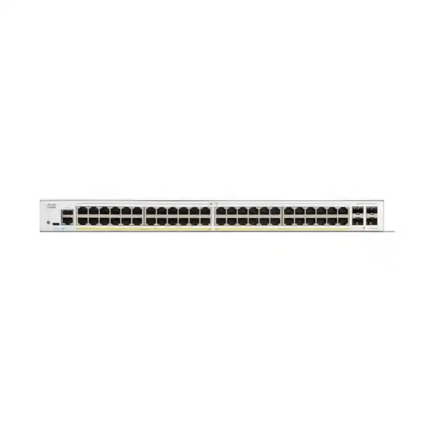
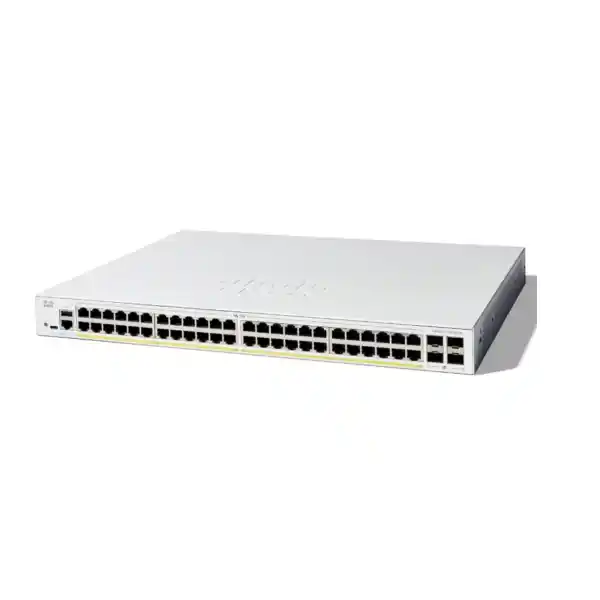
Cisco Catalyst C1300-48P-4G Network Switch
A 48-port managed Gigabit PoE+ access switch with four dedicated Gigabit SFP uplinks, 104 Gbps switching capacity, advanced Layer 2 and Layer 3 services, policy-based routing, enterprise access controls, IPv6 protection, resilient network features, and the operational simplicity required by growing UAE organizations.
Choose the C1300-48P-4G when you need forty-eight 1 Gigabit PoE+ access ports and 1 Gigabit fiber uplinks in a single rack unit, but do not require 10 Gigabit SFP+ uplinks, multigigabit copper access, PoE++, or hardware stacking on this particular -4G model.
What the Cisco Catalyst C1300-48P-4G is designed to do
The Cisco Catalyst C1300-48P-4G is best understood as a high-density managed access switch for business networks that still use Gigabit Ethernet at the user and device edge. It combines forty-eight copper Ethernet ports with PoE+ power delivery and four separate Gigabit SFP interfaces for fiber or copper transceiver uplinks. That port mix is valuable in offices, schools, clinics, retail locations, warehouses, hotels, training centers, and multi-department facilities where the access layer must connect many endpoints while keeping uplink cabling physically and logically separate from desk, camera, wireless, voice, or IoT ports.
The switch is not merely an unmanaged PoE distribution box. It supports detailed VLAN design, spanning-tree protections, link aggregation, multicast optimization, access control lists, 802.1X authentication, DHCP snooping, Dynamic ARP Inspection, IP Source Guard, IPv4 and IPv6 routing, RIP v2, policy-based routing, quality of service, SNMP, secure management, logging, discovery protocols, and network provisioning features. This gives an IT team substantially more control over segmentation, endpoint trust, traffic paths, voice prioritization, surveillance multicast behavior, and branch operational consistency than a basic Layer 2 switch.
For UAE deployments, the practical value is consolidation. A single switch can provide data and electrical power to many low-voltage network endpoints while supporting structured segmentation between corporate users, guest services, IP telephony, wireless infrastructure, CCTV, access control, printers, meeting-room devices, and management systems. This can reduce the number of local power adapters and simplify UPS-backed operation in the communications cabinet. The PoE budget must still be engineered carefully, because forty-eight PoE-capable ports do not mean that every port can draw the full 30W PoE+ maximum simultaneously.
The C1300-48P-4G is particularly suitable when 1 Gigabit uplinks are acceptable. Its four uplinks are Gigabit SFP, not 10 Gigabit SFP+. Organizations expecting heavy Wi-Fi aggregation, high-volume IP video concentration, large east-west server flows, or rapid growth beyond a few gigabits of aggregate uplink demand should consider a 10G-uplink model instead. Correctly positioned, however, the C1300-48P-4G offers a strong balance of port density, PoE capability, management depth, and acquisition efficiency for mainstream business access networks.
Core hardware and performance specifications
| Model | Cisco Catalyst C1300-48P-4G |
| Access interfaces | 48 × 10/100/1000BASE-T RJ-45 with PoE/PoE+ |
| Uplink interfaces | 4 × 1 Gigabit SFP |
| Total system Ethernet ports | 52 Gigabit Ethernet ports |
| Switching capacity | 104 Gbps, wire-speed and nonblocking |
| Forwarding performance | 77.38 Mpps at 64-byte packet size |
| PoE standards | IEEE 802.3af PoE and IEEE 802.3at PoE+ |
| Maximum PoE per port | Up to 30W class on supported PoE+ ports, subject to total switch budget |
| PoE budget reference | Cisco currently identifies 375W dedicated PoE in the detailed PoE table and describes the orderable model as a 370W power-budget configuration; conservative designs should size powered endpoints to the lower published figure |
| Packet buffer | 1.5 MB |
| MAC address table | 16,000 addresses for Catalyst 1300 1 Gigabit Ethernet SKUs |
| Jumbo frame support | Up to 9000-byte frame size |
| IPv4 routing scale | Up to 990 combined dynamic and static IPv4 routes and up to 128 IP interfaces on C1300 Gigabit Ethernet SKUs |
| Dimensions | Approximately 444.3 × 350 × 43.94 mm |
| Unit weight | Approximately 5.43 kg |
| Input power | 100–240V AC, 50–60 Hz, internal universal power supply |
| Operating temperature | -5°C to 50°C at sea-level conditions, with environmental limits applying at altitude |
Specification values should be validated against the exact regional bill of materials, firmware release, optics selection, and current Cisco documentation at quotation and deployment time.
Port architecture: 48 Gigabit PoE+ access ports plus 4 SFP uplinks
The front-panel architecture is straightforward for an access switch: forty-eight copper ports serve endpoint devices and four dedicated SFP slots provide Gigabit uplink connectivity. Because the SFP interfaces are separate rather than shared combo ports, an administrator can use all forty-eight RJ-45 access interfaces while maintaining fiber uplinks at the same time. This matters in dense wiring closets where every horizontal copper port may eventually be occupied and sacrificing an access port for uplink connectivity would create avoidable capacity pressure.
Each copper access interface can negotiate 10, 100, or 1000 Mbps according to connected device capability. In modern deployments, Gigabit negotiation is the normal target for PCs, printers, IP phones with pass-through PC ports, wireless access points, cameras, access controllers, and other Ethernet endpoints. The ability to tolerate slower legacy devices remains useful for specialized equipment that has not yet moved beyond Fast Ethernet. This can be particularly relevant in industrial offices, schools, warehouses, clinics, and properties where building systems may have long replacement cycles.
The four SFP uplinks accept appropriate Gigabit optical or copper transceivers supported for the platform and intended medium. Fiber uplinks help electrically isolate access cabinets, extend reach beyond twisted-pair Ethernet distances, and connect floors or buildings through structured fiber backbones. The exact transceiver, fiber type, connector presentation, wavelength, distance, and patching design should be selected as a system rather than treating the switch slot alone as the complete uplink solution.
The most important limitation to understand is uplink speed. The suffix “4G” indicates four Gigabit SFP uplinks. These are not 10G SFP+ uplinks. If the access layer is expected to aggregate multiple high-throughput Wi-Fi access points, large surveillance clusters, workstation backup traffic, virtualization hosts, or server traffic, Gigabit uplinks can become the controlling bottleneck even though the internal switching fabric is nonblocking. In those scenarios, a -4X model with 10 Gigabit SFP+ uplinks may be a better architectural fit.
PoE engineering: use the power budget, not the port count, to size endpoints
All forty-eight copper interfaces are PoE-capable, but the switch has a finite shared PoE budget. Cisco’s current specifications identify 375W as power dedicated to PoE in the detailed feature table, while the model description presents the C1300-48P-4G as a 370W power-budget configuration. For practical design in procurement documents, using 370W as the conservative planning ceiling avoids depending on the more generous table figure. The objective is not to consume every watt; the objective is to leave operational headroom for device startup behavior, endpoint replacement, camera heater or IR mode changes, access-point radio loading, and future additions.
A PoE+ port can support up to a 30W power class, but forty-eight devices drawing 30W each would require far more than the available shared budget. This switch is therefore best for mixed endpoint populations. A typical office might have twenty-four IP phones averaging 5–8W, ten cameras averaging 8–12W, six wireless access points averaging 15–22W, and several low-power controllers. The aggregate can fit comfortably when the actual device draw is calculated rather than assuming the maximum class on every port.
For surveillance deployments, camera specifications should be checked in worst-case conditions. Infrared illumination, heaters, pan-tilt-zoom motors, analytics processing, and accessory modules can increase power. A camera that normally draws 8W may reserve or demand more under peak conditions. Similarly, an enterprise wireless access point may support multiple radios and features that change its PoE requirement. Network design should therefore record both the negotiated PoE class and the manufacturer’s expected maximum draw for each endpoint type.
Persistent PoE support is useful when rebooting the switch because powered devices can continue receiving PoE during the reboot sequence where the platform and endpoint behavior supports it. Time-based PoE can also be used for selected endpoints where scheduled power control is operationally appropriate. These features can reduce unnecessary device power consumption or simplify controlled maintenance, but they should not be used blindly for security, life-safety, telephony, or building systems that must remain continuously available.
Voice-heavy office
Many IP phones usually draw modest power, so a 48-port PoE+ switch can support a high user count while preserving budget for selected access points and cameras. Verify pass-through requirements and phone models.
Camera-heavy site
Calculate worst-case camera draw, especially for PTZ, heaters, infrared emitters, and analytics. High-power camera fleets can consume the budget faster than their port count suggests.
Wireless-heavy floor
Confirm both PoE requirement and Ethernet speed. Modern multigigabit APs may be better served by a Catalyst 1300 multigigabit model rather than a 1G-access C1300-48P-4G.
Layer 2 switching features for segmented business networks
The C1300 platform supports a broad set of Layer 2 controls that allow a network to remain organized as device count and departmental complexity grow. VLAN capability includes port-based and 802.1Q tag-based VLANs as well as MAC-based, protocol-based, and IP subnet-based approaches. Private VLAN functions, protected-port behavior, guest VLANs, unauthenticated VLANs, dynamic VLAN assignment through RADIUS, voice VLAN support, multicast VLAN registration, VLAN translation, and Q-in-Q capabilities allow the switch to serve more than a basic single-subnet office.
A practical UAE office design might create separate VLANs for corporate workstations, voice, managed wireless access points, employee wireless users, guest Wi-Fi, CCTV, access control, printers, meeting-room systems, building management, and switch administration. Segmentation reduces the broadcast domain size and creates enforcement points for security policies at the switch, firewall, or routed gateway. It also simplifies troubleshooting because devices with similar trust levels and operational purpose can be grouped logically even when they are connected across different physical ports.
Spanning Tree Protocol functions protect against accidental Layer 2 loops that can otherwise create broadcast storms and destabilize an entire site. Rapid STP and Multiple STP allow faster convergence and more deliberate topology design, while BPDU Guard, Root Guard, loopback guard, and independent loopback detection provide additional defenses against miswiring or unauthorized switching devices. These safeguards are especially valuable in environments where users may connect unmanaged switches, conference-room devices, or temporary equipment without understanding Layer 2 topology consequences.
Link aggregation allows multiple physical links to operate as a logical group when both ends are configured compatibly. In the context of a 1G-uplink switch, link aggregation can provide additional aggregate capacity or resiliency to an upstream device, but the design must account for hashing behavior: a single traffic flow typically remains bound to one member link and therefore does not become a multi-gigabit single-flow connection simply because several 1G links are bundled. Aggregation is still highly useful for distributing many concurrent flows and protecting against a single-link failure.
Multicast controls such as IGMP snooping, IGMP querier, and proxy behavior help prevent multicast streams from flooding every access port. This is valuable for IP video distribution, certain surveillance architectures, digital signage, and specialized media systems. The Catalyst 1300 Gigabit Ethernet family supports substantial multicast group scale, but the operational design should still define where multicast routing or querier responsibilities reside and verify application behavior before deployment.
Layer 3 capability: more than simple static inter-VLAN forwarding
The Catalyst C1300 family can perform IPv4 and IPv6 routing in hardware, allowing the switch to act as a Layer 3 boundary for selected VLANs rather than forwarding every inter-VLAN packet to an external router. On the Gigabit Ethernet C1300 models, Cisco specifies support for up to 990 combined dynamic and static IPv4 routes and up to 128 IP interfaces. Interfaces can be configured on physical ports, link aggregation groups, VLAN interfaces, or loopback interfaces, giving network architects useful flexibility for campus-style access and distribution functions at modest scale.
RIP v2 is available for dynamic IPv4 routing, while policy-based routing allows traffic to be redirected toward a selected next hop based on IPv4 or IPv6 access control lists. PBR can be useful in controlled designs where different user groups, applications, or source networks must follow different paths. Examples include steering guest traffic toward a dedicated firewall interface, directing selected subnets toward a security appliance, or separating operational technology traffic from general corporate paths. PBR should be documented carefully because policy-driven forwarding can be less intuitive to troubleshoot than normal destination-based routing.
The switch can also operate as an IPv4 DHCP server for multiple pools and can relay DHCP across Layer 3 boundaries. UDP relay support can assist applications that depend on broadcast discovery across routed domains. These capabilities are helpful in branches where the switching layer is expected to provide local infrastructure services, but organizations with centralized DHCP, IP address management, and security policy normally keep authoritative services elsewhere and use relay functionality on the access or distribution layer.
One important distinction is OSPF. Cisco specifies OSPF v2 and v3 for C1300X SKUs, not for the standard C1300 Gigabit Ethernet model discussed here. Buyers should not assume that every Catalyst 1300 family member has identical routing protocols. If OSPF is a hard requirement, confirm an appropriate C1300X or other Cisco platform during design rather than selecting the C1300-48P-4G solely on port count.
For many small and midsize sites, the strongest use of Layer 3 features is selective: route local user and infrastructure VLANs at the switch where appropriate, keep security-sensitive north-south traffic controlled by the firewall, apply access lists between trust zones, and use a default route toward the security gateway. This can reduce unnecessary router-on-a-stick traffic while preserving centralized security inspection where it matters. The exact topology depends on compliance requirements, traffic patterns, redundancy strategy, and the capabilities of the upstream firewall or router.
Access-layer security for users, devices, and infrastructure
A managed access switch sits at one of the most important trust boundaries in the network because it is where laptops, phones, cameras, printers, wireless access points, controllers, and unknown devices physically enter the LAN. The C1300 platform includes multiple controls intended to reduce the risk created by unauthorized endpoints, spoofed addressing, rogue DHCP services, accidental loops, or unmanaged edge expansion.
IEEE 802.1X authentication allows a port to require identity validation through RADIUS before granting normal network access. Dynamic VLAN assignment can place authenticated users or devices into the appropriate VLAN based on policy, while guest and unauthenticated VLAN options can handle endpoints that cannot complete standard 802.1X workflows. MAC-based methods and web authentication provide additional admission options for device categories that lack full supplicant capability. A secure implementation should define fallback behavior carefully; simply allowing every failed authentication into a broad guest network can create new exposure.
DHCP snooping establishes a trusted view of legitimate IP address allocation and can block DHCP responses from unexpected interfaces, reducing the chance that a rogue device becomes an unauthorized DHCP server. IP Source Guard can use learned or configured bindings to prevent a port from sending packets with spoofed source addresses. Dynamic ARP Inspection can validate ARP information against trusted bindings, helping reduce man-in-the-middle risk on local broadcast domains. These three controls are most effective when designed together, with uplink and server ports explicitly marked as trusted only where necessary.
Access control lists can match many Layer 2, IPv4, and IPv6 attributes and can be applied at ingress or egress. Cisco specifies up to 1024 ACL rules for Catalyst 1300 1 Gigabit Ethernet SKUs. This gives administrators meaningful local enforcement capability, but ACL design should remain readable. Group policies by business intent, use consistent naming, document source and destination objects, and avoid filling the switch with one-off exceptions that are difficult to audit six months later.
IPv6 first-hop security is increasingly important because an organization can have IPv6 traffic even when administrators believe the network is “IPv4 only.” Router Advertisement Guard, Neighbor Discovery inspection, DHCPv6 Guard, and neighbor binding integrity functions help reduce rogue or spoofed IPv6 infrastructure activity. Properly deployed, these controls prevent an attacker or misconfigured device from becoming an unintended IPv6 router or manipulating local neighbor discovery behavior.
Secure management also matters. SSH and HTTPS are available for encrypted administration, SNMPv3 supports authenticated and encrypted monitoring workflows, and role-based operational discipline should be applied around administrator accounts, AAA, configuration backup, firmware management, and log collection. Where possible, place the switch management interface in a dedicated management VLAN, restrict it with ACLs, and allow administration only from authorized jump hosts, management networks, or VPN-connected engineering workstations.
Voice, wireless, video, and QoS considerations
The C1300-48P-4G can support converged networks where real-time communications, user traffic, surveillance, wireless infrastructure, and management traffic share the same physical switching platform. Quality of service becomes important in these environments because latency-sensitive voice should not compete equally with large backups or uncontrolled bulk transfers during congestion. The platform supports traffic classification and prioritization mechanisms that can be used to preserve service quality when links approach capacity.
Voice VLAN functions can automatically place compatible IP phones into a dedicated voice segment and apply appropriate QoS treatment. LLDP-MED and Cisco Discovery Protocol can assist endpoint discovery and configuration. In an IP telephony deployment, the design should also define DHCP options, call-manager reachability, VLAN tagging behavior through phone PC ports, emergency calling requirements, and whether the voice network must remain powered during a building power interruption through UPS-backed switching.
For wireless networks, the switch is well suited to standard 1 Gigabit PoE+ access points whose maximum Ethernet requirement fits within one Gigabit and whose power requirement fits within PoE+. However, modern high-performance access points may offer 2.5G, 5G, or faster Ethernet and may need higher PoE classes. Connecting such an AP to a 1G PoE+ port can create a performance or power ceiling. Network refresh projects should therefore compare the switch to the actual wireless generation being deployed rather than selecting a switch only from existing cabling counts.
For surveillance, Gigabit access is normally more than sufficient for individual cameras, but aggregation can become substantial with many high-resolution streams. A 48-camera switch can carry a large combined bitrate to network video recorders or analytics servers. If those servers are upstream across a single 1G link, that uplink may be the bottleneck. Link aggregation can spread multiple camera-to-server flows across several Gigabit links when the upstream architecture supports it, while a 10G-uplink switch may be simpler for heavy recording environments.
For AV-over-IP, digital signage, or multicast applications, IGMP snooping and querier behavior should be configured deliberately. Leaving multicast behavior to defaults can result in unnecessary flooding, while over-restrictive filtering can cause intermittent stream failure that is difficult to diagnose. Commissioning should include endpoint discovery, multicast group joins and leaves, failover, link utilization, and worst-case simultaneous content testing.
Management, provisioning, visibility, and operations
The value of a managed switch is realized over years of operation, not just on installation day. The Catalyst 1300 family provides a browser-based management interface with configuration wizards, system maintenance functions, monitoring tools, and searchable settings. It also supports command-line and protocol-based administration suitable for teams that prefer structured network engineering workflows.
SNMP versions 1, 2c, and 3 are supported, although SNMPv3 is preferred when authentication and privacy are required. Syslog, RMON, interface counters, event monitoring, and standard management information bases can integrate the switch into broader monitoring platforms. An operations team should alert on uplink errors, port flaps, PoE budget saturation, temperature, CPU or memory anomalies, authentication failures, spanning-tree changes, and unusual interface utilization rather than limiting monitoring to simple device reachability.
Cisco Network Plug and Play capabilities can simplify rollout by allowing preplanned configurations to be associated with devices before they reach the branch. This is useful for organizations deploying repeated branch templates across the Emirates or wider regional operations. Zero-touch concepts are most successful when the base configuration is standardized: management VLAN, AAA, NTP, DNS, syslog, SNMP, VLAN naming, uplink policy, edge templates, and security baseline should be consistent from site to site.
The series also supports discovery methods such as LLDP and Cisco Discovery Protocol. These protocols help identify neighboring devices, phone capabilities, interface relationships, and topology. In troubleshooting, accurate neighbor information can reduce the time needed to trace a cable from switch to switch or confirm where an access point, phone, or downstream infrastructure device is attached.
Operational discipline should include configuration backups before and after significant changes, firmware lifecycle management, clear naming standards, documented uplink diagrams, periodic review of unused ports, and a port description on every production interface. A 48-port switch can become difficult to maintain when interfaces are labeled only by number. Descriptions such as “AP-FLOOR2-EAST,” “CAM-LOADINGBAY-03,” “PHONE-FINANCE-12,” or “UPLINK-MDF-A” convert the switch configuration into a useful operational record.
UAE deployment patterns where the C1300-48P-4G fits well
Corporate office floor
Use separate VLANs for employees, IP phones, printers, meeting rooms, wireless AP management, guest Wi-Fi, and building systems. PoE+ powers phones and APs while SFP uplinks connect the access cabinet back to the main distribution frame. This is one of the most natural use cases when Gigabit uplink capacity is sufficient for the floor.
School or training center
Connect classroom APs, staff phones, smart displays, printers, cameras, and administrative PCs while isolating student, staff, guest, surveillance, and management traffic. 802.1X and dynamic VLAN assignment can improve identity-driven access where the authentication infrastructure is available.
Retail or hospitality location
Separate point-of-sale, staff, guest, voice, CCTV, digital signage, and property systems. The switch can power many edge devices from a UPS-backed rack, reducing distributed power adapters. PCI-related or guest isolation policies still require careful firewall and access-control architecture.
Warehouse and logistics office
Support cameras, barcode or operations terminals, phones, APs, printers, door controllers, and office users. Fiber uplinks are attractive where long distances or electrical separation make copper uplinks unsuitable. Verify environmental conditions inside cabinets and equipment rooms.
Clinic or professional practice
Create separate trust zones for staff devices, clinical or specialist equipment, voice, guest wireless, CCTV, printers, and management. Access policies should be aligned with the sensitivity of business and patient information, and critical communications should be protected by suitable UPS capacity.
Branch with local routing
Use switched virtual interfaces for local VLAN routing where appropriate, then send Internet and security-sensitive traffic toward the branch firewall. Policy-based routing and ACLs can refine flows, while DHCP relay centralizes address assignment if the organization uses shared services.
Fiber uplink planning in Dubai and wider UAE networks
The four SFP uplinks provide flexibility for connecting the access switch to another communications room, an upstream distribution switch, a core switch, or a firewall appliance through appropriate Gigabit transceivers. Fiber is frequently preferred for inter-floor and inter-building links because it supports longer distances and avoids conductive paths between electrically distinct areas. The correct design depends on whether the installed plant is multimode or single-mode fiber, the connector type presented at the patch panel, the required distance, and the supported optical module.
A common mistake is to order the switch first and optics later without checking the end-to-end link. Instead, document each uplink as a pair: local switch model and SFP, remote device model and SFP, fiber type, core count, connector presentation, patch-cord type, expected optical budget, and route distance. Both sides should use compatible optics. If an existing building backbone is OM3 or OM4 multimode, select suitable short-range Gigabit optics. If the link traverses a campus or long building path over single-mode fiber, choose optics appropriate to that plant and supported distance.
Because the switch has four Gigabit uplink slots, you can reserve links for different purposes. Two interfaces might form a link aggregation group to the primary upstream switch while another provides a separate service or management path. However, topology should be driven by failure domains rather than simply using every available interface. Two links in one cable tray can fail together if the tray is cut; two uplinks to the same upstream switch do not protect against upstream chassis failure. Resiliency must be evaluated end to end.
The bandwidth ceiling deserves explicit attention. A single 1G uplink provides around one gigabit per second of Ethernet line rate before protocol overhead. A group of high-volume endpoints can exceed that capacity even though each endpoint individually fits comfortably on a 1G access port. If capacity modeling predicts sustained or frequent multi-gigabit northbound traffic, select a 10G-uplink model rather than attempting to solve every bottleneck with link aggregation.
FourTeck can coordinate switch, optics, patching, rack integration, and upstream compatibility as part of a broader UAE network scope. For related infrastructure planning, visit FourTeck UAE for local technology solutions and FourTeck IT Services UAE for deployment and operational support services.
Important architecture limitation: this specific -4G model is not a hardware-stacking SKU
The Catalyst 1300 family includes models with hardware stacking, but the C1300-48P-4G is not listed among the stackable C1300 Family 1 models in Cisco’s current stacking specifications. The stackable 48-port PoE variants are associated with the -4X family that uses 10 Gigabit SFP+ uplinks. This distinction is easy to miss because product-family material discusses stacking at the series level. The specific model number must always be checked before a design assumes a physical stack.
If an organization requires multiple switches to behave as one hardware stack with active/standby control, cross-unit link aggregation, and simplified stack management, the C1300-48P-4G should not be specified as though it provides that function. Instead, evaluate an appropriate stack-capable -4X or C1300X model. For a standalone access switch, or for networks where multiple switches can be managed individually through a standardized configuration and monitoring platform, the lack of hardware stacking may be entirely acceptable.
This is also a reminder that closely related model names can hide meaningful differences. “48P” communicates 48-port PoE capability, but the uplink suffix changes the uplink speed and, in this family, also influences stacking eligibility. Procurement teams should quote the full orderable model rather than generic descriptions such as “Cisco 48-port PoE switch.”
VLAN segmentation blueprint for a 48-port PoE access switch
The following approach illustrates how the C1300-48P-4G can be structured in a real deployment. It is not a universal configuration template; VLAN IDs, IP addressing, ACLs, and routing policy must be adapted to the organization’s standards. The goal is to separate trust zones and operational roles so that an endpoint compromise does not automatically expose every other device on the switch.
| Example segment | Typical devices | Policy intent | Operational notes |
|---|---|---|---|
| Corporate users | PCs, laptops, docks | Access business services and Internet | Prefer identity-aware access where practical |
| Voice | IP phones | Reach call control, DNS, DHCP, NTP and required services | Apply QoS and LLDP-MED policy |
| Wireless infrastructure | AP management interfaces | Restrict management plane exposure | Check AP PoE and Ethernet speed requirements |
| Guest Wi-Fi | Visitor devices | Internet only or tightly restricted services | Prevent access to internal subnets |
| CCTV | IP cameras | Reach NVR, VMS, DNS/NTP as required | Block unnecessary Internet access |
| Access control / IoT | Door controllers, sensors | Limit to defined controllers and services | Use port security and ACLs where appropriate |
| Network management | Switches, infrastructure interfaces | Admins and monitoring systems only | Restrict with ACLs and secure protocols |
The switch supports up to 4094 VLAN identifiers with a portion reserved for internal usage. Real deployments rarely need anywhere near that number. The more important objective is a naming and addressing scheme that operators can understand quickly. VLAN names such as CORP-USERS, VOICE, CCTV, GUEST-WIFI, AP-MGMT, BMS, and NET-MGMT are more useful than unlabeled numeric segments. Apply the same names across branches whenever possible.
Performance sizing: how to decide whether 1G uplinks are enough
The 104 Gbps switching capacity indicates that the internal switching fabric is sized for wire-speed, nonblocking operation across the model’s Gigabit port complement under the vendor’s test assumptions. This does not mean every deployment will experience 104 Gbps of application throughput to external networks. Most traffic eventually traverses one or more uplinks, a router, firewall, WAN circuit, or server interface. End-to-end performance is determined by the narrowest resource in that path.
For a typical office, many endpoint ports are lightly utilized. A workstation may have a 1G link but average only a few megabits except during file transfers or updates. IP phones consume little bandwidth, and many cameras use single-digit or low double-digit megabit rates. Under these conditions, one or two 1G uplinks can be sufficient. The key is concurrency: forty-eight low-average devices can still produce large bursts if software deployment, backup, video export, or synchronized cloud activity occurs at the same time.
Surveillance is easier to model because camera bitrate can be estimated. Add the configured maximum bitrates of cameras whose streams cross the uplink, include overhead, consider secondary streams and viewing clients, and keep reserve capacity. Wireless is less deterministic because user demand changes throughout the day. If several APs each serve many active clients, the switch may see multi-gigabit aggregate traffic even though each AP has a 1G interface. In that case, link aggregation may help if many flows can be distributed, but moving to 10G uplinks gives simpler headroom.
The 77.38 Mpps forwarding rate also matters for packet-intensive traffic. Small packets create more forwarding work per unit of bandwidth than large packets. Cisco’s published forwarding rate for this model aligns with its wire-speed Gigabit architecture. Application experience still depends on queueing, QoS policy, congestion, endpoint performance, firewall inspection, and WAN quality.
A disciplined sizing exercise should document current average and peak uplink utilization, expected growth over three to five years, the number and type of access points, camera bitrate, cloud backup behavior, server locations, and whether local east-west traffic remains on the switch. If projected peaks regularly exceed roughly half to two-thirds of planned uplink aggregate capacity, the design team should evaluate faster uplinks rather than waiting for production congestion to become the trigger.
Physical, power, thermal, and rack planning
The C1300-48P-4G is a full-width rack-mountable switch measuring approximately 444.3 mm wide, 350 mm deep, and 43.94 mm high, with a unit weight of about 5.43 kg. A standard 19-inch rack or cabinet should provide adequate depth not only for the chassis but also for rear power cabling, front patch-cord bend radius, horizontal cable management, and airflow. Shallow wall cabinets that barely accommodate the chassis can become difficult to service once patch panels and PDUs are installed.
The internal universal power supply accepts 100–240V AC at 50–60 Hz. For UAE sites, the switch should be fed through a properly rated UPS where continuity is required for voice, wireless, CCTV, access control, or other powered devices. UPS sizing must include both the switch’s own consumption and the PoE load delivered to endpoints. A switch carrying hundreds of watts of PoE can require substantially more UPS capacity than a non-PoE data switch with the same number of ports.
Cisco publishes worst-case system power and power-with-PoE figures that are materially higher when the PoE budget is in use. Thermal design should therefore assume meaningful heat generation under load. The model uses one fan and Cisco identifies an acoustic level around 37.3 dBA at 25°C in current specifications. It is designed for equipment spaces, not silent desktop use. Rack ventilation, room cooling, dust control, and clear airflow paths should be part of deployment planning.
Cisco lists an operating range from -5°C to 50°C at sea-level conditions, with derating at altitude. This does not mean a communications closet should be allowed to operate near the upper limit continuously. In the UAE, summer ambient temperatures and unconditioned service spaces can be extreme. Network cabinets should be located in conditioned or appropriately ventilated areas, away from direct solar loading and high-dust zones. Temperature monitoring can provide early warning when building cooling fails.
Cable management is equally important. Forty-eight powered copper links plus four uplinks can create a dense front panel. Use labeled patch panels, appropriate patch-cord lengths, horizontal managers, and consistent port numbering. Keep fiber jumpers protected from sharp bends and accidental pulling. A clean rack improves airflow, speeds troubleshooting, and reduces the likelihood that a technician disconnects the wrong production link during maintenance.
C1300-48P-4G versus nearby Cisco Catalyst 1300 choices
The best switch is not automatically the model with the most ports. Select the variant that matches endpoint power, access speed, uplink speed, and growth expectations. The following comparison highlights the practical decision boundaries among commonly considered 48-port choices.
| Model | Access ports | PoE profile | Uplinks | Best fit |
|---|---|---|---|---|
| C1300-48T-4G | 48 × 1G copper | No PoE requirement | 4 × 1G SFP | Dense wired users where endpoints have separate power |
| C1300-48P-4G | 48 × 1G PoE+ | 370W-class published model description | 4 × 1G SFP | Mixed phones, APs, cameras and user devices with moderate total PoE draw |
| C1300-48FP-4G | 48 × 1G PoE+ | Much larger 740W-class budget | 4 × 1G SFP | High PoE density where 1G uplinks remain acceptable |
| C1300-48P-4X | 48 × 1G PoE+ | 375W-class published detailed budget | 4 × 10G SFP+ | Higher aggregate bandwidth and hardware-stacking requirements |
If wireless access points require 2.5G Ethernet, consider a multigigabit Catalyst 1300 variant instead of forcing them onto 1G ports. If endpoints require IEEE 802.3bt PoE++, evaluate an appropriate C1300X model. These decisions are easiest to make before purchase by building a complete endpoint schedule rather than by counting wall outlets.
When the C1300-48P-4G is the right choice
Choose it when
You need a dense 48-port managed access layer, most endpoints are 1 Gigabit or slower, PoE+ is enough for powered devices, the aggregate powered-device budget fits comfortably below roughly 370W, and 1 Gigabit SFP uplinks meet current and planned traffic demand.
Choose another model when
You require 10G SFP+ uplinks, hardware stacking, 2.5G or faster copper access, PoE++ for higher-power endpoints, a PoE budget approaching full 30W delivery across many ports, or a routing feature such as OSPF that Cisco reserves for C1300X SKUs.
This distinction protects project budgets. Overspecifying every access closet with the fastest available switch can waste capital, but underspecifying uplinks or PoE creates early replacement costs. The C1300-48P-4G occupies a useful middle ground for mainstream business Ethernet: high port density and strong management without the cost and power profile associated with multigigabit access or 10G uplink requirements.
Organizations that already standardize on Gigabit access and have measured uplink loads can often deploy this model confidently. Greenfield Wi-Fi-heavy campuses should model future radio generations more aggressively. A switch installed today may remain in service through multiple wireless refresh cycles, so the correct uplink and access-speed decision should reflect the expected life of the cabling and network rather than only today’s endpoints.
Designing the switch with a firewall and routed WAN edge
The C1300-48P-4G provides switching and routing features, but it is not a replacement for a next-generation firewall. Internet security, application inspection, threat prevention, VPN services, advanced web controls, and security logging normally remain functions of the firewall platform. A common branch architecture connects the Catalyst access switch to a firewall or to a distribution layer that in turn connects to the firewall.
In a simple design, the firewall can host the default gateways for user VLANs and the switch can carry 802.1Q trunks toward it. This centralizes inter-VLAN policy on the firewall but can force all east-west traffic through the security appliance. In a more distributed design, selected VLAN gateways can live on the Catalyst switch and the switch can route local trusted traffic directly while sending Internet and sensitive inter-zone traffic to the firewall. The right option depends on security policy, firewall throughput, audit requirements, and operational skills.
Policy-based routing can provide additional flexibility where selected sources must use a particular next hop, but it should not be used as a substitute for clear network architecture. Every PBR rule creates another forwarding decision that must be understood during troubleshooting. Maintain diagrams that show which VLAN gateway lives where, what the default route points to, which networks are locally routed, and which security zones are inspected by the firewall.
For firewall integration and segmentation projects in Dubai, see FourTeck Firewall Dubai. For organizations with operations extending beyond the UAE, FourTeck Africa provides a regional technology reference point for broader deployment planning.
Operational hardening checklist for production deployment
A switch can be technically capable and still be insecure if it is deployed with weak operational controls. Production configuration should begin with an approved baseline. Change default credentials, define named administrator accounts, use AAA where available, restrict management access, prefer SSH and HTTPS, configure SNMPv3 when supported by the monitoring platform, send logs to centralized storage, synchronize time, and establish backup procedures. Management traffic should be separated from ordinary user traffic where practical.
Unused access ports should be administratively disabled or placed into a non-routed quarantine VLAN according to local policy. Active edge ports should use explicit VLAN and security settings rather than relying on ambiguous defaults. Enable BPDU Guard on true edge ports where appropriate, but do not apply it indiscriminately to interfaces that legitimately receive spanning-tree protocol messages. Root Guard and loop protections should be placed according to the intended Layer 2 topology.
Deploy DHCP snooping by marking only legitimate server-facing or uplink paths as trusted. Build IP Source Guard and Dynamic ARP Inspection on a correct binding foundation. Misconfigured trust boundaries can block legitimate endpoints or provide false confidence. Pilot security controls on a small port group, verify phone and camera behavior, and then roll them out systematically.
For 802.1X, define what happens when RADIUS is unavailable, how phones with downstream PCs authenticate, how printers and cameras without modern supplicants are handled, and how contractors or temporary equipment are admitted. Many network access-control failures result from missing exception workflows rather than from limitations in the switch itself. Keep a secure but practical process for device onboarding.
Finally, document every physical connection. The switch should have a rack identifier, management IP, hostname, serial and asset records, uplink destinations, patch-panel mappings, optics list, UPS circuit, and configuration backup location. Accurate documentation changes a midnight outage from a cable-tracing exercise into a controlled repair task.
These controls also make future audits easier. Security teams can review port state, administrator access, VLAN exposure, DHCP trust, ACL policy, and firmware levels against a known baseline instead of reconstructing design intent from live configuration alone.
Firmware lifecycle, change management, and maintenance
Switch firmware should be treated as part of the security lifecycle. Before deployment, confirm that the selected release is appropriate for the organization’s stability requirements and review Cisco release notes for resolved issues, known limitations, upgrade paths, and configuration considerations. Production networks should not automatically chase every new release on publication day, but they also should not remain indefinitely on obsolete firmware.
Plan upgrades during approved maintenance windows and validate the configuration backup beforehand. Check the behavior of PoE endpoints during switch restart, particularly if critical phones, wireless access points, access controllers, or cameras depend on the device. Persistent PoE capability can reduce endpoint interruption in supported scenarios, but traffic forwarding still depends on the switch control and data planes returning to service.
Change management should record the reason for a change, expected impact, rollback approach, person responsible, and validation tests. For an access switch, seemingly simple changes can have wide impact. Changing a trunk’s allowed VLAN list can disconnect a floor. Modifying spanning-tree settings can alter paths across multiple switches. Replacing an SFP can introduce optic compatibility or fiber polarity issues. A brief implementation plan prevents many avoidable incidents.
Routine maintenance should include checking port error counters, CRC errors, packet drops, link flaps, PoE faults, high utilization, topology changes, temperature, fan state, and time synchronization. Intermittent copper errors often point to patching or cable problems rather than switch hardware. Optical errors should be investigated with connector cleaning, power-level checks, and correct optic selection before assuming a port failure.
Capacity reviews should happen before every major endpoint expansion. Adding ten cameras or replacing old APs with higher-performance models can change both PoE and uplink requirements. The switch may have free ports but insufficient power or uplink bandwidth. Keeping a live inventory of port assignment, PoE draw, and traffic utilization makes expansion decisions evidence-based.
UAE procurement and project specification guidance
A correct quotation should identify the full Cisco model, quantity, compatible power cord requirement, rack accessories, optics, patch cords, support requirement, deployment services, and any upstream hardware needed for the design. The switch model alone is not the whole bill of materials. If the four SFP uplinks will be used, each link requires an appropriate module at the local end and a compatible interface at the remote end. Fiber patch cords must match both the optic connector and installed fiber plant.
For PoE deployments, provide an endpoint schedule with device type, quantity, nominal wattage, worst-case wattage, PoE standard, and port speed. This makes it possible to determine whether the C1300-48P-4G’s budget is sufficient or whether a higher-power model is needed. A switch that is acceptable for forty-eight desk phones may not be acceptable for forty-eight high-power cameras even though the port count is identical.
For uplink design, provide the number of links, required speed, distance, fiber type, connector type, and upstream switch model. If the current network uses 10G at the distribution layer, buying a 1G-uplink access switch may create an avoidable mismatch. Conversely, if the site has a low-bandwidth WAN and modest local traffic, 1G uplinks may be entirely adequate and a 10G variant may not provide meaningful operational value.
For rack integration, confirm available U-space, cabinet depth, PDU outlet type, UPS capacity, cooling, patch-panel layout, and cable management. The C1300-48P-4G is approximately 350 mm deep, but connectors and cable bend radius increase practical clearance requirements. Power and PoE load also influence UPS runtime, so the battery design should use measured or conservative load estimates rather than the switch’s idle consumption.
For larger rollouts, standardize a configuration template and acceptance test. Each switch should arrive with the correct firmware, hostname, management address, VLAN set, uplink configuration, AAA policy, SNMP, logging, NTP, edge security template, and backup. Site acceptance should verify link speed, PoE delivery, VLAN reachability, routing, Internet access, voice registration, Wi-Fi operation, camera streams, and monitoring visibility.
Practical PoE sizing examples
PoE sizing becomes easier when treated as an arithmetic and risk-management exercise. The following examples are illustrative only; use actual vendor maximums for the devices being purchased.
Example 1: office with phones and APs. Suppose thirty IP phones are budgeted at 7W each, giving 210W, and six access points are budgeted at 18W each, giving another 108W. The combined design load is 318W. This sits below a conservative 370W planning limit, leaving about 52W of reserve. That reserve may be acceptable if the endpoint maximums are trustworthy and future growth is limited, but it should not be consumed casually.
Example 2: mixed office and CCTV. Suppose twenty phones are budgeted at 6W each, twelve cameras at 10W each, and four access points at 20W each. The total is 120W + 120W + 80W = 320W. Again, the design appears viable, but cameras with infrared, heaters, or PTZ mechanisms may require a higher worst-case allowance than 10W. Always size from the correct camera power specification rather than typical idle consumption.
Example 3: high-power wireless refresh. Suppose sixteen new access points require 25W each. The total would be 400W before adding any phones or cameras, so the C1300-48P-4G would not be a comfortable choice. A higher-PoE model or distribution of APs across multiple switches would be necessary. If those APs also provide 2.5G Ethernet, a multigigabit switch should be evaluated instead.
Example 4: all-camera edge. Thirty-two cameras at 11W each would total 352W. That leaves too little margin under a 370W conservative ceiling for comfortable design, especially if cameras can spike above the assumed draw. A higher-budget switch, fewer cameras per switch, or a split architecture would create better resilience and expansion space.
The key lesson is that available PoE port count and available PoE wattage are different resources. Track both independently. A design can run out of watts with ports still free, or run out of ports while significant wattage remains unused. Good switch selection balances both.
Frequently asked technical questions
Does the C1300-48P-4G provide PoE on all 48 copper ports?
Yes. The model is designed with 48 PoE-capable 10/100/1000 ports supporting IEEE 802.3af and 802.3at. The shared power budget still limits how much total power can be delivered at one time.
Are the four uplinks 10 Gigabit SFP+?
No. The C1300-48P-4G has four Gigabit SFP uplinks. The -4X family is the relevant direction when 10 Gigabit SFP+ uplinks are required.
Can this exact model be hardware stacked?
Cisco’s current stacking list does not include the C1300-48P-4G. Do not design it as a hardware-stacking switch. Evaluate a supported -4X or C1300X model if stacking is mandatory.
Does it support Layer 3 routing?
Yes. The C1300 Gigabit family supports IPv4 and IPv6 routing, Layer 3 interfaces, CIDR, RIP v2, policy-based routing, DHCP server and relay functions, and related routed features.
Does it support OSPF?
Not on this standard C1300 model according to Cisco’s current feature table. OSPF v2/v3 is specified for C1300X SKUs. Choose the platform against the routing protocol requirement.
Is the switch suitable for IP phones?
Yes. PoE+, voice VLAN features, LLDP-MED, discovery protocols, QoS, and VLAN segmentation make it well suited to IP telephony, assuming the overall PoE budget and call-control design are correct.
Is it suitable for IP cameras?
Yes for many camera deployments. Calculate worst-case camera wattage and aggregate video bitrate. A large camera fleet can stress the PoE budget or a 1G uplink even though individual access ports are sufficient.
Can it power modern Wi-Fi access points?
It can power APs that fit within PoE+ and a 1G Ethernet access link. APs needing multigigabit Ethernet or PoE++ should be matched to a different Catalyst 1300 or C1300X model.
What security features are most valuable at the access edge?
802.1X, ACLs, DHCP snooping, IP Source Guard, Dynamic ARP Inspection, BPDU protections, secure management, and IPv6 first-hop security are among the most useful controls when configured as a coordinated baseline.
How many VLANs can it support?
The platform supports VLAN identifiers up to 4094 with a portion reserved for internal use. Practical network design should prioritize a clean segmentation model rather than maximizing raw VLAN count.
Does it support jumbo frames?
Yes. Cisco specifies frame sizes up to 9000 bytes. End-to-end MTU consistency remains essential; one mismatched device can still cause fragmentation or connectivity issues.
Can FourTeck help with the full bill of materials?
Yes. A complete design can include the switch, optics, patching, rack integration, UPS considerations, firewall uplinks, endpoint PoE calculations, VLAN planning, configuration, testing, and documentation.
Why access switching design should be based on workloads, not only port quantity
Two sites can each require forty-eight physical ports and still need very different switch models. One may be a call center with low-power desk phones and ordinary PCs, while the other may be a smart building with high-power cameras, Wi-Fi 7 access points, digital signage, and large video flows. The first site could fit the C1300-48P-4G comfortably; the second might require multigigabit copper, a much larger PoE budget, PoE++, and 10G uplinks.
Start design by classifying endpoints into workload groups. Record Ethernet speed, PoE requirement, expected traffic direction, business criticality, VLAN, security posture, and redundancy requirement. Then calculate port quantity, wattage, uplink bandwidth, and failure impact. This process turns switch selection from a catalog exercise into an engineering decision.
Failure impact is especially important with a 48-port PoE switch. If one chassis powers forty phones, several APs, and a camera group, a switch outage affects many services at once. Splitting critical systems across multiple switches can increase resilience even when a single 48-port chassis has enough capacity. Conversely, consolidating devices onto one UPS-backed switch can simplify power protection and maintenance. The right tradeoff depends on service-level requirements.
Growth should be represented as more than spare ports. A design with ten free ports but only 15W of remaining PoE budget has little practical room for new cameras or APs. A design with plenty of PoE reserve but a consistently saturated uplink is also constrained. Reserve capacity should be tracked across physical ports, PoE watts, uplink bandwidth, and rack power.
This workload-based method also helps finance teams understand why a slightly different switch model may be recommended. The additional cost can be tied to a measurable requirement such as 10G uplink bandwidth, a larger PoE pool, multigigabit Wi-Fi support, or stacking—not simply to a vague preference for a more expensive model.
Implementation sequence for a clean migration
A structured migration reduces downtime when replacing an existing access switch. Begin by exporting the current port map and identifying each connected endpoint. Confirm which ports are access, trunk, voice-enabled, aggregated, or unused. Record VLANs, PoE status, link speed, descriptions, security policies, and uplink details. This inventory is the basis for the new configuration.
Build the C1300 configuration before the physical cutover where practical. Create the required VLANs, management interface, routing, ACLs, QoS, SNMP, NTP, syslog, authentication, and edge-port templates. Validate that the management network can reach the switch through the intended path. If fiber uplinks are used, test optics and patching before moving production endpoints.
During cutover, move uplinks and critical infrastructure first according to the approved plan, then migrate endpoint groups in a controlled order. Confirm link state, VLAN assignment, DHCP, DNS, gateway reachability, voice registration, AP adoption, camera recording, and PoE status after each group. Avoid moving all forty-eight ports blindly and troubleshooting a large collection of failures at once.
After migration, compare the live MAC table, PoE draw, uplink utilization, interface error counters, and monitoring visibility against the expected state. Update rack labels and as-built documentation. Keep the previous configuration and rollback plan until the new switch has passed the agreed stabilization period.
For new installations rather than migrations, the same sequence applies in a different order: validate rack and power, install the switch, establish management, update firmware if required, load the baseline, test uplinks, patch endpoints by functional group, verify security controls, and then conduct application acceptance testing.
Decision recap: who should buy the Cisco Catalyst C1300-48P-4G in UAE?
The C1300-48P-4G is a strong choice for organizations that need a professionally managed 48-port Gigabit PoE+ access layer and can confidently operate within 1G uplink and 370W-class PoE design limits. It is particularly attractive for offices, branch sites, education facilities, clinics, retail locations, hospitality environments, and mixed voice/CCTV/wireless deployments where most endpoints are 1 Gigabit or slower.
Its strengths are density, PoE convenience, 104 Gbps nonblocking switching, strong VLAN and multicast features, useful Layer 3 routing, policy-based routing, detailed ACL capability, 802.1X, DHCP snooping, Dynamic ARP Inspection, IP Source Guard, IPv6 first-hop security, secure management, and flexible Gigabit SFP connectivity. These features let the switch act as a controlled access platform rather than a simple connectivity device.
Its limitations are equally important. It does not provide 10G SFP+ uplinks, it is not listed as a hardware-stacking model, it does not provide multigigabit copper access, and it is not the correct choice for PoE++ endpoints. OSPF is associated with C1300X rather than this standard C1300 SKU. If any of those requirements are mandatory, select a different variant at the design stage.
Quotation input checklist
For an accurate Cisco Catalyst C1300-48P-4G quotation and deployment scope, provide the following information. Complete inputs reduce the chance of ordering the right switch with the wrong optics, insufficient PoE reserve, unsuitable uplink speed, or incomplete rack accessories.
Number of PCs, phones, cameras, access points, printers, controllers, meeting-room devices, and other Ethernet endpoints.
Maximum power draw and PoE standard for each powered endpoint, plus desired growth reserve.
Required number of uplinks, 1G suitability, fiber type, connector, distance, and upstream switch or firewall model.
Required VLANs, IP subnets, gateway locations, ACL boundaries, voice VLAN, guest access, CCTV, and management network.
802.1X, RADIUS, TACACS+, DHCP snooping, DAI, IP Source Guard, management ACLs, logging, and monitoring requirements.
Rack depth, available U-space, PDU outlet, UPS runtime target, cooling, cabinet location, and patch-panel layout.
Structured consultation for Cisco C1300-48P-4G deployment
A useful pre-sales consultation should validate the switch against the whole access-layer design. FourTeck can review endpoint port counts, PoE draw, uplink bandwidth, fiber optics, VLAN segmentation, firewall integration, rack power, UPS runtime, network management, migration sequencing, and acceptance testing before the final bill of materials is issued.
For UAE projects, the goal is to avoid both overbuying and under-sizing. If the C1300-48P-4G is the right fit, the scope can be optimized around it. If the project needs 10G uplinks, stacking, higher PoE, multigigabit access, or another routing capability, the recommendation can move to a better-matched Cisco variant before procurement.
Site location, endpoint list, PoE devices, uplink distance and fiber type, existing firewall/core model, rack details, expected growth, and required deployment date.
Cisco Catalyst C1300-48P-4G UAE — final selection summary
Select this switch when your project needs forty-eight managed Gigabit PoE+ access ports, four Gigabit SFP uplinks, mature VLAN and access-security controls, useful Layer 3 routing features, and a moderate shared PoE budget in a rack-mountable business platform. Confirm the full endpoint power schedule and uplink bandwidth before ordering, because these two resources—not the physical port count—are the most common reasons a 48-port PoE switch is undersized.
For a project-ready quotation, FourTeck can align the switch with optics, cabling, rack power, firewall connectivity, and deployment services so that the delivered configuration matches the actual site rather than a generic product list.

Reviews
There are no reviews yet.