
Managed Multi-Gigabit Access Switching for UAE Networks
Cisco Catalyst C1300-8MGP-2X Network Switch
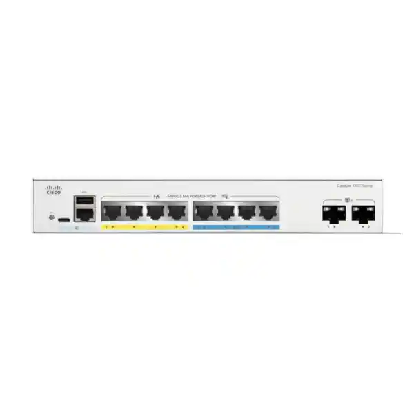
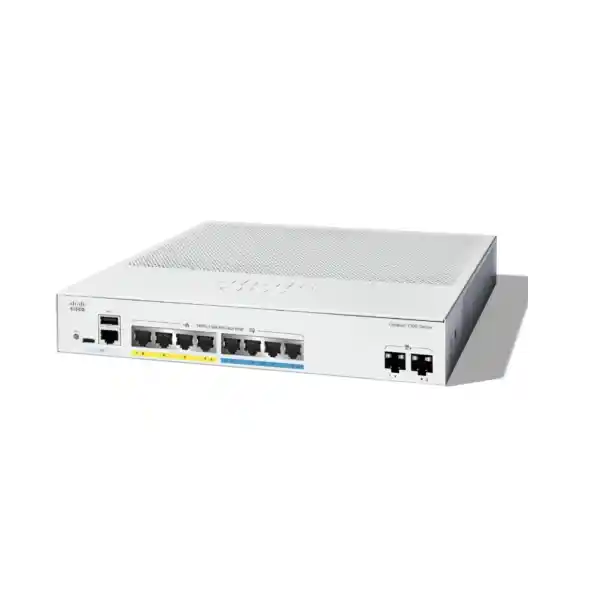
A compact fanless Catalyst 1300 platform combining four Gigabit PoE+ access ports, four 2.5G multi-gigabit PoE+ access ports, dual 10G SFP+ uplinks, a 120W PoE budget and advanced Layer 2/Layer 3 services for modern branch, wireless, voice, surveillance and edge-network deployments.
Direct answer: who should deploy the C1300-8MGP-2X?
The Cisco Catalyst C1300-8MGP-2X is a strong fit for UAE organisations that have outgrown simple Gigabit-only edge switching but do not need a large 24-port or 48-port access switch. Its distinctive value is the combination of eight powered copper access ports, half of which support 2.5 Gigabit Ethernet, with two dedicated 10 Gigabit SFP+ interfaces. That design suits compact locations where wireless access points, IP phones, cameras, collaboration endpoints and small servers must coexist without forcing every device onto the same one-gigabit bottleneck.
For a Wi-Fi-focused branch, the four 2.5G PoE+ ports can be assigned to multi-gigabit capable access points while the four standard Gigabit PoE+ ports serve phones, cameras or other edge devices. The two 10G SFP+ interfaces can then provide resilient or aggregated uplinks to a firewall, core switch, distribution switch, server room or another compatible Catalyst 1300 stack member. The result is a small switching platform that can support a surprisingly capable local topology without introducing fan noise into an office, reception area, clinic, classroom, retail store or meeting environment.
For procurement teams, the model is also attractive because it combines business-class switching, Layer 3 functions, stackability and PoE+ in a single chassis. It is not a replacement for an enterprise modular campus core, nor is it intended to deliver 60W/90W PoE to power-hungry endpoints. Its design target is different: efficient multi-gigabit access with manageable scale, strong segmentation and a clean path to 10G aggregation. FourTeck can position the switch as part of a broader UAE network design through FourTeck UAE, including switching, firewall, wireless, voice and infrastructure integration.
Cisco Catalyst C1300-8MGP-2X at a glance
Copper access
Eight PoE-capable RJ-45 access ports: four 10/100/1000 ports and four 2.5G multi-gigabit ports. Each access port supports up to 30W PoE+ within the switch’s total power budget.
High-speed uplinks
Two 10 Gigabit SFP+ interfaces provide high-bandwidth fiber or supported direct-attach connectivity for aggregation, server links, firewall interconnects or front-panel stacking.
PoE budget
A 120W switch-level PoE budget supports practical combinations of wireless access points, phones, cameras, badge readers and other IEEE 802.3af/802.3at powered endpoints.
Performance
Cisco specifies 68Gbps switching capacity and 50.60 million packets per second forwarding performance using 64-byte packets, with wire-speed nonblocking switching.
Silent hardware
The C1300-8MGP-2X is fanless, making it suitable for occupied rooms where acoustic noise from networking hardware can be disruptive.
Layer 3 services
IPv4 and IPv6 routing, Layer 3 interfaces, CIDR, RIP v2, policy-based routing, DHCP server/relay and UDP relay extend the switch beyond basic Layer 2 access.
Port architecture and traffic design
Port planning is where this model earns its place in a modern edge design. Four standard Gigabit Ethernet PoE+ ports are appropriate for devices whose throughput requirements remain comfortably below one gigabit per second. Typical examples include IP phones, 1080p or 4K surveillance cameras, printers, access-control controllers, thin clients and general office endpoints. These devices often benefit from PoE more than they benefit from multi-gigabit speed, so keeping them on the four 1G ports preserves the higher-speed interfaces for devices that can actually use them.
The four 2.5G multi-gigabit PoE+ ports address a different requirement. Newer wireless access points can aggregate more than one gigabit of traffic across multiple radio bands, particularly when client density is high or when Wi-Fi 6/6E deployments use wide channels and many concurrent clients. A 1G wired uplink can become a ceiling even when the radio layer is capable of more. A 2.5G Ethernet handoff provides more headroom while remaining compatible with conventional twisted-pair access cabling under appropriate cabling conditions. The switch therefore lets an organisation modernise the wireless edge without moving every copper endpoint to 10GBASE-T.
The dual 10G SFP+ uplinks are equally important because edge capacity is only useful if traffic can leave the switch efficiently. A single 10G uplink can carry aggregate traffic toward a distribution layer, firewall or server environment. The second interface can be used for a redundant path, link aggregation where supported by the adjoining device, a separate server/storage link, or front-panel stacking with compatible Catalyst 1300 family members. Physical media should be selected according to distance, fiber type and the supported Cisco transceiver matrix. For short cabinet-to-cabinet links, supported DAC options may reduce cost and simplify installation. For longer campus or inter-building connections, appropriate multimode or single-mode optics are more suitable.
A practical branch design might allocate the four 2.5G ports to wireless access points, two Gigabit ports to IP phones, one Gigabit port to a camera and one Gigabit port to an access-control or IoT gateway. One 10G SFP+ port could uplink to a firewall or distribution switch while the second remains available for redundancy or expansion. Another design could dedicate both SFP+ ports to a two-link LAG toward the core, provided the peer device and topology are configured accordingly. The correct choice depends on availability requirements, traffic patterns and whether Layer 3 routing is performed locally on the C1300 or centrally on a firewall/core device.
The important sizing principle is to avoid treating port count as the only metric. Eight access ports may sound small, but this switch has considerably more aggregate bandwidth than an ordinary eight-port Gigabit switch. When installed as a targeted wireless or converged edge switch, its port mix can be more useful than a larger unit with only 1G access and 1G uplinks. The value comes from placing the right endpoints on the right interfaces and ensuring the uplink architecture is sized for peak aggregate demand rather than average utilisation alone.
Performance: 68Gbps switching and 50.60Mpps forwarding
Cisco lists the C1300-8MGP-2X with 68Gbps of switching capacity and a forwarding rate of 50.60 million packets per second for 64-byte packets. The series is described as wire-speed and nonblocking. In practical terms, the switching fabric is engineered so that the port mix does not depend on a low-capacity shared backplane that would immediately constrain simultaneous traffic. This matters when several multi-gigabit access devices are sending toward one or both 10G uplinks at the same time.
Forwarding rate and switching capacity describe related but different characteristics. Switching capacity is an aggregate bandwidth figure for traffic entering and leaving the switching fabric. Packet forwarding rate expresses how many minimum-size packets can be processed each second. Real production traffic is a mix of frame sizes, protocols and burst patterns, so neither number should be treated as a direct prediction of application throughput. However, both figures are useful when comparing models and checking whether a switch has the architectural headroom expected for its physical interfaces.
The C1300 platform includes a 1.5MB dynamically shared packet buffer on this model. Buffering absorbs temporary bursts when traffic arrives faster than a destination port can immediately transmit it. The goal is not to turn a 1G destination into a 2.5G destination; persistent oversubscription will still cause queuing and potentially drops. Instead, buffering helps handle short-lived microbursts and speed transitions. Administrators should still design QoS and uplink capacity around real application priorities, especially for voice, video, storage and wireless aggregation.
The hardware platform also includes an ARM dual-core CPU at 1.5GHz, 1GB DDR4 memory for Catalyst 1300 models and 1GB SLC flash according to Cisco’s current platform specifications. Those control-plane resources support management, routing protocols, configuration processing and monitoring. Data-plane forwarding is handled by switching hardware rather than expecting the management CPU to forward ordinary production traffic. Cisco’s public datasheet does not identify a specific merchant-silicon or custom ASIC model for the C1300-8MGP-2X, so responsible design documentation should not invent one. What matters operationally is the published forwarding capacity, supported feature set and tested behavior of the platform.
For UAE deployments with low-latency applications, the design should also consider what sits upstream. A 10G uplink from the C1300 cannot compensate for a firewall limited to a much lower inspected throughput, a congested WAN circuit or a server whose network interface is saturated. Good switching design therefore starts with an end-to-end traffic path: endpoint speed, access switch, uplink, firewall or router, WAN or server interface, and return path. FourTeck can align this switch with security platforms available through Firewall Dubai so the access and security layers are sized together rather than independently.
PoE+ engineering and the 120W power budget
Per-port capability
All eight copper access ports support PoE functionality, with the model supporting IEEE 802.3af PoE and IEEE 802.3at PoE+. The product description identifies 30W PoE+ capability on the four 1G ports and four 2.5G ports.
Shared switch budget
The total PoE power allocation is 120W. That number is the critical constraint when several devices request power simultaneously. Eight ports at the maximum 30W each would exceed the available switch budget.
Operational controls
Catalyst 1300 supports time-based PoE scheduling and persistent PoE behavior, allowing administrators to manage power availability and keep powered endpoints supplied during switch reboot scenarios where supported by the platform behavior.
Sizing discipline
Use endpoint maximum or negotiated requirements, not only typical wattage. Reserve headroom for startup behavior, future device replacement and uncertain loads so an installation does not operate permanently at its power ceiling.
PoE design is frequently misunderstood because the number printed beside an individual port is not the same as the total switch budget. The C1300-8MGP-2X can provide up to 30W class PoE+ service per powered copper port, but its aggregate PoE budget is 120W. A network engineer therefore has to sum the realistic maximum requirements of all powered endpoints. Four 25W access points would consume up to 100W, leaving only 20W of budget for remaining devices. By contrast, four 15W access points and four 7W phones would total 88W, leaving a healthier margin.
The correct calculation depends on what the powered device actually negotiates and consumes. Camera heaters, infrared illuminators, wireless radio utilisation, USB accessories on desk phones and other endpoint features can change power draw. An access point that averages 13W may have a higher maximum specification. For tender and BOQ work, use the vendor’s maximum supported input requirement or a defensible design value rather than a quiet-period measurement from a lab. This avoids a situation in which the switch appears correctly sized during commissioning but reaches a power limit during a high-load event.
The 120W budget is especially suitable when the eight-port count is being used for a mixed endpoint set rather than eight high-power devices. A common design is to use 2.5G PoE+ ports for access points and Gigabit PoE+ ports for phones and cameras. If every port must power a device close to 30W simultaneously, a larger PoE budget model should be considered. The decision is not about whether the C1300-8MGP-2X can electrically negotiate PoE+ on each port; it is about whether the shared supply budget matches the sum of the planned loads.
UAE installations should also consider power quality, UPS runtime and thermal conditions. The switch uses an internal universal 100-240V, 50-60Hz power supply. When PoE endpoints are powered through the switch, a UPS protecting the switch can also keep those endpoints operating during a brief utility interruption, but the UPS must be sized for the switch plus PoE load rather than switch idle consumption alone. This is particularly relevant for security cameras, access-control systems, phones and wireless coverage expected to remain available during short outages.
Layer 2 switching, VLAN segmentation and loop control
A managed access switch is valuable not merely because it passes Ethernet frames, but because it lets administrators control where traffic is permitted to travel. The Catalyst 1300 platform supports standards-based VLAN segmentation, including 802.1Q tagging and a broad set of VLAN mechanisms. In a compact branch, separate VLANs can isolate corporate workstations, wireless guest traffic, IP phones, CCTV, access-control systems, IoT devices and management interfaces. This reduces unnecessary broadcast exposure and creates clean enforcement points for upstream firewalls or local Layer 3 policies.
Cisco documents support for up to 4094 VLAN IDs with a small high-numbered range reserved for internal use. The platform includes port-based and tag-based VLAN operation, MAC-based VLANs, protocol-based VLANs, IP-subnet-based VLANs, management VLAN functionality, private VLAN options, guest and unauthenticated VLAN behavior, and dynamic VLAN assignment through RADIUS with 802.1X. Not every deployment needs every mechanism. A disciplined design usually uses the simplest segmentation method that satisfies security and operational requirements, because unnecessary complexity increases troubleshooting time.
Voice VLAN functionality is useful when IP phones share physical access with user devices. The switch can classify and assign voice endpoints to a voice-specific VLAN and apply appropriate QoS treatment. LLDP-MED and Cisco discovery mechanisms also help identify connected network devices and exchange capabilities. In a mixed-vendor environment, engineers should validate exactly how endpoint discovery and VLAN assignment work with the chosen phone platform rather than assuming a Cisco-only workflow.
Spanning Tree remains important even in a small network because one accidental Layer 2 loop can generate broadcast storms and destabilise an entire site. Catalyst 1300 supports classic IEEE 802.1D STP, Rapid Spanning Tree using 802.1w, Multiple Spanning Tree using 802.1s and Cisco-oriented PVST+/Rapid PVST+ options. BPDU Guard and Root Guard add protection against unwanted topology changes at edge ports. A sensible branch configuration enables edge behavior only on true endpoint ports and protects those interfaces so a mistakenly connected small switch or loop cable does not become a network-wide event.
Link aggregation with IEEE 802.3ad LACP can combine compatible physical links into a logical channel for capacity and resilience. Cisco specifies up to eight groups and up to eight ports per group on the series. With only two SFP+ uplinks on this specific model, the most common use would be a two-link 10G LAG where the peer architecture supports it. Designers must remember that a LAG does not guarantee that one individual flow will use the full sum of all member links; traffic is distributed according to hashing behavior. The benefit is aggregate capacity across many flows plus redundancy if a member link fails.
Multicast handling is also available through IGMP snooping, querier and proxy functions. This matters in environments with IPTV, video distribution, multicast discovery or other one-to-many traffic. Without appropriate snooping, multicast can be flooded broadly across a VLAN like broadcast traffic. With correct multicast controls, the switch can limit delivery toward ports that have joined the group, reducing unnecessary load. Engineers should still consider where routing or multicast control resides elsewhere in the network, especially when the branch topology spans multiple VLANs or sites.
Layer 3 routing for branch and workgroup networks
The C1300-8MGP-2X is more than a Layer 2 access switch. Cisco’s Catalyst 1300 software supports wire-speed IPv4 routing, IPv6 routing, Layer 3 interfaces, Classless Inter-Domain Routing, RIP v2, policy-based routing, DHCP server functionality, DHCP relay and UDP relay. This allows the switch to perform inter-VLAN routing locally when that architecture is appropriate. For example, a management VLAN and internal server VLAN can be routed directly by the switch while guest traffic remains forced toward a firewall for policy enforcement.
Cisco specifies up to 990 combined dynamic and static IPv4 routes and up to 128 IP interfaces for the standard C1300 family. Those figures are ample for many small and medium branch designs, but raw route count should not be the only deciding factor. Engineers should decide whether the access switch or the firewall is the right Layer 3 boundary. Routing locally on the switch can reduce east-west traffic through the firewall and improve efficiency, while routing at the firewall provides a central place for security inspection and policy. The correct answer depends on data sensitivity, required controls and traffic volume.
RIP v2 is available for dynamic routing, but OSPF is not a standard C1300 feature; Cisco reserves OSPF v2/v3 support for C1300X models. This distinction matters in tenders and upgrade projects. If the branch routing design requires OSPF adjacency and fast dynamic convergence as a mandatory feature, the network architect should evaluate a C1300X or another suitable Cisco platform rather than assuming that every Catalyst 1300 model supports the same routing protocols.
Policy-Based Routing adds another level of control by letting forwarding decisions depend on ACL matches rather than only the normal destination route. In a small site, this can support specialised paths, but PBR should be used deliberately. It can make troubleshooting less intuitive if traffic takes a path that differs from the routing table. Every PBR deployment should therefore include clear documentation of match conditions, next hops, failover expectations and dependencies on upstream devices.
IPv6 capability helps organisations avoid designing an access layer that must later be replaced when dual-stack requirements expand. The platform supports IPv4/IPv6 coexistence, IPv6 host functions, neighbor discovery, stateless address autoconfiguration, DHCPv6 client operation, IPv6 routing, IPv6 QoS and IPv6 ACL functions. Even if an organisation is currently IPv4-dominant, enabling an IPv6-aware security posture is important because endpoints may generate IPv6 traffic by default. A network that ignores IPv6 can accidentally create a blind spot rather than eliminating the protocol.
Security controls at the access layer
Switch security begins at the edge because that is where users, phones, cameras, access points and unmanaged devices physically attach to the network. The Catalyst 1300 feature set includes IEEE 802.1X authentication with RADIUS integration, MAC authentication options, web-based authentication, port security, private VLAN mechanisms, protected ports, ACLs, storm control, DoS prevention, BPDU Guard, Root Guard, DHCP-related protections and secure management protocols. These controls do not replace a next-generation firewall, but they help reduce attack surface and enforce local trust boundaries.
802.1X is particularly useful in offices where physical port access should not automatically equal network access. The switch can operate as an authenticator, using RADIUS to validate endpoints or users before granting normal connectivity. Dynamic VLAN assignment can place an authenticated device into the correct segment based on identity or policy. Guest and unauthenticated VLAN options allow controlled fallback behavior. Deploying 802.1X properly requires coordination among switching, RADIUS, endpoint supplicants and certificate or credential management, so it should be implemented as a designed identity service rather than a single checkbox.
Port security can limit source MAC addresses and restrict how many addresses are learned on an interface. This can reduce casual misuse on fixed-device ports, such as a camera or printer connection. Private VLAN and protected-port functions can isolate devices at Layer 2 even when they share a larger logical segment. These mechanisms are useful for guest, IoT and surveillance designs where endpoints should reach an upstream gateway but should not directly communicate with each other.
Access Control Lists can match Layer 2 and Layer 3 fields, including MAC addresses, VLAN identifiers, IPv4/IPv6 addresses, protocols, TCP/UDP ports, DSCP or priority values and other packet characteristics. ACLs can be used for filtering or rate controls, but engineers should maintain a written policy model. A long collection of ad-hoc switch ACLs can become difficult to audit. Where security policy is complex, the switch should provide first-line segmentation while a firewall performs deeper inspection, logging, application control and threat prevention.
Management-plane security deserves equal attention. SSH and HTTPS should be preferred over insecure management methods. TACACS+ or RADIUS can centralise administrator authentication, while SNMPv3 can secure monitoring workflows. The switch supports configurable privilege levels, secure copy, dual firmware images and protected handling of sensitive configuration data. Management access should ideally be restricted to a dedicated management VLAN or trusted administration subnets, with configuration backups retained according to the organisation’s operational policy.
For UAE organisations implementing broader cybersecurity controls, switch hardening should be coordinated with firewall zoning, endpoint identity, wireless policy and logging. FourTeck’s IT Services UAE team can incorporate switching into a wider operational model that includes configuration standards, documentation, migration planning, monitoring and support rather than treating the switch as an isolated appliance.
Quality of Service for voice, video, wireless and business applications
When a small switch carries several application types, congestion management becomes important. The Catalyst 1300 family provides eight hardware queues, strict-priority and weighted round-robin scheduling, Layer 2 and Layer 3 classification, DSCP/CoS handling, ingress policing, egress shaping and rate-control options. These tools help ensure that delay-sensitive traffic is treated appropriately when a link becomes busy.
Voice is the classic QoS example because excessive delay, jitter or packet loss is immediately audible. A sensible design identifies voice traffic, preserves trusted markings only where appropriate, places it in a high-priority queue and prevents lower-priority bulk transfers from creating long queues ahead of it. However, priority traffic must still be controlled. If everything is marked as highest priority, QoS loses meaning. Administrators should define a small number of classes aligned with business requirements rather than assigning bespoke treatment to every application.
Wireless traffic adds another consideration. A single access point may carry corporate data, voice, guest internet access and IoT traffic. The wired switch sees this aggregate through one 2.5G port, often with multiple VLANs tagged across the connection. QoS markings and VLAN policies should therefore be consistent between the WLAN configuration and wired access layer. The 2.5G physical interface provides headroom, but QoS still matters when traffic converges onto a shared 10G uplink or a lower-speed internet circuit.
Surveillance traffic is typically steady rather than bursty, but many cameras combined can consume meaningful bandwidth. A camera VLAN can be rate-controlled or prioritised according to operational needs. Video management servers or NVRs may connect elsewhere in the network, so the traffic path should be mapped end to end. If several high-resolution cameras traverse a single uplink while other services share that path, capacity planning is more reliable than hoping QoS alone will solve chronic oversubscription.
iSCSI optimisation support is also documented within the Catalyst 1300 QoS feature set. This does not automatically make an eight-port edge switch the preferred storage fabric for every workload, but it provides useful traffic handling if iSCSI is present in a compact environment. Storage design should still consider loss sensitivity, multipathing, latency, MTU settings, server NIC configuration and whether dedicated switching is more appropriate for business-critical storage.
Front-panel stacking and growth strategy
The C1300-8MGP-2X supports hardware stacking as part of the Catalyst 1300 Family 1 group. Cisco documents stacks of up to eight switches, with the stack managed as a single system and supporting hardware failover. Front-panel stacking uses high-speed 10 Gigabit Ethernet interfaces, allowing organisations to grow beyond one chassis while retaining a unified management and control model.
Stacking can reduce operational complexity when multiple access switches are installed together. Instead of managing every unit as a completely separate island, a stack presents a more coherent system. Active/standby control, automatic numbering, ring or chain options and cross-stack functionality can simplify administration. Cisco also supports LAG across units in a stack, which can improve resiliency by allowing logical uplink designs that do not depend on one physical member alone.
There is an important family limitation: compatible PIDs from the same defined Catalyst 1300 family can stack together, but cross-stacking between different families is not supported. Procurement should therefore treat future stack compatibility as a design requirement. If a site starts with an C1300-8MGP-2X and expects to add larger members later, the planned models should be checked against Cisco’s current stacking-family matrix before purchase.
Stacking also consumes front-panel high-speed interfaces, so the uplink design must account for how SFP+ ports are allocated between stack interconnects and upstream network connectivity. On a model with only two SFP+ ports, this is particularly important. A ring stack and a redundant upstream topology can require more high-speed interfaces than a single small member offers. In some growth scenarios, it is operationally cleaner to deploy a larger model with more SFP+ ports rather than building an edge architecture that immediately exhausts the available interfaces.
The best growth strategy is therefore not simply “buy another switch when ports run out.” It is to forecast endpoint count, PoE demand, multi-gigabit demand, uplink count, redundancy and stack architecture together. The C1300-8MGP-2X is excellent as a compact high-value edge node, but larger Catalyst 1300 models can be a better fit where port density and high-availability uplink design dominate the requirement.
Management, visibility and troubleshooting
A switch becomes operationally valuable when administrators can understand what it is doing. Catalyst 1300 supports browser-based management, a scriptable command-line interface, SSH, SNMP, syslog, RMON, sFlow, port mirroring, VLAN mirroring, RSPAN, cable diagnostics, ping, traceroute and configuration transfer mechanisms. These capabilities are useful during deployment and become even more valuable when a problem must be isolated quickly.
sFlow can export sampled traffic information to an external collector, giving operations teams visibility into conversations and traffic patterns without requiring a full packet capture at all times. RMON provides local monitoring groups for statistics, history, alarms and events. Port mirroring allows selected interface traffic to be copied to an analyzer port for packet inspection, while RSPAN can extend mirroring across a Layer 2 domain. These tools help diagnose issues such as unexpected broadcast load, retransmissions, application latency, misbehaving endpoints or suspicious traffic.
Cisco’s dual-image firmware approach supports more resilient upgrade workflows. Administrators can maintain a known-good image while introducing a new release, reducing recovery complexity if an upgrade encounters problems. Configuration files are text-editable and can be transferred through secure mechanisms such as SCP. In multi-site environments, repeatable templates and documented change control are preferable to manually recreating every configuration from memory.
Smartports and Auto Smartports can simplify common access-port configuration by applying predefined or discovered roles. Automation is useful when it makes the intended configuration more consistent, but it should not hide the policy from administrators. Every automated port profile should be understood: VLAN assignment, spanning-tree behavior, QoS, security controls, PoE settings and allowed authentication methods should all match the endpoint category.
For troubleshooting physical problems, cable diagnostics and interface counters should be used before replacing equipment blindly. A multi-gigabit link may fall back to a lower speed because of cable quality, pair faults or termination problems. High error counters may point to a physical-layer issue rather than a switching fault. Good deployment practice includes certifying or validating copper links, documenting fiber types and transceivers, labeling patch panels and keeping uplink paths clear in network diagrams.
Physical design, thermals and UAE installation considerations
Fanless does not mean ventilation-free. The C1300-8MGP-2X still dissipates heat through its chassis and airflow paths, especially when PoE load is high. It should not be placed in a sealed cabinet with no thermal planning, stacked under heat-producing equipment without clearance, or installed where direct solar exposure drives enclosure temperature above room conditions. In the UAE, this matters in retail kiosks, guard rooms, warehouses, temporary offices and telecom cabinets where ambient temperatures can rise quickly if air conditioning fails.
Cisco lists an operating temperature range up to 50°C, but reliable infrastructure design should include margin. A comms cabinet that normally sits at 25°C but climbs to 48°C whenever a room AC unit fails is operating close to the top of the published envelope. Network designers should consider HVAC redundancy where business continuity is important, use temperature monitoring in remote cabinets and avoid locating switching hardware in unconditioned external spaces unless the installation is specifically engineered for that environment.
The internal universal 100-240V, 50-60Hz supply simplifies regional power compatibility, but the surrounding electrical design still matters. Use a properly rated PDU and UPS where downtime has operational impact. If the switch powers cameras, phones or access points, the UPS load calculation should include the PoE demand. A UPS sized only to the switch’s low-power idle state may deliver much shorter runtime once powered endpoints are drawing tens of watts.
Rack and cabinet planning should include patching space, fiber bend radius, optical module clearance and cable management. The compact 268mm width is useful, but rack-mount hardware should be installed according to the supplied mounting guidance. Copper cabling for 2.5G links should be validated for the actual channel. Where existing building cabling is old or poorly terminated, a multi-gigabit upgrade project should include physical-layer testing rather than assuming every run will negotiate 2.5G reliably.
10G SFP+ optics and uplink engineering
The two SFP+ ports allow the switch to connect into a wide variety of topologies, but transceiver selection must be intentional. Cisco’s published support list includes short-reach multimode 10G optics, long-reach single-mode optics, extended-reach variants, bidirectional options, copper twinax direct-attach cables and active optical cables. The correct module depends on distance, fiber plant, connector type, peer equipment and environmental requirements.
For a short link within the same rack, a supported direct-attach cable can be cost-effective and avoids the need for separate optical modules. For links between rooms or floors over multimode fiber, 10GBASE-SR is a common choice, with actual reach depending on fiber grade and channel conditions. For longer building or campus runs over single-mode fiber, 10GBASE-LR or other supported long-reach optics may be appropriate. The optical budget and fiber path should always be verified rather than choosing a transceiver based only on nominal distance.
Bidirectional optics can conserve fiber strands by transmitting in opposite wavelengths over a single strand, but they must be installed as matched complementary pairs. Extended-reach optics can support longer distances but may have additional optical-budget considerations. A design should document exact transceiver SKUs on both ends, fiber type, connector/patch-panel path and measured loss when required. This prevents commissioning delays caused by a physically compatible SFP+ form factor that is not actually suitable for the path.
When an SFP+ port is used for stacking rather than a normal uplink, its allocation should be reflected in the port plan. With only two high-speed interfaces, the design can quickly become constrained if the site expects both a resilient stack ring and redundant upstream connectivity. This is one reason network architecture should be finalised before purchasing optics. The switch itself is compact, but its SFP+ roles determine how gracefully the site can grow.
For direct server connectivity, a 10G link can be useful for a local application host, backup server, NAS or hypervisor, but the architecture should consider whether the server belongs on the access switch or on a dedicated aggregation/server switch. FourTeck’s Server Dubai infrastructure portfolio can be aligned with switching and uplink requirements so compute NIC speed, storage traffic, redundancy and network segmentation are sized as one system.
Use case 1: Wi-Fi 6 and Wi-Fi 6E access aggregation
Wireless access is one of the clearest reasons to select the C1300-8MGP-2X instead of a conventional eight-port Gigabit PoE switch. A modern access point can serve many clients across multiple radios. Even if a single client does not exceed one gigabit, aggregate traffic from dozens of clients can push beyond a 1G wired uplink. The switch’s four 2.5G PoE+ ports provide extra wired headroom without requiring 10GBASE-T to every access point.
A four-AP deployment should still be designed around radio capacity, WAN bandwidth and PoE requirement. If each access point requires no more than PoE+ and the combined power stays within the 120W budget, the C1300 can centralise connectivity cleanly. Corporate, voice, guest and IoT SSIDs can be mapped to separate VLANs and trunked through each AP port. The 10G uplink then carries aggregated wireless traffic toward a firewall, controller architecture or distribution layer.
The edge switch should not become the only security boundary for wireless clients. Guest networks normally require firewall enforcement and internet-only policy. Corporate WLANs may use 802.1X or other authentication mechanisms. IoT SSIDs may require strict east-west isolation. The Catalyst 1300 can provide the VLAN and QoS foundation while upstream security systems enforce application-level policy and internet controls.
The physical cabling path to each AP is equally important. A 2.5G-capable switch port does not guarantee a 2.5G link over a damaged or poorly terminated cable. During an upgrade, technicians should verify negotiated speed, error counters and cabling quality. This is especially important in hotels, older offices and retrofitted commercial spaces where horizontal cabling may have been installed over many phases.
Use case 2: converged voice, CCTV and office access
A compact branch often needs one switch to support several endpoint types. The C1300-8MGP-2X can place IP phones on a voice VLAN, cameras on a surveillance VLAN, workstations on a corporate VLAN and access points on tagged multi-VLAN trunks. PoE simplifies deployment because endpoints can be powered centrally from the wiring location instead of using local power adapters scattered around the site.
For voice, the design should use QoS and VLAN separation consistently. Phones usually consume modest bandwidth, so the 1G PoE+ ports are a natural fit. If a phone includes a downstream PC port, engineers should verify how voice and data VLANs are assigned and how authentication behaves for each logical endpoint. LLDP-MED or vendor-specific discovery can simplify provisioning, but the intended policy should remain explicit in the switch configuration.
Cameras are also well suited to the 1G PoE+ ports. Even high-resolution cameras commonly remain below Gigabit throughput, but the number of streams and video bit rate matter at aggregation points. Multiple cameras sending to a central NVR can create a sustained traffic flow through the uplink. The C1300’s 10G SFP+ connectivity provides ample local headroom for a small camera set, but upstream storage capacity and recording-server performance should be sized independently.
The four 2.5G ports can then remain available for wireless or other high-throughput edge devices. This mixed-port strategy is more efficient than consuming expensive multi-gigabit ports on endpoints that will never exceed 1G. It also creates a clear upgrade path: if a future device requires more throughput, the port plan can be adjusted without replacing the switch immediately.
Use case 3: branch office with local inter-VLAN routing
A branch with several internal VLANs can use the Catalyst 1300 as a local Layer 3 switch. For example, users, printers, voice devices and internal servers can reside on separate VLANs with switched virtual interfaces providing local gateway functionality. Traffic that is permitted between internal segments can be routed at wire speed by the switch, while internet-bound or security-sensitive traffic is sent to the branch firewall.
This architecture can reduce unnecessary load on the firewall, but it changes the security model. If two VLANs route locally at the switch, an upstream firewall does not see that traffic unless the design forces it through the firewall. ACLs on the switch can provide filtering, but they are not equivalent to a full security appliance with stateful inspection and application controls. Network architects should therefore decide explicitly which inter-VLAN flows are trusted enough to remain local.
RIP v2 can support dynamic routing in suitable environments, while static routes are often sufficient for a small branch. Policy-based routing can handle specialised paths when needed. Since OSPF is not supported on standard C1300 models, sites that require OSPF as an architectural standard should choose a different model family or maintain OSPF adjacency on an upstream router/firewall.
The 10G SFP+ interfaces provide flexibility for the upstream handoff. One link might connect to a central firewall pair or distribution switch while another provides redundancy. The final topology should consider whether the peer devices support LACP, first-hop redundancy, routed links or VLAN trunks. A network diagram should capture both physical cabling and logical VLAN/routing ownership so future support teams can understand the traffic path quickly.
Use case 4: retail, clinic, classroom and hospitality edge
The fanless design gives the C1300-8MGP-2X an advantage in locations where switching equipment cannot be hidden in a remote data room. Retail stores may place networking in a back-office cabinet near staff. Clinics may need quiet infrastructure close to consultation or reception spaces. Classrooms and training rooms can be sensitive to continuous fan noise. Boutique hospitality environments may have distributed communications cupboards close to occupied areas. In these cases, a silent switch improves the physical user experience while retaining enterprise-style management capabilities.
Compact sites also benefit from PoE because electrical outlets are not always available exactly where devices need to be mounted. Wireless APs can be installed on ceilings, cameras at entrances, IP phones on desks and access-control readers near doors while the power source remains central. This improves maintainability and allows selected endpoints to inherit UPS protection through the switch.
Segmentation is especially important in mixed-use environments. A retail branch may have POS terminals, staff devices, customer Wi-Fi, cameras and digital signage. A clinic may combine administrative systems, guest wireless, medical or IoT devices, phones and surveillance. A hotel may have guest-facing and back-office systems. The switch’s VLAN, ACL and authentication capabilities help create separated zones, while a firewall enforces internet and cross-zone security policy.
The main design caution is environmental. A silent fanless switch still requires a suitable temperature envelope and open ventilation. It should not be hidden in a sealed ceiling box, enclosed cabinet with no airflow or outdoor enclosure subject to UAE summer heat unless the whole installation is specifically engineered to maintain acceptable operating temperature.
Sizing methodology: choose the switch by constraints, not by headline port count
1. Count endpoints
List every connected device, including spare capacity for future APs, phones, cameras, printers, controllers and temporary equipment. Eight access ports should not be treated as eight permanently occupied ports if growth is expected.
2. Classify speed
Separate endpoints that truly require 2.5G from those that are well served by 1G. Reserve multi-gigabit ports for access points or other devices that can generate aggregate throughput above a gigabit.
3. Calculate PoE
Add the planned maximum power demand and maintain reasonable headroom within the 120W budget. Do not assume eight 30W devices can all run at maximum simultaneously.
4. Plan uplinks
Decide whether SFP+ ports are needed for core uplink, redundancy, server connectivity or stacking. Two 10G interfaces can be consumed quickly in a resilient design.
5. Define routing boundary
Choose which VLANs route locally and which must traverse a firewall. This determines SVI design, ACL requirements, default routing and how traffic is observed by security controls.
6. Forecast growth
Consider port density, stack membership, future wireless standards, higher-power PoE requirements and high-availability needs. If these exceed the model’s practical envelope, step up before installation.
This constraint-based method prevents a common procurement error: buying a switch because today’s port count fits, then discovering that tomorrow’s PoE load, uplink topology or multi-gigabit requirement does not. The C1300-8MGP-2X is best when its specific mix of 1G, 2.5G and 10G interfaces aligns with the network role. If most endpoints are simple 1G devices, a different Catalyst model may be more economical. If many devices need 2.5G or more than 120W PoE, a larger multi-gigabit model may be more appropriate. If OSPF or higher-power PoE++ is mandatory, the architecture should move toward the C1300X range or another suitably specified platform.
Migration from unmanaged or older Gigabit switches
Replacing an unmanaged switch with the C1300-8MGP-2X is not simply a physical swap. The managed platform creates an opportunity to improve VLAN design, security, monitoring and resilience. Before migration, document every existing connection, IP subnet, default gateway, DHCP scope, static endpoint and upstream trunk. Unmanaged networks often hide assumptions such as flat broadcast domains, daisy-chained switches and manually configured endpoints that can cause surprises during cutover.
When replacing an older managed Gigabit switch, export the current configuration and translate its intent rather than copying commands blindly. VLAN IDs, native VLANs, access/trunk modes, voice VLANs, LACP groups, STP priorities, ACLs, QoS policies and management IP settings should all be reviewed. Feature syntax and defaults may differ between product families. A migration is also a good time to remove unused VLANs, stale port descriptions and legacy insecure management protocols.
Multi-gigabit ports should be introduced deliberately. If an access point previously negotiated 1G, moving it to a 2.5G port may expose cabling problems that were not visible at Gigabit speed. Verify the negotiated link rate and check physical-layer counters after cutover. The same applies to SFP+ uplinks: confirm optic compatibility, fiber polarity and peer configuration before the migration window.
PoE endpoints should be inventoried by power requirement. If the old switch had a larger power budget, moving devices onto the C1300-8MGP-2X without recalculation can create avoidable power denial. Conversely, replacing local injectors with centrally managed PoE may simplify operations and improve UPS coverage. The design should account for all devices, including those that technicians may connect later as spares or replacements.
Finally, preserve a rollback path. Keep the old switch configuration, labeling and patching map until the new system has been validated. Test user data, voice calls, wireless access, camera recording, DHCP, DNS, internet access, management visibility and failover behavior. A successful migration is measured by service continuity and documented state, not merely by seeing green link LEDs.
Why the fanless design matters
Fanless switching has two operational advantages: acoustic silence and the elimination of a moving component that can wear over time. This does not mean the platform is maintenance-free, but it can be valuable in branch environments that do not have a dedicated equipment room. The C1300-8MGP-2X can sit in a properly ventilated cabinet near occupied space without adding continuous fan noise.
The trade-off is that thermal management depends on passive heat dissipation. Engineers must preserve clearance and ensure ambient conditions remain within specification. Dust buildup, poor cabinet ventilation and nearby heat sources can all reduce thermal margin. In UAE environments, air-conditioning assumptions should be documented, particularly for sites that shut down HVAC after business hours while networking remains powered continuously.
Energy-efficiency features also help reduce unnecessary consumption. Catalyst 1300 supports IEEE 802.3az Energy Efficient Ethernet on copper Gigabit interfaces, automatic power reduction when links are down, cable-length-based signal adjustment, manual LED disable options and time-based port or PoE operations. These capabilities will not transform network energy use by themselves, but they support a more disciplined operating model across many distributed sites.
For organisations with dozens of branches, small improvements can scale. A standard branch template that powers down unused PoE ports outside operating hours where appropriate, keeps firmware current, removes abandoned links and monitors temperature can reduce both energy waste and support incidents. The switch should therefore be viewed as part of an operational standard, not merely an appliance purchased once and forgotten.
Technical specification summary
| Specification | Cisco Catalyst C1300-8MGP-2X |
|---|---|
| 1G access ports | 4 × 10/100/1000 RJ-45, PoE+ up to 30W per port subject to total budget |
| Multi-gigabit access | 4 × 2.5G multi-gigabit RJ-45, PoE+ up to 30W per port subject to total budget |
| Uplinks | 2 × 10 Gigabit SFP+ |
| PoE standards | IEEE 802.3af PoE and IEEE 802.3at PoE+ |
| PoE budget | 120W total dedicated PoE power |
| Switching capacity | 68Gbps |
| Forwarding rate | 50.60Mpps for 64-byte packets |
| Packet buffer | 1.5MB aggregate dynamically shared buffer |
| Control-plane hardware | ARM dual-core 1.5GHz CPU, 1GB DDR4, 1GB SLC flash for Catalyst 1300 platform |
| Layer 3 | IPv4/IPv6 routing, Layer 3 interfaces, CIDR, RIP v2, PBR, DHCP server/relay, UDP relay |
| Stacking | Front-panel hardware stacking, up to 8 compatible switches within supported Catalyst 1300 family grouping |
| Console | Cisco standard RJ-45 console and USB Type-C console/file management interface |
| Dimensions | 268 × 298 × 43.94 mm |
| Weight | Approximately 2.64 kg |
| Cooling | Fanless |
| Input power | Internal universal 100-240V, 50-60Hz |
| Operating temperature | -5°C to 50°C |
Procurement guidance for Dubai and the wider UAE
Enterprise and SMB switch procurement should start with the exact model identity: C1300-8MGP-2X. Similar Catalyst 1300 names can represent significantly different port mixes, PoE budgets and uplink types. A quotation should state the switch PID clearly and list any SFP+ modules, DAC cables, rack accessories, patch cords, UPS equipment and installation services as separate line items where applicable. This avoids ambiguity between the base switch and the optics required to complete the network path.
Transceivers are particularly important in UAE projects because the “switch price” alone may not represent the installed uplink cost. A pair of 10G optics may be required for each fiber link, and the correct type depends on the existing fiber. If a site has multimode OM3/OM4 infrastructure, the solution differs from a building with OS2 single-mode fiber. An accurate quote should therefore include fiber type, distance and peer-device model whenever possible.
PoE endpoints should be included in the BOM sizing conversation. If the switch is being purchased to support four access points and four cameras, the exact endpoint models determine whether 120W is sufficient. A procurement team should not accept a statement such as “eight PoE ports means eight PoE devices” without a wattage calculation. The same applies to wireless speed: if the chosen APs have 2.5G Ethernet interfaces, a standard Gigabit switch would constrain their wired backhaul.
Warranty and support requirements should also be clarified for the project. Cisco’s current Catalyst 1300 documentation describes limited lifetime warranty coverage and support provisions for the series, but organisations may have specific service-level, replacement-time or support-contract requirements beyond base coverage. These should be quoted and documented explicitly rather than inferred from the hardware purchase.
For multi-site organisations in Dubai, Abu Dhabi, Sharjah and other Emirates, consistency is often more valuable than buying each branch independently. A standard edge-switch template can define approved firmware, management addressing, VLAN IDs, QoS, authentication, SNMP/syslog destinations, port profiles and backup procedures. This reduces operational variance and makes remote support easier. The C1300-8MGP-2X can serve as that compact template where its eight-port capacity and 120W budget align with branch requirements.
FourTeck can supply the switch as part of a complete network scope rather than as a standalone box. That scope may include switching, firewall integration, wireless deployment, structured-cabling checks, optics selection, VLAN design, migration, testing and documentation. The broader FourTeck global network and infrastructure portfolio is also relevant for organisations coordinating regional projects beyond the UAE.
When this model is the right choice — and when it is not
The C1300-8MGP-2X is a strong choice when a site needs a small number of access ports but demands more than ordinary Gigabit edge switching. It is especially effective when up to four key devices need 2.5G connectivity, all or most endpoints need PoE/PoE+, silent operation is desirable and one or two 10G uplinks are required. The combination is well aligned with modern small branches, Wi-Fi-focused edge closets, meeting environments and distributed enterprise sites.
Consider a larger Catalyst 1300 model when the site has more than eight powered endpoints, needs greater total PoE budget, requires more than four 2.5G access ports or needs four SFP+ uplinks for more flexible stacking and redundancy. A 24-port or 48-port multi-gigabit model can provide a better expansion path when the branch is expected to grow quickly.
Consider Catalyst 1300X or another platform if 60W PoE++ or OSPF is a mandatory requirement. Standard C1300 models such as the C1300-8MGP-2X support PoE+ and RIP v2 but do not provide the C1300X-specific OSPF capability. Requirements should be mapped to the exact product family rather than extrapolated from a series name.
Consider a different architecture if the switch is expected to act as a high-density server aggregation layer, large campus core or storage fabric. The C1300-8MGP-2X is optimised for compact managed access and branch use. Its strength is the balanced 1G/2.5G/10G port mix, not massive port density or modular core expansion.
Making this distinction before purchase reduces total project cost. The cheapest switch that meets only today’s port count can become expensive if it forces premature replacement. Conversely, buying a much larger platform than the site needs can waste budget and rack space. The best design matches current constraints, planned growth and operational standards with realistic margin.
Deployment checklist for network engineers
Before installation
Confirm firmware target, management IP plan, VLAN table, STP root design, uplink optics, rack location, power/UPS capacity, endpoint PoE requirements, copper cabling condition and peer-device configuration.
During installation
Label ports, record serial/model details, install optics correctly, verify negotiated speeds, set secure management access, configure NTP/SNTP, syslog and monitoring, then apply endpoint-specific port profiles.
Validation
Test DHCP, DNS, VLAN isolation, routing, internet access, voice quality, AP uplink rate, camera recording, PoE headroom, LACP or redundant path behavior, management access and monitoring visibility.
After handover
Export configuration backups, update diagrams, document optic types and fiber paths, record firmware, retain baseline interface statistics and establish a controlled process for configuration and software changes.
Frequently asked technical questions
Does every copper port support PoE+?
Yes. The product configuration provides PoE+ capability across the four 1G and four 2.5G access ports. The total available PoE budget is 120W, so aggregate endpoint demand must remain within that limit.
Can all eight ports deliver 30W at once?
No. Eight ports at 30W would require 240W. The switch has a 120W total PoE budget, so actual powered-device combinations must be sized according to negotiated or maximum endpoint requirements.
Is the switch fanless?
Yes. Cisco lists the C1300-8MGP-2X as fanless, which makes it well suited to quiet office and edge environments, provided ambient temperature and ventilation remain within specification.
Does it support Layer 3 routing?
Yes. The Catalyst 1300 platform supports IPv4 and IPv6 routing, Layer 3 interfaces, RIP v2, CIDR, policy-based routing, DHCP server and relay functions. OSPF is a C1300X-specific capability, not a standard C1300 feature.
Can it be stacked?
Yes. The C1300-8MGP-2X belongs to a Catalyst 1300 family group that supports front-panel hardware stacking of up to eight compatible switches. Cross-family stacking is not supported.
Are the uplinks 1G or 10G?
The model provides two 10G SFP+ interfaces. Exact transceiver compatibility and distance depend on the selected Cisco-supported optic or cable and the physical media.
Is 2.5G useful for Wi-Fi?
Yes. Multi-gigabit Ethernet can prevent the wired uplink from becoming a one-gigabit ceiling for capable access points serving many clients. Actual benefit depends on AP model, client load, radio configuration and upstream bandwidth.
Can the SFP+ ports be used for servers?
They can be used for supported 10G Ethernet connectivity, including server or storage-facing links where the architecture is appropriate. Network designers should still consider redundancy, peer compatibility and whether a dedicated server aggregation layer is preferable.
Decision recap: the role this switch fills best
The Cisco Catalyst C1300-8MGP-2X is best understood as a compact multi-gigabit managed access switch with serious uplink and network-control capability. It solves a specific edge problem: a small site may only need eight wired devices, but four of those devices may require more than Gigabit Ethernet, most may require PoE, and the site may need 10G uplink capacity to avoid creating a new bottleneck. Ordinary compact switches often satisfy only one or two of those needs.
Its four 1G PoE+ ports handle traditional endpoints efficiently. Four 2.5G PoE+ ports support bandwidth-hungry wireless or edge devices. Dual 10G SFP+ interfaces create a fast aggregation path. The 120W PoE budget is sufficient for many mixed deployments when designed properly, though it must be calculated rather than assumed. Layer 2 segmentation, Layer 3 routing, 802.1X, ACLs, QoS, monitoring and hardware stacking bring the operational features expected from a managed business switch.
The fanless chassis expands where the switch can be installed, while its 268 × 298 × 43.94 mm physical dimensions keep it compact. The main constraints are equally clear: only eight access ports, only four 2.5G ports, a 120W shared PoE budget, two SFP+ interfaces and no OSPF on the standard C1300 platform. Those are not flaws when the product is used in its intended role; they are design boundaries that should be checked before purchase.
For a UAE branch, retail site, clinic, hospitality edge, classroom, meeting facility or wireless aggregation point, the C1300-8MGP-2X can provide a clean balance of speed, power, silence and manageability. The strongest deployment is one where endpoint count, PoE draw, uplink architecture and security boundary have already been mapped to the switch’s exact capabilities.
Quotation input checklist
For an accurate UAE quotation and design, provide the following project inputs. Supplying these details reduces the risk of incorrect optics, insufficient PoE budget or a switch size that does not match the final topology.
FourTeck UAE Network Consultation
Plan the C1300-8MGP-2X as part of the complete network, not as an isolated line item
FourTeck can assist with switch sizing, PoE calculations, 2.5G access design, 10G optics, VLAN and Layer 3 architecture, firewall integration, wireless uplinks, migration, testing and documentation. A correct design starts with endpoint and traffic requirements and ends with a tested, supportable configuration.
Recommended consultation outputs
- Validated switch and optic bill of materials
- PoE budget and endpoint power worksheet
- VLAN, routing and firewall-zone map
- Uplink redundancy or stacking plan
- Migration and rollback procedure
- As-built documentation and configuration baseline

Reviews
There are no reviews yet.