
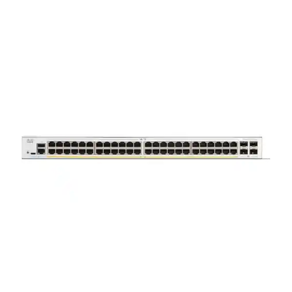
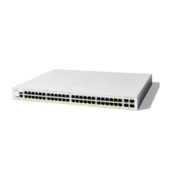
Cisco Catalyst C1300X-48P-4X Network Switch
A high-density 48-port Gigabit PoE managed switch engineered for business access networks that need a large power budget, four 10 Gigabit uplinks, hardware stacking, strong Layer 2 controls, dynamic Layer 3 routing, enterprise access security and operational simplicity without moving to a large campus chassis architecture.
Direct answer: who should choose the C1300X-48P-4X?
Choose the Cisco Catalyst C1300X-48P-4X when one wiring-closet access switch needs to connect many standard Gigabit Ethernet endpoints and also power a substantial number of devices such as Wi-Fi access points, IP phones, CCTV cameras, access-control terminals, intercoms, thin clients, digital signage controllers or IoT gateways. Its value is not simply that it offers forty-eight RJ45 ports. The practical advantage is the combination of a 740 W shared PoE budget, four high-speed fiber-capable uplink interfaces, stackability, advanced Layer 2 controls, wire-speed Layer 3 routing and enterprise access security in a single rack-mountable platform.
The model is especially suitable where the endpoint edge remains predominantly 1 Gigabit Ethernet but the distribution design requires multiple 10 Gigabit uplinks or resilient stack interconnects. If most new wireless endpoints require 2.5G or 5G multigigabit access, another C1300X model may be more appropriate. If the environment is still based on 1G endpoint access and needs maximum PoE density per rack unit, however, the C1300X-48P-4X is a strong fit. FourTeck can position it inside a wider UAE switching, security and infrastructure plan through FourTeck UAE, including optics, rack design, cabling, firewall connectivity and implementation services.
Verified hardware profile
- 48 × 10/100/1000 Ethernet access ports.
- PoE support across 48 access ports with 740 W total PoE power budget.
- 4 × SFP28 interfaces, operating at 10G for uplinks and supporting 25G for stacking.
- 176 Gbps switching capacity and 130.95 Mpps forwarding performance.
- 3 MB dynamically shared packet buffer.
- 2 GB DDR4 DRAM and 1 GB SLC flash.
- ARM dual-core CPU at 1.5 GHz.
- Rack-mountable 1U enclosure.
Operational capabilities
- Hardware stacking of up to eight compatible C1300X units.
- OSPFv2 and OSPFv3 on C1300X platforms, plus RIP v2, static routes and policy-based routing.
- Up to 7168 combined dynamic and static IPv4 routes and up to 256 IP interfaces for C1300X class platforms.
- 802.1X, RADIUS, TACACS+, DHCP snooping, Dynamic ARP Inspection and IP Source Guard.
- QoS with eight hardware queues, WRR and strict-priority scheduling.
- Web UI, CLI, SNMP, Cisco Business Dashboard and Cisco Network Plug and Play support.
- IPv4/IPv6 dual-stack management and forwarding features.
Port architecture and traffic flow
The front-panel architecture makes the C1300X-48P-4X straightforward to use as a dense access-layer switch. Forty-eight copper interfaces deliver traditional 10/100/1000 Mbps Ethernet for endpoint attachment. In a properly designed access network, these ports normally terminate user devices, phones, cameras, printers, access points, controllers and building systems, while the four SFP28 interfaces are reserved for northbound connectivity, inter-switch aggregation or stack functions. Cisco specifies the SFP28 interfaces for 10 Gigabit uplink operation, with 25 Gigabit capability available for stacking rather than ordinary 25G uplink service. That distinction matters when sizing the network: procurement teams should not treat this switch as a four-port 25G access-uplink platform.
At full duplex, the access edge can generate far more aggregate endpoint traffic than most branch or mid-market networks sustain continuously. The four 10G uplink interfaces therefore allow useful oversubscription choices. A simple design may use one 10G uplink and keep another for redundancy. A more resilient design can use two 10G links as an LACP bundle to a distribution pair, subject to the topology and stack design. Larger sites may dedicate interfaces to separate aggregation paths or use the SFP28 ports for hardware stacking. What matters is that the uplink plan should be based on measured traffic patterns rather than on port count alone. Forty-eight users connected at 1G do not normally transmit at line rate simultaneously, while camera, backup, storage or wireless traffic can create sustained flows that deserve specific uplink analysis.
The switch is nonblocking at its rated switching capacity, with Cisco listing 176 Gbps and 130.95 million packets per second for 64-byte traffic. These values are particularly relevant when the device is used for inter-VLAN routing or as part of a stacked access system. They show that the switching silicon is designed to forward at wire speed rather than behave like a low-end smart switch whose control and data planes become bottlenecks as policy features are enabled.
PoE engineering: understanding the 740 W budget
The 740 W PoE budget is one of the main reasons to select the C1300X-48P-4X. Power budget is a shared resource, so the correct design process starts by building an endpoint power schedule rather than simply counting ports. A 48-port switch may power forty-eight devices only if the combined negotiated draw remains within the platform budget and within the supported per-port power behavior. Cisco positions the C1300X-48P-4X as a 48-port PoE model with a 740 W total power allocation. In practical deployments, this creates substantial headroom for typical IP phones, fixed cameras and standard Wi-Fi access points, while still allowing higher-draw devices to coexist when the aggregate calculation is controlled.
For example, a hospitality floor might include twenty-four IP phones drawing moderate power, twelve ceiling access points, eight surveillance cameras and several access-control devices. A school might have classroom access points, interactive panels with network adapters, phones and cameras. A warehouse may have rugged wireless endpoints, cameras and time-attendance units. Each project should capture the maximum expected device draw, not only the typical average, because boot-up, heater activation on outdoor cameras, radio utilization or accessory modules can increase consumption. Add an engineering margin so that future moves, adds and changes do not force an immediate switch replacement.
Persistent PoE support is operationally useful because Cisco provides a mechanism to maintain PoE power while the switch itself reboots. This can reduce endpoint disruption during specific maintenance events, particularly for devices that take several minutes to restart. Persistent power does not eliminate the need for UPS protection; it complements it. For UAE installations, UPS runtime and cooling should be sized for the switch plus powered endpoints because the electrical load of a fully utilized PoE switch is materially higher than the switch silicon alone. The datasheet lists worst-case consumption with PoE close to the full platform load, so rack PDU, UPS and circuit sizing should consider maximum demand, not just idle consumption.
PoE design should also follow cabling quality. Heat buildup in large copper bundles, patch-panel density and conductor gauge affect efficiency and long-term reliability. Category 5e or better meets Gigabit Ethernet requirements, but new structured-cabling projects often standardize on higher category cabling for better margin and future migration. FourTeck’s UAE IT services team can align switch power budgets with rack, UPS, patching and endpoint schedules so that the Bill of Materials reflects real deployment conditions.
Performance sizing
With 176 Gbps switching capacity and 130.95 Mpps forwarding, the platform is sized for wire-speed switching across its port architecture. This is important when ACLs, VLAN segmentation, QoS and routing are part of the design. The 3 MB shared packet buffer helps absorb short bursts, but it should not be mistaken for deep-buffer data-center behavior. Proper QoS and uplink sizing are still necessary for bursty traffic, especially where many 1G access ports converge onto fewer uplinks.
MAC and multicast scale
Cisco specifies up to 32,000 MAC-related entries for C1300X class switches and support for 4,000 IGMP multicast groups. These capacities give useful headroom for segmented office and building networks, IP television, surveillance distribution, multicast discovery and dense endpoint environments. Capacity should still be validated against the complete design when unusually large Layer 2 domains or specialized multicast workloads are expected.
Layer 2 switching for segmented access networks
The C1300X-48P-4X supports the Layer 2 controls expected in a serious enterprise access switch. VLAN support allows administrators to separate users, voice, cameras, building systems, guest traffic, printers, servers and management interfaces into controlled broadcast domains. Cisco lists support for up to 4094 VLAN IDs, with a small range reserved internally, along with port-based and 802.1Q tagged VLANs, MAC-based VLANs, protocol-based VLANs, subnet-based VLANs, management VLANs, private VLAN capabilities and dynamic VLAN assignment through RADIUS with 802.1X authentication. This breadth matters because real access networks rarely have one uniform endpoint type.
Voice VLAN functionality can automatically place supported voice devices into a voice-specific VLAN and apply appropriate service handling. In an office or hotel deployment, this keeps telephone traffic logically separate from workstation traffic while allowing a phone and downstream PC to share the same physical access location when the endpoint architecture supports it. Auto surveillance VLAN capabilities help create similarly structured handling for camera networks. These automation features should be treated as operational accelerators rather than substitutes for a documented VLAN plan.
Spanning Tree support includes classic 802.1D, Rapid Spanning Tree, Multiple Spanning Tree and Cisco-oriented PVST+/Rapid PVST+ modes. A good design chooses one spanning-tree strategy and applies edge protections consistently. BPDU Guard should normally protect end-device ports from accidental switches or loops. Root Guard is useful on selected boundaries. Loopback detection adds another layer of protection independent of STP. When redundant uplinks are built as LAGs, IEEE 802.3ad LACP can aggregate links and reduce the need for blocked redundant paths. Cisco supports up to eight link-aggregation groups with up to eight ports per group, subject to the practical port architecture of the switch.
For service-provider or multi-tenant edge designs, Q-in-Q, selective Q-in-Q and VLAN translation can encapsulate or map customer VLANs across another tagged domain. Those functions are more specialized than ordinary office switching, but they show that the platform can support sophisticated Layer 2 segmentation where a building operator, managed-service provider or enterprise network needs tenant separation without deploying a carrier switch at every edge location.
Layer 3 routing: beyond a basic access switch
A major distinction of the C1300X family is the inclusion of richer Layer 3 capabilities. Cisco specifies wire-speed IPv4 routing, IPv6 routing, physical or logical Layer 3 interfaces, CIDR, RIP v2, policy-based routing and OSPFv2/OSPFv3 on C1300X SKUs. The platform supports up to 7168 combined dynamic and static IPv4 routes and up to 256 IP interfaces at the C1300X class level. This allows the switch to do much more than bridge VLANs to an external router.
In a branch campus, administrators can create switched virtual interfaces for user, voice, surveillance and server VLANs, route those VLANs locally and send only northbound traffic toward the firewall or WAN edge. Local inter-VLAN routing reduces unnecessary hairpin traffic and can simplify distribution architecture. Policy-based routing can override conventional destination-based forwarding for selected flows, while OSPF is useful when the access or collapsed-core design participates in a dynamic routed topology. OSPFv3 extends dynamic routing to IPv6 environments.
Routing capability should be applied with a clear security model. A switch is not a next-generation firewall, and inter-VLAN routing does not automatically provide application inspection, threat prevention or user-aware controls. For sensitive segments, the switch can perform ACL filtering and first-hop security while a firewall enforces deeper security policy. A common UAE enterprise design places trusted east-west traffic on routed access or distribution switches and sends guest, server, internet-bound or regulated flows through dedicated firewall zones. FourTeck’s Firewall Dubai practice can integrate the switch with a suitable security gateway when the access design requires controlled segmentation.
The switch can also function as an IPv4 DHCP server for multiple pools or act as a Layer 3 DHCP relay. DHCP relay is often preferred in centrally managed enterprises because addressing remains on dedicated servers or appliances while the access switch forwards requests between VLANs. UDP relay can support other broadcast-based service discovery requirements across routed boundaries. These features reduce architectural friction when moving from a flat network to a properly segmented routed environment.
IPv4 design
Use static routes for simple branches, OSPF when topology or redundancy justifies dynamic routing, and PBR when specific classes of traffic need a non-default next hop. Keep route summarization and management addressing consistent across sites so operational troubleshooting remains predictable.
IPv6 readiness
Dual-stack support, IPv6 ACLs, RA Guard, DHCPv6 Guard, Neighbor Discovery inspection and IPv6 routing allow the access layer to enforce first-hop controls while organizations transition services and endpoints from IPv4-only designs.
Access security and first-hop protection
The security feature set is designed to reduce common access-layer risks before traffic reaches the firewall. IEEE 802.1X can authenticate users or devices through RADIUS, support dynamic VLAN assignment and place unauthenticated or guest endpoints into controlled segments. MAC-based authentication can support devices that cannot run a normal 802.1X supplicant. TACACS+ and RADIUS can centralize administrative authentication, while privilege levels help separate day-to-day operator access from full administrative control.
DHCP snooping builds trusted bindings between addresses, MAC identities, VLANs and switch ports. IP Source Guard can use those bindings to block packets whose source address does not match the learned or configured endpoint identity. Dynamic ARP Inspection can reject forged ARP messages when they conflict with valid bindings. Used together, these functions reduce rogue DHCP servers, address spoofing and some man-in-the-middle attacks that are common in flat or lightly controlled LANs.
Port security can restrict learned MAC addresses, while private VLAN and protected-port features provide Layer 2 isolation for endpoints that should share an IP subnet but should not communicate directly. This is useful for guest rooms, public access ports, cameras, kiosks and certain IoT networks. Storm control protects against excessive broadcast, multicast or unknown-unicast traffic. DoS prevention features, Secure Core Technology and runtime defenses further harden the platform.
ACL scale is also significant. Cisco lists up to 3072 ACL rules for C1300X SKUs. Rules can match fields such as source and destination MAC, VLAN, IPv4 or IPv6 address, protocol, TCP/UDP ports, DSCP, Ethernet type, ICMP, IGMP and TCP flags, with ingress and egress application and time-based controls. This enables granular enforcement at the edge, but rule design should remain maintainable. Hundreds of unmanaged one-off ACL entries eventually become an operational risk. Use named policy conventions, document intent and aggregate rules wherever possible.
Management security should begin with HTTPS and SSH, disable unneeded legacy services, use SNMPv3 where feasible, synchronize time, forward logs to a central platform and restrict management access to dedicated administrator subnets. Firmware should follow a planned lifecycle rather than remaining at the factory image indefinitely. The operational objective is a hardened, observable access switch whose configuration can be backed up, reviewed and recovered consistently.
Quality of Service for voice, video, Wi-Fi and business applications
The switch provides eight hardware queues and supports strict-priority and Weighted Round-Robin scheduling. Classification can use port settings, 802.1p Class of Service, IPv4 or IPv6 precedence, DSCP values and ACL-based policy. In practical enterprise networks, this allows delay-sensitive voice or selected control traffic to receive preferential treatment while bulk transfers remain in standard queues. QoS is most valuable when there is actual contention; it does not create bandwidth where none exists.
For IP telephony, trust boundaries should be defined carefully. A managed phone can often mark voice traffic appropriately, while an unmanaged endpoint should not automatically be trusted to set high-priority DSCP values. The switch can remark classifications and map them to queues. For wireless access points, tunneled traffic, voice over Wi-Fi and guest services may all converge on a single switch port, so the Wi-Fi architecture should define whether QoS markings are preserved, rewritten or encapsulated.
Rate limiting, ingress policing and egress shaping are useful for controlling noisy endpoints or enforcing service boundaries. Flow-based and VLAN-based controls can prevent one device class from consuming disproportionate uplink capacity. iSCSI traffic optimization exists for environments where the switch transports storage flows, although storage design must still account for latency, loss sensitivity and oversubscription. The C1300X-48P-4X is primarily an access switch, not a substitute for a dedicated lossless data-center fabric.
The most effective QoS deployment begins with an application matrix: identify real-time services, transactional business traffic, management traffic, backups, guest internet, surveillance streams and best-effort user traffic. Then align markings from endpoint to uplink and verify them with packet captures or interface counters. A simple, consistent policy usually outperforms a complex policy that administrators cannot troubleshoot.
Hardware stacking and resilient access design
Cisco Catalyst 1300X switches support hardware stacking of up to eight switches within the compatible C1300X family. Cisco states that a stack can manage up to 400 ports as one system and supports hardware failover, active/standby control, auto-numbering, hot-swap behavior, ring or chain arrangements and LAGs that span multiple units. For the C1300X-48P-4X, stacking is a major operational advantage in larger closets because several physical switches can be administered as a logical system rather than as isolated standalone devices.
A two-switch access stack can provide endpoint density and uplink resilience while simplifying configuration. Distribution links can be spread across different stack members so the loss of one unit does not necessarily remove all northbound connectivity. LACP can create multi-chassis link aggregation within the stack context. Additional members can expand port density without creating a separate management island for each switch.
Stack design still requires engineering discipline. The stacking interfaces share the same physical SFP28 port resources used for high-speed uplink roles, so the final port map must reserve enough interfaces for the selected stack topology and distribution connections. Cisco permits 25G capability for stacking on these SFP28 interfaces, while normal uplinks operate at 10G. This means a design that assumes four 10G uplinks per switch and also assumes full stacking connectivity may oversubscribe the physical interface plan before installation begins.
Ring topologies generally provide better resilience than simple chains because traffic has an alternate stack path after a single interconnect failure. The choice of optics or direct-attach media depends on distance, rack arrangement and supported transceivers. Same-rack stacks may use short-reach interconnects, while distributed closets generally call for fiber and careful loss-budget planning. Compatibility between stack members must also be validated: Cisco states that products from the same family can stack together, while cross-family stacking is not supported.
For change control, treat the stack as critical infrastructure. Standardize software versions, save configurations, label stack members and interconnects, record serials and rack positions, and test failover during commissioning. Stacking simplifies operations, but it also increases the impact of a configuration mistake because one logical change can affect many physical ports.
Single-switch branch
Use one C1300X-48P-4X when 48 access ports, 740 W PoE and one or two resilient 10G uplinks cover the site. Keep a spare strategy and documented configuration backup because the switch is a single physical access point for many endpoints.
Two-member access stack
Use two members where more than 48 ports are required or where uplink and management resilience justify a stack. Spread critical devices across members and use cross-member LAG design where supported by the upstream architecture.
Multi-member campus closet
Use larger stacks for dense floors, schools, hotels or administrative buildings. Validate stack bandwidth, power, cooling, rack space and failure domains before consolidating hundreds of access ports into one logical system.
Routed access
Use OSPF, routed uplinks and VLAN interfaces when the network architecture benefits from smaller Layer 2 domains and deterministic failover. This approach can improve scalability but requires consistent routing, security and monitoring standards.
Wireless LAN integration
The C1300X-48P-4X is well suited to access points that use 1 Gigabit Ethernet uplinks and require PoE. The 740 W budget allows many radios to be powered from the closet, while voice VLAN, QoS, 802.1X, LLDP and VLAN trunking features support controlled wireless edge deployment. The key design question is whether the access point’s wired interface needs more than 1 Gbps. Modern high-density Wi-Fi platforms can exceed a single Gigabit Ethernet link under the right traffic conditions, so environments deploying large numbers of multigigabit APs should evaluate C1300X models with 2.5G or 5G access ports instead of assuming the 48P model is universally optimal.
For standard offices, hotel floors, classrooms and moderate-density branches, a 1G access interface remains sufficient for many AP profiles. The switch can carry several SSIDs across tagged VLANs toward a controller or gateway and apply QoS on the wired side. If the wireless architecture uses local breakout, inter-VLAN routing may occur at the switch or upstream firewall. If it uses centralized tunneling, uplink capacity becomes more important because wireless user traffic may converge toward a controller.
A capacity plan should estimate the number of APs, expected concurrent clients, average and peak throughput, uplink oversubscription, PoE draw and future radio upgrades. Installing a 1G access switch in a location that is certain to migrate to multigigabit APs within a short project horizon can create an avoidable refresh cycle. Conversely, paying for multigigabit access where endpoint demand remains 1G can increase cost without improving user experience. The C1300X-48P-4X is best where its high PoE density and 1G access profile align with the real wireless requirement.
IP telephony, cameras and building systems
Voice and surveillance are natural workloads for a 48-port PoE access switch. IP phones usually require modest bandwidth but benefit from stable PoE, voice VLAN assignment, QoS and low latency. Cameras vary widely: a fixed indoor camera may generate a few megabits per second, while multi-sensor, high-frame-rate or high-resolution models can consume materially more bandwidth and power. The network should therefore size both PoE and sustained uplink traffic.
A useful surveillance calculation starts with camera count multiplied by configured average bitrate, then adds overhead and growth margin. Forty cameras at 8 Mbps each create roughly 320 Mbps of sustained payload before overhead, comfortably below a 10G uplink. But recording traffic may be accompanied by live viewing, analytics, firmware distribution, multicast and other workloads. The aggregation path from access switch to video recorder or server farm should be designed for the total workflow, not only raw camera streams.
For building-management systems, access control and intercoms, Layer 2 isolation and first-hop security are particularly valuable. These endpoints often have long lifecycles and limited host-based security. Place them in dedicated VLANs, restrict east-west communication, permit only required controller or cloud destinations, and keep management interfaces away from user networks. The switch can enforce port-level and VLAN-level controls, while a firewall handles application-aware policy at segment boundaries.
PoE power resilience deserves special attention for security devices. A UPS-backed switch can keep cameras and access-control endpoints online during short power interruptions, but runtime calculations must include the powered device load. A UPS sized only for switch idle draw will provide far less runtime when hundreds of watts are being delivered to endpoints. For critical sites, build the power model using measured or maximum negotiated loads and include growth margin.
Management, monitoring and lifecycle operations
The switch supports multiple management methods so organizations can balance simplicity and automation. The built-in web interface provides configuration, dashboards, monitoring and maintenance functions through HTTP or HTTPS. CLI access supports administrators who prefer repeatable command-driven workflows. SNMP versions 1, 2c and 3 allow integration with monitoring systems, although SNMPv3 is preferred where credential and message security are required. RMON features support local traffic statistics, events and alarms.
Cisco Business Dashboard support can simplify discovery and monitoring in small and midsize environments. Cisco Network Plug and Play can assist branch or campus rollouts through centralized provisioning, reducing the amount of manual per-device setup. The platform also supports dual firmware images, which is valuable because image redundancy can reduce risk during upgrades. Firmware can be upgraded through the browser and supported transfer mechanisms including SCP over SSH.
Operational discipline is more important than the management interface chosen. Maintain a source-of-truth record for hostname, management IP, software version, stack role, uplinks, VLANs, serial number and rack position. Back up configurations after every approved change. Forward syslog to central storage, synchronize NTP or SNTP time, collect interface utilization and error counters, and alert on uplink failures, temperature conditions and PoE budget thresholds.
Port descriptions should identify the connected room, outlet, endpoint or patch-panel reference. This seems minor during installation but dramatically improves incident response months later. A camera port labeled only “Gi1/0/17” forces technicians to trace cables manually; a description such as “CAM-L2-NORTH-07 / PP2-17” turns troubleshooting into a controlled process. The same principle applies to VLAN names, LAGs and routed interfaces.
Lifecycle planning should include software review, security advisories, configuration standards and spare policy. The C1300X series is a current Cisco access platform, but no switch should be deployed as “configure once and forget.” Network infrastructure becomes more reliable when updates, backups, access control and monitoring are part of a formal operational process.
CPU and memory
The C1300X class uses an ARM dual-core CPU at 1.5 GHz with 2 GB DDR4 DRAM and 1 GB SLC flash. Forwarding remains hardware based; control-plane resources support management, routing protocols, monitoring and configuration rather than acting as the primary packet-forwarding engine.
Jumbo frames
Cisco lists support for frame sizes up to 9000 bytes, with a default MTU of 2000 bytes. Jumbo frames should be enabled end to end only where the application and full path support the selected MTU; inconsistent MTU can create difficult-to-diagnose connectivity problems.
Optics, uplinks and cabling decisions
Uplink design begins with distance and topology. Short same-rack or same-room links can often use supported direct-attach or short-reach solutions, while building-to-building and floor-to-core runs normally use optical fiber. The SFP28 cages on the C1300X-48P-4X are physically capable interfaces, but normal uplink service is 10G and 25G capability is used for stacking. Always verify the exact Cisco-supported optic, cable and software combination for the intended release and distance before ordering.
For multimode fiber inside buildings, the optical standard and fiber grade determine reach. For longer campus links, single-mode optics may be required. Patch-panel loss, connector count, splice loss and dirty end faces all affect optical margin. A 10G link that works on a short test patch may fail across a real building pathway if the fiber plant is damaged or over budget. Include fiber testing and labeling in the commissioning plan.
Copper access cabling should be Category 5e or better for 1000BASE-T, with correct pinning, termination and test results. In new projects, higher-grade structured cabling can improve future readiness and PoE thermal behavior. Avoid unmanaged “temporary” patching that becomes permanent. Every switch port should map to a documented patch-panel position and outlet so moves and fault isolation do not depend on visual cable tracing.
Uplink redundancy should also be physically diverse where the business case justifies it. Two fiber links in the same conduit are not fully independent if one construction incident can sever both. Campus designs should distinguish device redundancy, link redundancy, path redundancy and power redundancy rather than treating “two cables” as complete resiliency.
Physical deployment, thermal planning and power
The C1300X-48P-4X is a 1U rack-mountable switch measuring approximately 444.3 × 340 × 43.94 mm and weighing about 5.06 kg. These dimensions are straightforward for standard 19-inch racks, but the depth and cable bend radius still matter in shallow wall cabinets. Dense PoE deployments generate substantially more heat than non-PoE edge switches, so cabinet ventilation should be treated as an engineering requirement rather than an afterthought.
Cisco specifies an operating range of approximately -5°C to 50°C, with a minimum 0°C ambient for cold start, plus 10% to 90% non-condensing operating humidity. UAE equipment rooms can exceed comfortable ambient temperatures rapidly if air conditioning fails. A switch may remain within its published limit for some period, but PoE load, neighboring equipment and restricted airflow can raise internal temperature. The best practice is to maintain a conditioned communications room with clear intake and exhaust paths, not to design permanently around the maximum rated temperature.
Cisco lists one fan for this model and acoustic noise of roughly 48.6 dBA at 25°C, with an MTBF figure of 251,255 hours at 25°C. This makes the device better suited to a wiring closet, rack room or enclosed infrastructure zone than a quiet executive office. Acoustic ratings can change with load and temperature, so placement should reflect the real environment rather than the nominal test condition alone.
The internal universal power supply accepts 100–240 V AC at 50–60 Hz. Cisco’s published worst-case figures show that system demand rises dramatically when the PoE budget is used. Therefore, rack PDUs, branch circuits and UPS systems should be sized around actual powered-device plans and an appropriate safety margin. Reducing endpoint load through efficient device selection can improve UPS runtime, but the switch itself should still be connected to clean, protected power.
For high-availability sites, consider whether a single access switch remains an acceptable failure domain. A stack improves management and uplink options, but endpoint power on one member still disappears if that member loses input power. Critical cameras, access-control panels or phones can be distributed across different switches and different UPS feeds where the architecture allows it.
Sizing methodology before quotation
A professional switch quotation should be based on more than the requested model number. Start with active endpoint count and add reserved ports for growth. Separate endpoints by speed, PoE requirement and business criticality. If the site currently has thirty-eight ports in use, a 48-port switch leaves ten physical ports before accounting for uplink architecture, temporary devices or future expansion. If forty-six ports are already active, a second switch or larger logical design may be more sensible than operating permanently near full density.
Next build the PoE schedule. Record device type, quantity, maximum draw and expected future quantity. Multiply the quantities, then add a margin. This quickly shows whether 740 W is ample or constrained. It also highlights endpoints that should be separated across power domains. PoE consumption is a capacity resource in the same way bandwidth is a capacity resource.
Then calculate uplink demand. Use measured traffic where available. For greenfield projects, model camera streams, wireless throughput, application access, backup jobs, cloud traffic and east-west flows. Determine whether one 10G uplink is sufficient, whether a 2 × 10G LAG is required, or whether stack links consume some of the available SFP28 interfaces. Reserve transceiver ports explicitly in the Bill of Materials.
Routing and security requirements come next. Decide whether the switch will operate as pure Layer 2 access, perform inter-VLAN routing, participate in OSPF, provide DHCP relay or enforce ACL boundaries. Document 802.1X plans, guest behavior, camera isolation, DHCP snooping trust ports and management access. Feature support is useful only when the implementation plan defines how it will be used.
Finally check the physical environment: rack units, cabinet depth, cooling, available AC circuits, UPS load, fiber type, patch panels, optics, labeling, grounding and service access. A correct switch model installed into an unsuitable cabinet still becomes a poor deployment. FourTeck can coordinate the switch with broader infrastructure sourcing through FourTeck global infrastructure services when projects span multiple offices or countries.
This sizing process prevents two common mistakes: buying too little switching because only today’s port count was considered, and buying unnecessary capability because a specification looked impressive without matching the application. The C1300X-48P-4X is strongest when its 48 × 1G access profile, 740 W PoE capacity, 10G uplinks and C1300X routing/stacking features align with a documented requirement.
Best fit: high PoE density
Many 1G devices need centralized power: phones, cameras, standard APs and building endpoints. The 740 W shared budget and forty-eight PoE-capable access interfaces deliver strong rack-unit efficiency.
Best fit: stacked access
Multiple access switches need unified management, hardware failover behavior and cross-member resiliency. C1300X hardware stacking supports up to eight same-family units.
Consider another model: multigig APs
If many endpoints require 2.5G or 5G copper access, the 48P model’s 1G access ports can become the limiting factor. Evaluate C1300X multigigabit variants.
Consider another architecture: deep campus core
If the site requires modular supervisors, very high uplink density, specialized campus automation or large-scale core redundancy, a higher-tier Catalyst campus platform may be a better architectural fit.
Migration from an older access switch
Replacing an older switch is a network change, not a simple hardware swap. Export and review the existing configuration rather than copying it blindly. Old networks often contain unused VLANs, obsolete trunks, temporary ACLs, incorrect speed settings, abandoned voice configurations and undocumented static routes. A refresh is an opportunity to remove accumulated technical debt while preserving services that are still required.
Create a port migration sheet that maps old interface, patch-panel position, endpoint, VLAN, PoE state, port security, QoS role and new interface. Identify uplinks and special trunks separately. Confirm whether any ports use manually fixed speed or duplex. Verify the native VLAN behavior on trunks. Record link aggregation membership and STP expectations. If the switch performs routing, capture every SVI, route, DHCP relay address and ACL dependency.
Before cutover, stage the C1300X-48P-4X with the intended firmware version, hostname, management addressing, AAA, NTP, SNMP, syslog, VLANs and baseline security. Test one representative phone, camera and AP if possible. Confirm optics and fiber polarity. Back up the staged configuration. During cutover, migrate uplinks first only when the topology requires it, then endpoints in controlled groups so faults are easier to isolate.
After migration, validate client addressing, voice registration, camera streams, wireless AP adoption, routing adjacencies, internet reachability, internal applications and monitoring. Check for interface errors, unexpected STP changes, duplicate IP events and PoE negotiation issues. Compare pre-change and post-change traffic counters. Keep the previous configuration and rollback procedure available until acceptance is complete.
A well-managed migration produces a cleaner, more supportable network than the one it replaces. The objective is not merely to make lights turn green; it is to establish a known configuration baseline that future administrators can understand and operate.
UAE deployment considerations
UAE projects often combine local office requirements with centralized regional IT standards. The C1300X-48P-4X can serve a Dubai headquarters floor, Abu Dhabi branch, Sharjah warehouse, hospitality property or education campus while maintaining common VLAN, routing, security and monitoring templates. Standardization reduces spare complexity and makes remote support easier, but each site should still be sized for its own port, PoE and uplink requirements.
Environmental planning is especially important. Communications rooms should remain conditioned even outside normal working hours because network and security systems run continuously. Do not place a high-PoE switch in a sealed cabinet exposed to solar gain, dust or uncontrolled humidity. Provide rack airflow, cable management, filtered cooling where needed and enough clearance for service replacement.
Power quality also matters. Use appropriately rated UPS systems and PDUs, and confirm local plug, circuit and distribution requirements for the installation. For branches with generators, validate transition behavior and runtime. If PoE endpoints include surveillance and access control, prioritize them in the continuity plan because they may be more critical during a power event than ordinary user workstations.
Procurement should include the correct switch SKU, rack accessories, supported optics or cables, patch cords, console access provisions and any spares required by the service policy. Check lead times before finalizing a project date. For multi-site rollouts, maintain serial-number records and preassign devices to locations so shipment, installation and support remain traceable.
Configuration governance should reflect regional operations. Central IT may define templates while local technicians perform physical installation. In that model, use pre-staging, standard naming, remote monitoring and a clear acceptance checklist. This reduces onsite configuration variance and helps support teams diagnose faults without travelling to every branch.
Typical deployment scenarios
Corporate office floor
Connect user desks, phones, printers and standard wireless APs. Use voice VLANs, 802.1X, DHCP snooping and redundant 10G uplinks toward distribution. Reserve ports for meeting-room systems and future desk moves.
Hotel or serviced residence
Power phones, access points, cameras and building devices. Use private VLAN or protected-port strategies where guest or room endpoints should be isolated, with routed or firewalled boundaries toward management systems.
School or training campus
Support classroom APs, IP phones, cameras, printers and lab endpoints. Segment student, staff, voice, guest and facilities traffic. Use stackable closets where each floor requires more than one switch.
Retail or branch office
Consolidate POS, phones, cameras, Wi-Fi and administration endpoints. Use ACLs and VLAN separation to keep payment and business systems isolated from guest access and unmanaged devices.
Warehouse
Power cameras, APs, scanners, access controls and office devices. Pay special attention to fiber distance, cabinet cooling, UPS runtime and wireless backhaul demand across large floor areas.
Healthcare clinic
Separate clinical, administrative, voice, guest and building systems. Apply access authentication and first-hop protections, while routing sensitive flows through the organization’s security controls according to policy.
Configuration baseline for a production deployment
A production baseline should begin with identity and management. Assign a unique hostname, management IP, default route or management routing policy, DNS where needed, time synchronization, secure administrator access and a local emergency account governed by company policy. Replace default credentials immediately. Prefer SSH and HTTPS, restrict management source networks and disable unneeded services. Configure banners and logging destinations according to operational standards.
Create VLANs from an approved numbering plan rather than ad hoc requests. Define trunks explicitly and avoid allowing every VLAN on every trunk. Use a management VLAN that is not exposed to ordinary endpoint ports. Configure access ports with the correct endpoint VLAN, edge spanning-tree behavior, BPDU Guard, storm control and authentication policy. Shut down unused ports or place them into a restricted parking VLAN.
For voice, configure the intended voice VLAN and confirm LLDP or voice discovery behavior with the deployed phones. For cameras and IoT, apply the required segmentation and DHCP snooping trust boundaries. Uplink ports toward authorized DHCP servers or relay points should be trusted; ordinary endpoint ports generally should not. If Dynamic ARP Inspection and IP Source Guard are enabled, verify binding behavior before broad enforcement so legitimate statically addressed devices are not unexpectedly blocked.
If the switch performs Layer 3 routing, define SVI addressing, route summarization, OSPF areas or static routes and firewall next hops. Apply ACLs with documented business intent. Monitor CPU and routing adjacency status. If the site uses routed uplinks, confirm MTU, addressing and failure behavior under each link-loss scenario.
Configure SNMPv3 users or monitoring credentials, interface descriptions and alert thresholds. Back up the completed configuration and record the approved software version. For stacks, record the member numbering and priority, stack topology and interconnect ports. The baseline should be repeatable enough that another site can be built from the same standard with only addressing and local port-map changes.
Commissioning ends with evidence. Save screenshots or command output for software version, stack status, interface state, PoE use, uplinks, routing adjacencies, NTP, logs and monitoring reachability. This evidence becomes the handover package and gives future support teams a known-good reference.
Acceptance testing after installation
Acceptance testing should confirm both physical and logical operation. Begin with visual checks: rack mounting is secure, airflow is unobstructed, patch cords are labeled, fiber bend radius is acceptable, power feeds are protected and console access is possible. Confirm the switch model, serial number and software release match the project record.
Validate every uplink for negotiated speed, duplex, optical health where available, LACP membership and error counters. Test redundant paths by disconnecting one uplink at a time during a controlled window. If stacking is used, confirm all members are present, the expected active and standby roles are established, stack links are operating at intended speeds and topology is complete. Where feasible, test member or stack-link failure to verify recovery behavior.
Check representative access ports from each device class. A phone should receive power, join the voice VLAN and register. A camera should obtain or use the intended address and reach only authorized systems. An AP should power correctly, join its controller or management plane and carry required SSIDs. A workstation should authenticate and receive the correct VLAN. A guest endpoint should be isolated from protected networks.
Review PoE utilization and compare it with the pre-installation power model. Unexpectedly high draw can indicate endpoint differences or a calculation error. Review switch temperature and fan state after the rack has operated under real load. Verify UPS loading with powered devices active, not just with the switch empty.
Test Layer 3 functions: gateway reachability, inter-VLAN rules, OSPF neighbors, default route, DHCP relay, DNS and selected business applications. Test ACL enforcement from both permitted and denied sources. Confirm management services are reachable only from approved administrator networks. Confirm syslog, SNMP and time synchronization are working.
Finally, monitor for a stabilization period and review interface errors, topology changes, duplicate IP events, authentication failures and link flaps. A clean acceptance test reduces the chance that latent cabling, configuration or endpoint issues are transferred into operations as recurring incidents.
Technical specification summary
| Model | Cisco Catalyst C1300X-48P-4X |
| Access ports | 48 × 10/100/1000 Ethernet |
| PoE budget | 740 W total across 48 PoE-capable ports |
| Uplink / stacking interfaces | 4 × SFP28; 10G for uplinks, 25G capability for stacking only |
| Switching capacity | 176 Gbps, wire-speed nonblocking |
| Forwarding rate | 130.95 Mpps for 64-byte packets |
| Packet buffer | 3 MB dynamically shared |
| CPU / memory | ARM dual-core 1.5 GHz, 2 GB DDR4 DRAM, 1 GB SLC flash |
| Stacking | Up to 8 compatible C1300X switches; up to 400 ports managed as one system |
| Layer 3 | IPv4/IPv6 routing, static routing, RIP v2, PBR, OSPFv2 and OSPFv3 on C1300X |
| IPv4 route scale | Up to 7168 dynamic + static IPv4 routes and up to 256 IP interfaces on C1300X class platforms |
| Security | 802.1X, RADIUS, TACACS+, DHCP snooping, DAI, IPSG, private VLAN, port security, ACLs, IPv6 first-hop security |
| QoS | 8 hardware queues, strict priority, WRR, policing, shaping, DSCP/CoS classification |
| Management | Web UI, CLI, SNMP, RMON, Cisco Business Dashboard, Cisco Network Plug and Play |
| Dimensions | Approx. 444.3 × 340 × 43.94 mm |
| Weight | Approx. 5.06 kg |
| Power input | 100–240 V AC, 50–60 Hz, internal universal power supply |
| Operating environment | -5°C to 50°C operating range; minimum 0°C for cold start; 10%–90% non-condensing humidity |
Frequently asked technical questions
Does the C1300X-48P-4X provide 48 PoE ports?
Yes. Cisco lists 48 Gigabit Ethernet access ports with PoE capability and a total PoE budget of 740 W. The total endpoint draw must stay within the shared power budget and supported per-port behavior.
Are the four SFP28 ports normal 25G uplinks?
No. Cisco specifies these interfaces as 10G uplinks, with 25G capability available for stacking only. This is an important design constraint when planning distribution connectivity.
Can the switch run OSPF?
Yes. Cisco lists OSPFv2 and OSPFv3 support for C1300X SKUs, in addition to static routing, RIP v2 and policy-based routing.
How many switches can be stacked?
Cisco specifies hardware stacking of up to eight compatible switches in the C1300X family, with up to 400 ports managed as one system. Cross-family stacking is not supported.
Is this a good switch for Wi-Fi 6 or Wi-Fi 7?
It can be a good match for access points whose wired interface operates at 1 Gigabit Ethernet and whose power needs fit the PoE design. If the APs require 2.5G or 5G multigigabit wired access to realize expected throughput, evaluate a C1300X multigigabit model instead.
Can it replace a firewall for VLAN security?
No. The switch provides ACLs, 802.1X, first-hop security and routing controls, but a firewall is still required where application inspection, threat prevention, internet security, VPN or advanced inter-zone policy is needed.
Does it support IPv6?
Yes. The platform supports IPv4/IPv6 dual-stack operation, IPv6 routing, IPv6 ACLs and first-hop protections including RA Guard, DHCPv6 Guard and Neighbor Discovery inspection.
What should be ordered with the switch?
Typical projects also require supported optics or stack media, fiber or copper patch cords, rack accessories, UPS capacity, patch-panel resources, console access, labeling and implementation services. The exact Bill of Materials depends on distance, topology, endpoint count and stack design.
Decision recap: when the C1300X-48P-4X is the right choice
Endpoint profile
Choose it when most access devices are 10/100/1000 Ethernet and the project benefits more from high port density and PoE capacity than from multigigabit copper access.
Power profile
Choose it when phones, cameras, APs and IoT devices require a substantial shared PoE budget. Validate the complete endpoint load against the 740 W total before purchase.
Uplink profile
Choose it when four SFP28 interfaces operating at 10G for normal uplink duties provide enough northbound capacity and when some ports can be allocated to stacking if required.
Control profile
Choose it when the access layer needs dynamic routing, strong VLAN features, 802.1X, first-hop security, QoS, ACLs, IPv6 and centralized operational tools rather than basic unmanaged switching.
Quotation input checklist
For an accurate UAE quotation and implementation scope, provide the following project information. These inputs allow the switch, optics, power and services to be sized as one system instead of as disconnected line items.
Final consultation panel
The Cisco Catalyst C1300X-48P-4X is an excellent fit for UAE organizations that need forty-eight 1G PoE access ports, a large 740 W PoE allocation, four 10G uplinks, stacking and strong Layer 2/Layer 3 functionality in a compact rack format. The most important pre-purchase decisions are endpoint speed, PoE demand, uplink allocation, stack topology and the role of the switch in routing and security.
FourTeck can prepare a complete Bill of Materials covering the switch, compatible uplink or stack connectivity, racks, UPS sizing, structured cabling interfaces, firewall handoff, configuration and commissioning. A technical consultation is especially useful when the project includes multiple closets, large camera counts, dense wireless, OSPF routing or migration from an existing mixed-vendor network.
Send the project port schedule and topology requirements so the design can be checked before procurement. This reduces last-minute optic, PoE, rack and uplink changes and produces a switch configuration that is easier to support after handover.

Reviews
There are no reviews yet.