
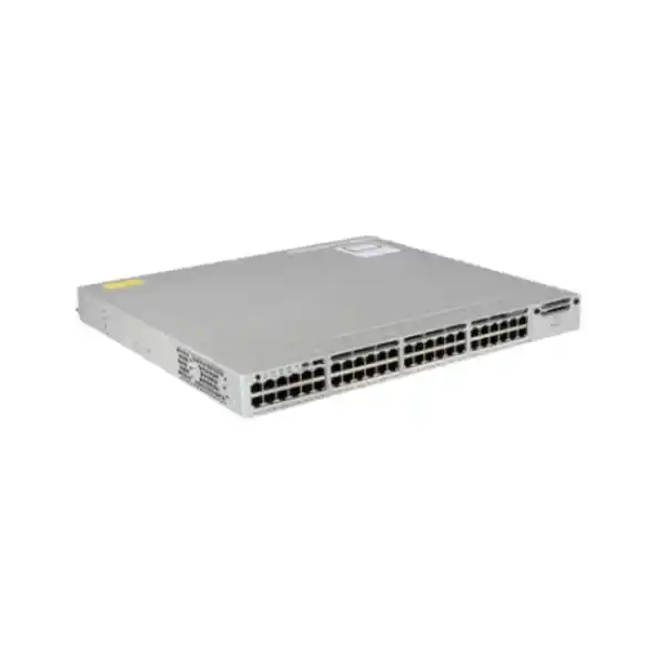
Cisco Catalyst C9200-48PB Network Switch
The Cisco Catalyst C9200-48PB is a 48-port Gigabit Ethernet PoE+ access switch designed for business-critical campus, branch and distributed enterprise networks. It combines high-density powered access, modular uplink options, StackWise-160 resiliency, Cisco IOS XE operations and enhanced virtual-network capability in a compact 1RU platform. For UAE organizations modernizing office floors, schools, healthcare sites, hospitality properties, retail locations, warehouses or multi-site branches, the C9200-48PB provides a practical balance of access-layer scale, operational consistency and lifecycle control.
Enhanced-VN 48-port Catalyst 9200 PoE+ platform. The commonly listed orderable software variant is C9200-48PB-A with Network Advantage.
Select the uplink module to match the distribution layer, fiber plant, optics strategy and growth plan rather than being locked into a fixed uplink layout.
Field-replaceable power architecture supports redundant designs and higher available PoE when a compatible secondary supply is installed.
Built for endpoints, IP telephony, cameras, Wi-Fi access points, IoT devices and user access at office, campus and branch locations.
Direct answer: what is the Cisco Catalyst C9200-48PB?
The Cisco Catalyst C9200-48PB is a stackable, modular-uplink, 48-port 10/100/1000 Ethernet switch with full PoE+ access-port capability. It belongs to the Catalyst 9200 family and is positioned as an enterprise access-layer platform rather than a simple unmanaged or lightly managed edge switch. The PB model is differentiated by enhanced virtual-network scale, supporting up to 32 virtual networks in the applicable Network Advantage configuration, making it useful where segmentation is expected to extend beyond a small number of traditional VLAN-only zones.
In practical terms, the switch is intended to aggregate many powered edge devices while preserving Cisco enterprise features for resiliency, security, telemetry, automation and Layer 3 services. A standard C9200-48PB chassis uses a default PWR-C6-1KWAC primary power supply and provides 740 W of available PoE power with that single supply. Adding a second compatible 1 kW AC supply can raise available PoE power to 1,440 W. The platform supports StackWise-160, field-replaceable fan modules, 4 GB DRAM, 4 GB flash and a modular uplink slot. Because the exact commercial bundle also includes choices for software subscriptions, support coverage, uplink modules, optics, stack hardware and secondary power, procurement should be treated as a bill-of-materials exercise rather than buying a chassis name alone.
Why the C9200-48PB matters in modern UAE access networks
Access switching is no longer just a question of connecting desktop computers. A single communications room may now serve IP handsets, Wi-Fi access points, network cameras, door controllers, time-and-attendance devices, digital signage, building-management gateways, printers, thin clients, meeting-room systems, IoT sensors and conventional user endpoints. Many of those devices require both data and power, and many belong to different security zones. The C9200-48PB addresses this convergence by combining a dense 48-port PoE+ edge with segmentation, routing, policy and telemetry capabilities expected from Cisco enterprise switching.
For projects in Dubai, Abu Dhabi, Sharjah and other UAE locations, physical and operational design considerations often matter as much as raw port count. High device density can rapidly consume PoE headroom, while dual-uplink architectures, redundant power and stacking can determine whether a single component failure becomes a user outage. The C9200-48PB provides a pathway to engineer those concerns directly into the access layer. The modular uplink approach lets designers select optics and uplink speeds that align with existing distribution switches instead of accepting a fixed uplink compromise. StackWise-160 allows multiple compatible switches to operate with a high-bandwidth stack fabric, which simplifies logical management and can support resilient uplink designs.
The PB variant is particularly relevant where the network roadmap includes deeper segmentation. Traditional office switching may use only a few VLANs, but modern organizations frequently separate corporate users, voice, wireless infrastructure, cameras, guest access, operational technology, building systems and restricted service networks. Cisco lists the C9200-48PB with enhanced virtual-network support of up to 32 virtual networks, compared with the smaller virtual-network scale on several standard C9200 variants. This does not mean every deployment should use all 32, but it provides architectural headroom for organizations adopting structured segmentation or software-defined access practices.
Verified C9200-48PB hardware and scale profile
| Access ports | 48 × 10/100/1000 copper ports with PoE+ capability |
| Virtual networks | Up to 32 VNs on the C9200-48PB enhanced-VN model |
| Stacking bandwidth | 160 Gbps StackWise support |
| Switching capacity | 176 Gbps standalone; 336 Gbps switch capacity with stacking |
| Forwarding rate | 130.95 Mpps standalone; up to 250 Mpps with stacking |
| MAC address scale | 32,000 total MAC addresses |
| IPv4 route scale | 14,000 total IPv4 routes including direct and indirect entries; 4,000 IPv4 routing entries |
| IPv6 routing entries | 2,000 |
| Flexible NetFlow scale | 16,000 flows for Gigabit Ethernet C9200 models |
| Packet buffer | 6 MB on the 24/48-port Gigabit Ethernet C9200 platform class |
| System memory | 4 GB DRAM and 4 GB flash |
| SVIs / VLAN IDs | Up to 512 SVIs and 4,094 VLAN IDs |
| Jumbo frames | Up to 9,198 bytes |
| Default AC power supply | PWR-C6-1KWAC |
| Available PoE power | 740 W with one default 1 kW AC supply; 1,440 W with a compatible second 1 kW AC supply |
| Physical dimensions | 1.73 × 17.5 × 13.8 in chassis; approximately 4.4 × 44.5 × 35.0 cm, with approximately 5.5 kg chassis weight |
Published platform figures can vary by software release, license level, topology and configured feature set. Final design should validate the current Cisco release notes, ordering guide and selected bill of materials.
48-port PoE+ access: designing the endpoint layer correctly
The most visible feature of the C9200-48PB is its set of 48 Gigabit Ethernet copper access interfaces with PoE+. Each port can support standard Ethernet endpoint connectivity and can provide power to compatible powered devices, subject to the switch’s total available PoE budget and the negotiated power class. This creates a clean access-layer design for environments where many devices would otherwise require local AC adapters. Eliminating individual power bricks simplifies desk installation for phones, eases camera placement, reduces electrical clutter around ceiling-mounted wireless access points and centralizes power protection behind the network rack’s UPS infrastructure.
A 48-port label does not automatically mean that all forty-eight powered devices can draw their maximum PoE+ power at the same time. The design must consider aggregate power. With the standard PWR-C6-1KWAC, Cisco specifies 740 W of available PoE power for the C9200-48PB. Dividing that figure evenly across forty-eight ports yields an average budget of roughly 15.4 W per port, although actual allocation is device-driven rather than evenly distributed. That is often sufficient for mixed estates containing phones, low-to-medium power cameras and selected access points, but it may be insufficient when many devices are near the upper PoE+ limit. Adding a second compatible 1 kW AC supply raises the available PoE figure to 1,440 W, which is equivalent to 30 W across all forty-eight ports in aggregate and therefore enables full PoE+ density under the documented power design.
For procurement, FourTeck recommends building a port-by-port power worksheet rather than applying a broad percentage. List the powered device model, IEEE power class, expected steady-state draw, startup peak where relevant, cable distance, device quantity and expected future additions. Separate critical endpoints such as security cameras or access-control devices from noncritical loads such as desk phones if the switch will operate with power redundancy. This helps determine whether the second PSU is being installed primarily for hardware resilience, for PoE capacity, or for both. Those are different design objectives and should be reflected in the rack power plan and UPS sizing.
When planning a new access layer across several communications rooms, the same methodology can be standardized through FourTeck IT Services UAE, so each closet has a documented endpoint inventory, PoE headroom target, uplink requirement and redundancy policy. This avoids the common problem of purchasing a capable switch but undersizing the power supplies, UPS, PDU outlets or cooling capacity needed to operate it reliably.
Modular uplinks: matching the switch to the distribution layer
The modular-uplink architecture is one of the strongest reasons to choose a full C9200 model rather than a fixed-uplink variant. Instead of embedding a permanent uplink configuration into the chassis, Cisco provides network-module choices so the access switch can be aligned with the actual distribution design. Current Catalyst 9200 documentation lists modular uplink options spanning 1 Gigabit, 10 Gigabit, 25 Gigabit and 40 Gigabit Ethernet on supported configurations, including modules such as four-port 1G, four-port 10G, two-port 25G and two-port 40G options. The correct module is selected according to the distribution switch, optics, fiber type, required aggregate bandwidth, redundancy model and expected lifecycle.
For many office deployments, dual 10G uplinks provide a practical balance between cost and headroom. A 48-port access switch with many user devices rarely drives all ports at full line rate simultaneously, so two diverse 10G uplinks—typically arranged as an EtherChannel to a resilient distribution layer or split across stack members—can provide strong performance. However, high-density wireless, video surveillance, storage-adjacent users or converged networks may justify higher uplink capacity. The 25G or 40G options can be useful when the upstream platform supports those interfaces and when the fiber plant, transceivers and redundancy design are aligned with that speed.
Uplink selection is not only about bandwidth. It also affects optics cost, patching type, fiber polarity, distance limits, spare strategy and compatibility with existing core or distribution equipment. A project using short multimode fiber inside a building may choose a different optic set from a campus link crossing between buildings, while a data-room deployment using direct-attach cabling may have another solution entirely. The transceiver must be supported by the chosen network module and software release, and the distribution-side optic must use a compatible standard.
A good quotation therefore identifies the uplink module and the exact required transceiver quantity rather than listing only the base switch. This is especially important when multiple C9200 stacks are being deployed, because missing uplink optics can delay commissioning even when all chassis have arrived. FourTeck UAE can align the switch BOM with existing switching infrastructure and fiber documentation through the wider FourTeck UAE technology portfolio.
StackWise-160 and resilient access-layer design
The C9200-48PB supports Cisco StackWise-160, giving the platform up to 160 Gbps of stack bandwidth. Stacking allows multiple compatible switches to operate as a coordinated system, which can simplify management, improve resiliency and reduce the operational complexity of treating every access switch as a completely independent island. From an administrator’s perspective, a properly designed stack can provide a single logical control and management context, while the physical stack members contribute their ports and power resources according to the platform architecture.
The value of stacking becomes clearest when failure scenarios are examined. In a standalone design, the loss of an access switch removes all attached endpoints on that chassis. Stacking does not eliminate that physical reality, but it enables uplink diversity and system-level resiliency so the failure of a single uplink or the maintenance of one stack member does not necessarily isolate the entire access block. Critical endpoints can also be distributed across members when cabling and endpoint location allow, and upstream EtherChannels can be spread across different stack members to avoid a single-member uplink dependency.
Stack design must include the stack cables themselves, the physical cable path and the topology. A resilient ring is typically preferred over a simple chain because the ring preserves an alternate stack path if one stack link is interrupted. The rack elevation should reserve realistic cable-bend space, and stack members should be numbered and labeled consistently before production handover. Engineers should also confirm software compatibility and supported mixed-stack combinations. Cisco specifically notes that the C9200-24PB-A and C9200-48PB-A enhanced-VN SKUs should not be stacked with C9200 models limited to four virtual networks. This point matters in refresh projects where an organization intends to add a PB switch to an older existing C9200 stack.
Stacking should not be used merely because the feature exists. Very small remote sites may be better served by a single switch with resilient uplinks, while larger floors may benefit from two or more stacked members. The correct choice depends on endpoint count, maintenance windows, spare strategy, uplink architecture, failure-domain policy and cabling. A design review should document what the stack is intended to survive and which components remain single points of failure.
UADP 2.0 mini architecture: why the forwarding engine matters
Cisco’s Catalyst 9200 architecture is built around the UADP 2.0 mini application-specific integrated circuit. UADP stands for Unified Access Data Plane, and the design is intended to provide a programmable forwarding foundation for enterprise access switching. For the C9200 class, the ASIC integrates the packet-processing pipeline and an embedded CPU complex while being optimized for the scale, power profile and throughput expected at the access layer. Cisco’s architecture documentation describes the UADP 2.0 mini as a system-on-chip design using a programmable pipeline and an embedded quad-core ARM CPU.
This architecture matters because switching performance is not determined only by the speed labels printed next to ports. Enterprise networks require classification, access-control decisions, forwarding lookups, QoS actions, telemetry and packet rewriting to occur efficiently while traffic moves through the switch. The UADP architecture is designed to execute these functions in hardware so feature use does not require every packet to be handled by the general-purpose CPU. That separation is essential for predictable forwarding under load.
The C9200 platform scale reflects that access-focused design. Cisco lists 32,000 MAC addresses for C9200 SKUs, up to 14,000 total IPv4 routes including direct and learned routes, 2,000 IPv6 routing entries, 1,000 multicast routing scale, 1,000 QoS scale entries and 1,600 ACL scale entries. The Gigabit Ethernet models include 6 MB of packet buffer and support 16,000 Flexible NetFlow entries. These numbers are not merely marketing specifications; they define the practical boundaries within which a design should operate.
For a normal office access layer, those limits are generous because most forwarding occurs at Layer 2 with a manageable number of VLANs and endpoint MAC addresses. In a routed-access, highly segmented or telemetry-heavy design, however, scale becomes more important. Engineers should compare expected routes, ACLs, SVIs, NetFlow records and segmentation requirements against the supported hardware tables rather than assuming a campus switch is unlimited. The C9200-48PB is strongest when used for the role it was designed for: secure, feature-rich enterprise access with predictable hardware forwarding and manageable policy scale.
Segmentation and the C9200-48PB enhanced virtual-network model
Segmentation has become a central access-layer requirement because a modern switch serves endpoints with very different trust levels. Corporate laptops, guest users, surveillance cameras, printers, phones, door controllers, building systems and unmanaged IoT devices should not automatically share the same security domain. Traditional VLANs remain important, but enterprise designs increasingly add policy-based segmentation, security group constructs, VRF separation and software-defined access workflows to reduce lateral movement and create cleaner operational boundaries.
The C9200-48PB is the enhanced-VN member of the 48-port Gigabit PoE+ C9200 family. Cisco specifies up to 32 virtual networks for the PB models, a substantial increase over the four-VN scale listed for several standard modular C9200 models. That makes the C9200-48PB relevant when an organization wants an access switch with more room for logically isolated business or device domains. A hospital, for example, may separate clinical users, administrative users, voice, guest wireless, cameras, biomedical devices and facilities systems. A hotel may separate guest services, property-management systems, staff operations, surveillance, IP telephony, access control and building automation.
The number of virtual networks should still be governed by a coherent policy model. Excessive segmentation without clear ownership can make troubleshooting, route leaking, DHCP design, firewall policy and identity mapping unnecessarily complicated. The objective is not to maximize the number of segments but to create security boundaries that correspond to real risk, compliance and operational requirements. The C9200-48PB simply gives the access layer more segmentation capacity when those boundaries are justified.
In a layered enterprise design, the switch’s segmentation should align with upstream firewall and security policy. FourTeck’s Firewall Dubai practice can be used to coordinate access-layer segmentation with inter-zone inspection, internet security and policy enforcement, so VLANs or virtual networks are not created in isolation from the firewall rules that ultimately control communication between them.
Cisco IOS XE operations, programmability and lifecycle control
The Catalyst 9200 family runs Cisco IOS XE, giving network teams a common operational framework across a broad portion of Cisco’s enterprise switching portfolio. IOS XE provides the familiar command-line workflow required by traditional network operations while also supporting model-driven automation and modern management integrations. This combination matters for organizations that are moving from device-by-device configuration toward standardized templates, API-based provisioning, controller-driven operations or infrastructure-as-code practices.
A production deployment should begin with a software lifecycle policy. The selected IOS XE release must be supported on the platform, compatible with the required feature set and aligned with the organization’s standard release train. Engineers should review Cisco release notes for open caveats, resolved defects, supported optics, stack behavior and licensing requirements before upgrade windows. In multi-switch environments, keeping access stacks on a controlled set of approved versions reduces operational variation and makes incident response easier.
Automation can provide substantial value at 48-port scale because the repetitive elements of access switching are significant. Interface descriptions, voice VLANs, access VLANs, 802.1X policy, DHCP snooping, spanning-tree edge settings, storm control, QoS trust boundaries, port security conventions and monitoring can all be templatized. The goal is consistency: port 17 on one floor should not behave differently from port 17 on another floor unless there is a documented requirement. Standardized configurations also make auditing easier because deviations become visible.
Telemetry and observability should be designed alongside configuration. Flexible NetFlow support, logging, SNMP or model-driven telemetry, time synchronization and controller integration can provide the data required to investigate performance or security events. The switch is capable of supporting a mature operations model, but value comes from integrating it into monitoring, configuration backup, identity, alerting and change-management processes. A Catalyst access switch deployed without those operational controls is still functional, but the organization is not using the platform to its full enterprise potential.
Licensing: Network Advantage, Cisco DNA and current subscription considerations
Licensing is a critical part of the C9200-48PB bill of materials. Cisco’s current ordering information lists C9200-48PB-A as the 48-port PoE+ enhanced-VRF model with Network Advantage. Cisco also documents perpetual Network Essentials and Network Advantage feature tiers together with term-based software subscriptions. Network Advantage adds capabilities beyond the foundational Network Essentials level, particularly for more advanced routing, segmentation, multicast, scale and security scenarios. Because the PB SKU is specifically associated with the enhanced virtual-network design, Network Advantage is central to understanding the platform’s intended positioning.
Cisco documentation also references Cisco DNA subscriptions in Essentials and Advantage tiers with three-, five- and seven-year terms, while newer commercial models include the Cisco Networking Subscription and unified Switching Essentials or Switching Advantage tiers. The naming and ordering framework can change over time as Cisco evolves licensing programs, so buyers should not assume that an older quote, renewal or subscription part number remains the correct commercial selection for a new purchase. The quotation date, Cisco program, software release, customer Smart Account and intended management platform all matter.
Smart Licensing should also be planned before deployment. The organization needs to know which Cisco account will own the entitlements, who has administrative access, whether the environment uses cloud-connected or supported on-premises licensing workflows and how renewals are governed. This prevents a common operational problem in which a technically correct switch is commissioned but the license ownership, subscription alignment or support contract is attached to the wrong account or cannot be managed by the operations team.
For procurement teams, the safest approach is to request a complete commercial BOM that explicitly identifies the switch hardware, perpetual network tier, current required subscription, duration, support service, uplink module, optics, stack kit, power supplies and accessories. FourTeck can validate the current ordering structure at quotation time rather than relying on static legacy part numbers copied from a previous project.
Power redundancy, UPS sizing and thermal planning
A PoE switch concentrates electrical load in the communications room, so power planning must go beyond the switch’s nominal PSU wattage. The default C9200-48PB configuration uses a 1 kW AC power supply and makes up to 740 W available to powered devices. When a second compatible 1 kW AC supply is installed, Cisco specifies up to 1,440 W available PoE. The difference between PSU rating and PoE budget accounts for the switch’s own system power and conversion characteristics. Engineers should therefore size rack PDUs and UPS capacity using the actual switch and endpoint load model, not by simply multiplying the chassis count by 740 W or 1,440 W.
Redundant power design requires clear failure assumptions. If both supplies are installed but both connect to the same PDU, same UPS or same electrical circuit, the switch gains PSU redundancy but not true source diversity. A stronger design connects each PSU to a separate rack PDU, preferably backed by independent UPS feeds where the building infrastructure supports it. The availability requirement of the site determines whether that additional complexity is justified. A small branch may accept a single source, while a hospital floor, security network or revenue-critical office may require much stronger power-path resilience.
Thermal planning matters because PoE energy eventually becomes heat across the switch, cabling and powered endpoints. Cisco’s C9200 chassis uses front/side-to-rear airflow and field-replaceable fans on modular C9200 models. The rack should provide unobstructed intake and exhaust clearance, while the room cooling system should be sized for all active networking, UPS and server equipment. Dense racks should avoid placing equipment in a way that recirculates hot exhaust into switch intakes.
Where the access switch shares a room with compute, storage or server infrastructure, coordination with the Server Dubai team can help align rack elevation, UPS capacity, PDU outlet planning and cooling assumptions. This is particularly useful in branch server rooms where networking and compute are installed within the same compact rack and compete for the same electrical and thermal envelope.
Security controls at the access edge
The access switch is the first trusted network device encountered by many endpoints, which makes it an important enforcement point. Security design should begin with physical and logical identity. Unused ports should be administratively disabled or placed into a restricted provisioning state. Active ports should have explicit access roles, descriptive labels and predictable policy. For user-facing networks, IEEE 802.1X and identity-based access can be combined with fallback methods for devices that cannot perform supplicant authentication, while device profiling and policy systems can help distinguish managed clients from phones, cameras and IoT endpoints.
Layer 2 protection remains essential even in advanced networks. DHCP snooping can help prevent unauthorized DHCP servers, Dynamic ARP Inspection can use trusted binding information to reduce ARP spoofing risk, and IP Source Guard can restrict traffic based on validated address bindings. Spanning-tree protections such as BPDU Guard are valuable on edge ports to prevent accidental loops caused by unmanaged switches. Storm control can limit the impact of broadcast or multicast anomalies. These controls should be deployed through tested templates because an inconsistent configuration can create both security gaps and troubleshooting complexity.
Segmentation then reduces the blast radius if an endpoint is compromised. Voice devices, cameras, guest access and operational technology should not automatically share unrestricted east-west connectivity with business workstations. The C9200-48PB’s enhanced virtual-network capacity can be part of a broader architecture in which identity, VLANs, VRFs or software-defined segmentation determine which services each endpoint can reach. Where traffic crosses trust zones, upstream firewalls or distributed policy controls should enforce the required application rules.
Management-plane protection is equally important. Administrative access should use encrypted protocols, authenticated operators, centralized AAA where appropriate and restricted management networks. Time synchronization, logging and configuration backups should be mandatory so events can be correlated during investigations. The switch should not be exposed to unnecessary management sources, and software should be maintained within a supported lifecycle. Security is therefore a combination of platform capability, configuration discipline and operational governance rather than a single checkbox feature.
QoS, voice, wireless and real-time traffic design
A converged access switch must carry traffic with very different latency and loss characteristics. A file transfer can tolerate delay and retransmission far more easily than a voice call, interactive video session or wireless control exchange. Quality of Service should therefore be engineered from the endpoint edge through the uplink path. The C9200 platform supports enterprise QoS functions and provides hardware scale for approximately 1,000 QoS entries in the C9200 class, allowing traffic to be classified, marked, queued and policed according to the network policy.
For IP telephony, the switch often provides both data access for a computer and a separate voice VLAN for a handset on the same physical port. The phone may be powered by PoE+ while advertising or consuming QoS markings for voice media and signaling. Trust boundaries must be defined carefully so an unmanaged user device cannot simply mark all traffic as high priority. In well-designed deployments, the switch identifies trusted device types or interfaces and applies a consistent policy that protects real-time traffic without starving business data.
Wireless access points introduce another dimension. Each AP can aggregate many users and applications behind one wired access port. Although the C9200-48PB’s downlinks are 1 Gigabit rather than multigigabit, it can be appropriate for wireless deployments where AP requirements and expected throughput remain within that access speed. Where high-end Wi-Fi 6/6E or newer APs require multigigabit Ethernet, a C9200PXG or another multigigabit-capable platform may be the better choice. The switch should therefore be selected from the endpoint requirement backward rather than assuming every PoE+ switch is interchangeable.
Video surveillance can also produce sustained uplink load because dozens of cameras transmit continuously toward recording servers. A camera VLAN with appropriate multicast, QoS and security design should be sized together with the uplink and storage architecture. The aggregate bitrate of all cameras, retention design and recording topology can determine whether 10G or higher uplinks are justified. This is another example where access-port count alone is not enough to select a switch.
Layer 2 and Layer 3 scale for campus and branch deployments
The C9200-48PB provides substantial Layer 2 scale for an access switch. Cisco lists support for 4,094 VLAN IDs, 512 switched virtual interfaces, 128 PVST instances and up to 13,000 spanning-tree virtual ports under the documented platform limits. The total MAC address table is listed at 32,000 entries. These capacities support large endpoint populations and segmented access designs, but the practical network should remain structured rather than approaching hardware limits without a clear reason.
Layer 3 capability allows the switch to participate in routed-access designs or perform local inter-VLAN routing where appropriate. Cisco lists up to 14,000 total IPv4 routes for the C9200 class, consisting of direct and indirect route capacity, with 4,000 IPv4 routing entries and 2,000 IPv6 routing entries. The exact protocol and advanced feature availability depends on the installed Network license and software release. For the PB model, Network Advantage is the relevant orderable tier and is suited to deployments that require more advanced routing and segmentation functions.
A routed-access design can reduce spanning-tree dependency by using Layer 3 boundaries closer to the edge, but it also changes DHCP relay, first-hop gateway, summarization, troubleshooting and security policy. Conversely, a traditional Layer 2 access design centralizes routing at the distribution layer and may be easier to operate in smaller environments. The C9200-48PB can participate in either model, but the architecture should be chosen deliberately based on operational maturity and site scale.
Jumbo-frame support up to 9,198 bytes provides additional flexibility for applications that use larger MTUs, although enabling jumbo frames should be end-to-end and application-driven. A mismatch in MTU across access, distribution, firewall or WAN paths can create difficult-to-diagnose failures. Standard user access generally works well with conventional Ethernet MTU values, so jumbo settings should not be changed merely because the switch supports them.
Performance: interpreting 176 Gbps switching and 130.95 Mpps forwarding
Cisco specifies 176 Gbps of standalone switching capacity and 130.95 million packets per second of forwarding performance for the C9200-48PB. With stacking, the published switch capacity rises to 336 Gbps and forwarding rate to 250 Mpps. These figures describe the platform’s ability to move traffic through the switching fabric and are more meaningful when interpreted alongside port speeds, uplink selection, stack design and traffic patterns.
Most access networks are oversubscribed by design. Forty-eight 1G edge ports could theoretically represent 48 Gbps of one-direction access traffic, but normal users rarely transmit at line rate simultaneously. The uplink therefore does not need to equal the simple sum of access port labels. Instead, designers estimate concurrency and traffic profiles. General office traffic may use modest average bandwidth with bursts, while camera networks produce sustained streams, backup windows create heavy flows and wireless APs can aggregate many clients. The correct uplink speed emerges from those workloads.
Packet-per-second capacity is especially relevant to traffic made of small packets, because forwarding engines can encounter much higher packet rates even when raw bandwidth is below the line-rate number. Voice, control protocols and some security workloads may produce small packets. The platform’s hardware forwarding is designed to sustain enterprise access behavior, while QoS, ACL and NetFlow resources provide the policy and observability required around that forwarding.
For sizing, the best method is to use measured data from the existing network where possible. Interface utilization, NetFlow, application telemetry and uplink peak statistics provide stronger evidence than assumptions. New greenfield sites can model expected users, cameras, APs and applications, then add growth headroom. The resulting design should reserve enough uplink and stack capacity to absorb normal peaks and a realistic failure scenario without excessive congestion.
Physical deployment, rack integration and cabling standards
The C9200-48PB is a standard 1RU rack-mount access switch. Cisco lists chassis dimensions of approximately 1.73 × 17.5 × 13.8 inches, or 4.4 × 44.5 × 35.0 centimeters, with an approximate chassis weight of 5.5 kilograms. With fan and power components installed, rear clearance requirements increase, so rack depth and cable management should be checked rather than assuming that any shallow wall cabinet will be suitable. The switch’s airflow direction also needs to match the cabinet’s ventilation strategy.
Structured cabling should be certified for the intended Ethernet application and terminated into clearly labeled patch panels. Because the C9200-48PB access interfaces are 1G copper, Category 5e can support Gigabit Ethernet within standards-based distance limits, while Category 6 or better is often selected for new installations to improve long-term cabling capability. For PoE deployments, cable bundle size, conductor gauge, ambient temperature and pathway density should be considered because higher aggregate current can raise bundle temperature.
Rack organization has a direct effect on serviceability. Forty-eight access ports create a large patching field; placing horizontal cable managers between switches and patch panels can reduce strain and make port tracing easier. Short, consistent patch-cord lengths improve appearance but should not be so tight that service loops disappear. Power cords should be routed separately from data where practical, and redundant PSU feeds should be labeled according to PDU and UPS source.
Before handover, each access port should have an interface description mapped to room, outlet or endpoint identity. Stack members, uplink fibers, optics, power feeds and console access should all be documented. Good labeling reduces mean time to repair because technicians can identify the correct cable or switch without relying on trial and error. In large UAE deployments with many branch rooms, consistent rack and labeling standards are often more valuable operationally than small differences in hardware cost.
Deployment scenarios for the C9200-48PB
Corporate office floor
A single switch or two-member stack can serve user desks, Cisco or third-party IP phones, printers, meeting-room devices and ceiling access points. Voice and corporate data can use separate access policies, while guest and IoT traffic is segmented. Redundant 10G uplinks to distribution switches provide a strong default for many office floors. The PoE worksheet should include phones and APs plus at least 20–30 percent operational headroom where budget permits.
Video surveillance access
Forty-eight PoE+ ports can support a dense camera aggregation point, but the design must calculate both total camera wattage and aggregate recording bitrate. Continuous video can create sustained uplink traffic, so the uplink module should be sized against actual codec, resolution, frame rate and retention design. Camera networks should be isolated from general users and routed through controlled security policy.
Education campus
Classrooms and administrative areas can combine PCs, phones, Wi-Fi APs, interactive displays and security devices. Enhanced virtual-network scale helps separate student, faculty, guest, voice, CCTV and facilities services. Stacking can simplify access blocks in larger communications rooms, while consistent IOS XE templates support repeatable configuration across multiple buildings.
Hospitality and retail
Hotels and retail sites often mix guest-facing services with point-of-sale, cameras, staff systems, access control and building management. A structured segmentation plan is essential. The C9200-48PB provides access density and PoE capability, while upstream security and WAN policy can keep revenue-critical systems separated from guest or IoT networks.
Warehouse and logistics
A warehouse communications room may connect cameras, Wi-Fi APs, handheld-device infrastructure, printers, access-control equipment and office users. The most important planning inputs are cable reach, environmental conditions, fiber uplink diversity, AP density and camera bandwidth. The switch should remain in a suitable controlled cabinet or room within its operating specifications.
Regional branch standard
Organizations operating across the Middle East and Africa can standardize on a repeatable access-switch profile that includes the same VLAN model, authentication, monitoring, QoS, uplink optics and support terms. FourTeck can extend procurement and deployment coordination through its Africa technology coverage where regional projects require consistent engineering across multiple countries.
C9200-48PB versus C9200-48P, C9200-48PL and C9200-48PXG
Several Catalyst 9200 models appear similar because they share the same general chassis family and 48-port access density. The differences matter. The C9200-48P is a full PoE+ 48-port model with modular uplinks and StackWise support, but Cisco lists the standard C9200-48P with lower virtual-network scale than the PB enhanced-VN model. The C9200-48PB is therefore the stronger choice where segmentation and SD-Access virtual-network headroom are important. It is not merely a different power configuration.
The C9200-48PL is a partial-PoE model. It is appropriate when many ports are data-only or when the total powered-device requirement is lower. Its default power design is smaller than the 48P/48PB full-PoE platforms. Choosing a PL model solely because it is less expensive can create a future constraint if cameras, access points or phones are added later. A port-count and PoE-load forecast should therefore precede the hardware choice.
The C9200-48PXG adds multigigabit capability on selected access ports and is better suited to high-throughput wireless access points or other devices that can exceed 1G Ethernet. If the project includes Wi-Fi access points with 2.5G, 5G or 10G Ethernet interfaces and the application actually needs those speeds, the PXG family may be more appropriate. Conversely, when all edge devices are 1G and the key requirement is enhanced segmentation, the PB model can provide a cleaner value proposition.
The practical selection rule is simple: choose the switch based on endpoint speed, PoE density, segmentation scale, uplink requirement and license level together. Avoid selecting by port count alone. A technically correct product recommendation often requires only a short worksheet of those five factors, but ignoring any one of them can produce either unnecessary cost or an under-capable deployment.
PoE sizing methodology for 48 powered ports
PoE planning should start with the endpoint list, not the switch specification. Create a table with one row for every powered-device model and include quantity, negotiated power requirement, maximum consumption, normal consumption and business criticality. For IP phones, include any sidecar modules or expansion screens that increase draw. For access points, use the vendor’s required PoE standard for full radio operation, not the lowest boot power. For cameras, include heaters, infrared illumination, pan-tilt-zoom motors or other features that can increase consumption under certain conditions.
Next, calculate the worst credible aggregate draw rather than simply adding nameplate maxima if those maxima cannot occur concurrently. A conservative enterprise design may still choose to size for full maximum, but the assumption should be documented. Add headroom for replacement devices and growth. If the resulting figure is below 740 W with a comfortable margin, one default AC supply can meet the PoE capacity requirement, although the design may still add a second supply for redundancy. If the required power approaches or exceeds 740 W, the second 1 kW AC supply becomes necessary to reach the documented 1,440 W available PoE capacity.
Then examine the failure state. A switch with two PSUs may have enough total PoE when both are operating but lose available power if one supply or electrical feed fails. The business must decide whether every powered endpoint must remain operational during that failure. If the answer is yes, the design should ensure that surviving power capacity and policy can sustain the critical device set. If the answer is no, the switch can prioritize high-value ports and shed noncritical loads. This is a resilience decision, not simply an electrical calculation.
Finally, align the PoE model with UPS runtime. A 1,000 VA UPS is not automatically sufficient for a heavily loaded PoE switch, and a 1,440 W PoE design can materially increase battery and cooling requirements. The UPS must support the combined real load, desired runtime, power factor and any additional rack equipment. For branches with cameras and access-control devices, longer runtime may be required than for ordinary user phones.
Network sizing methodology: ports, uplinks, stack members and growth
The first sizing input is usable port demand. A 48-port switch should not be filled to forty-eight active endpoints on day one unless the organization accepts immediate expansion work. Reserve capacity for moves, adds, replacements, access points, cameras and temporary devices. A common design approach targets roughly 70–85 percent steady-state port utilization, depending on the predictability of the environment. For a floor expected to stabilize at sixty powered endpoints, two 48-port switches may be more appropriate than forcing every endpoint into one chassis plus ad hoc small switches.
The second input is traffic mix. General user access tends to be bursty, whereas surveillance and backup traffic can be sustained. Estimate northbound traffic during the busiest period and during failure conditions. Two 10G uplinks may be ample for normal office use but should still be checked against simultaneous high-bandwidth wireless or camera loads. Where the C9200-48PB is used in a stack, understand how traffic enters and leaves each member and whether upstream EtherChannels are distributed across members.
The third input is policy and feature scale. Count VLANs, virtual networks, SVIs, routing entries, ACL complexity and expected NetFlow records. Most access deployments will remain comfortably below C9200 limits, but highly segmented multi-tenant or policy-heavy environments should verify scale explicitly. The PB model’s 32-VN capability is valuable only if the surrounding control plane, routing and security architecture is also designed to support that segmentation cleanly.
The fourth input is lifecycle growth. Consider new Wi-Fi standards, higher-resolution cameras, additional building systems and organizational expansion. If the roadmap includes widespread multigigabit wireless within the switch’s service life, a PXG or newer multigigabit platform may offer better long-term economics. If endpoints are expected to remain 1G while segmentation requirements grow, the C9200-48PB remains a strong fit. Good sizing aims to avoid both premature replacement and overbuying features that will never be used.
Monitoring, telemetry and troubleshooting workflow
Reliable access switching requires visibility into both the switch and the endpoints connected to it. At minimum, operations teams should monitor interface state, error counters, utilization, PoE consumption, power-supply status, fan health, stack state, CPU, memory, temperature and critical logs. Monitoring should distinguish between a physical port failure, a cable fault, an endpoint power problem and an authentication failure because each condition has a different troubleshooting path.
Flexible NetFlow can add traffic visibility by summarizing conversations and applications. Cisco lists 16,000 Flexible NetFlow entries on 24- and 48-port Gigabit Ethernet C9200 models. Used selectively, NetFlow can reveal which endpoints are generating unexpected traffic, whether a camera VLAN is reaching the expected recorder, or whether an uplink peak is caused by backup traffic rather than user browsing. Exporters and collectors should be sized so telemetry does not become another unmanaged system.
Logging and time synchronization are essential for incident analysis. Every switch should use consistent NTP sources and send important events to centralized logging. Authentication failures, spanning-tree changes, power events, stack member transitions, link flaps and configuration changes become far more useful when timestamps are accurate across switches, firewalls, servers and identity systems. Configuration archives should also be maintained so engineers can compare current and previous versions during root-cause analysis.
For large estates, controller-based management and automation can add assurance and standardized policy, but the organization should still maintain a clear break-glass troubleshooting method. Engineers need console access procedures, credential governance and documented recovery steps for situations where centralized systems are unreachable. Monitoring architecture should therefore combine central visibility with local recoverability.
UAE procurement considerations: what should be included in the quotation?
A professional quotation for the Cisco Catalyst C9200-48PB should identify more than the switch name. At minimum, the bill of materials should specify the exact orderable chassis SKU, software tier, subscription term, uplink network module, transceiver type and quantity, stack kit if required, stack cables, primary and secondary power supplies, power cords compatible with the site, support coverage and any rack accessories. If spare optics, spare PSUs or cold-spare switches are required, they should be separated clearly from production quantities.
Lead time and lifecycle status should be checked at quotation stage because enterprise networking products are subject to supply-chain variation, regional stock conditions and Cisco lifecycle announcements. A technically preferred configuration may not be the most practical if a required module or optic has a substantially different availability profile. Equivalent design alternatives should be evaluated only when they preserve the required functionality, not simply because another model is in stock.
Support services should match business criticality. A branch office with local spare hardware may tolerate next-business-day replacement, while a hospital, hotel or financial site may require a stronger support plan. The support decision should also consider whether the customer has in-house Cisco expertise or depends on an integration partner for troubleshooting. Hardware replacement alone does not solve configuration, routing, authentication or design issues.
Regional procurement can also include staging. Pre-deployment services may cover software standardization, configuration templates, stack assembly, labeling, burn-in checks, asset recording and shipment by site. For larger rollouts, the FourTeck global team can support multi-location coordination while UAE delivery remains aligned with local project requirements.
Recommended bill-of-materials logic
1. Base switch
Confirm C9200-48PB-A or the current Cisco equivalent commercial identifier for the required Network Advantage enhanced-VN configuration. Do not substitute C9200-48P, C9200-48PL or C9200L without checking the effect on virtual-network scale, PoE capacity and uplink flexibility.
2. Software entitlement
Select the current required Cisco software subscription and term, aligned with the Network Advantage hardware/software entitlement and the customer’s Smart Account. Verify whether the project uses Cisco DNA, Catalyst software subscription or Cisco Networking Subscription ordering at the time of purchase.
3. Uplink module
Choose 1G, 10G, 25G or 40G uplink capability based on upstream ports, fiber type, optic distance and traffic sizing. The network module should be written explicitly into the quotation, together with spare strategy if the site is critical.
4. Optics and cabling
Specify compatible transceivers, patch leads and fiber standard. For stacking, include the required StackWise hardware and cable lengths. For copper access, include patching quantities and certification requirements if the project scope covers structured cabling.
5. Power design
The default 1 kW AC PSU supports 740 W available PoE. Add a second compatible 1 kW AC PSU when 1,440 W PoE capacity, PSU redundancy or both are required. Verify PDU plug type, electrical source diversity and UPS runtime.
6. Support and staging
Select Cisco support appropriate to the site’s recovery objectives and decide whether switches will be staged with software, configuration templates, asset labels, stack numbering and acceptance checks before they reach the final location.
Implementation sequence for a production deployment
Design validation: confirm endpoint count, PoE requirements, VLAN or VN architecture, routing model, authentication method, QoS policy, uplink speed, stack size, fiber type, rack space, UPS capacity and software feature requirements. The final BOM should be frozen only after these inputs are understood.
Staging: inspect hardware, record serial numbers, install the selected network module and secondary PSU where applicable, assemble the stack, confirm stack-member numbering, standardize IOS XE software, apply the approved configuration baseline and test management reachability. If the organization uses Smart Licensing, validate account ownership and entitlement workflow before site cutover.
Pre-cutover testing: verify access VLANs, voice VLANs, spanning-tree protections, DHCP relay, authentication, uplink EtherChannel, routing neighbors, monitoring, NTP, syslog and PoE behavior. Test a representative IP phone, AP, camera and user endpoint rather than assuming generic link-up proves the entire configuration.
Physical installation: mount the chassis with adequate airflow, connect each PSU to the intended power source, install stack and uplink cabling, label every connection and verify link-state before migrating users. Avoid moving all endpoints at once if the project can be phased by patch-panel group or service type.
Validation: confirm that every required endpoint receives the correct VLAN, IP address, authentication policy and PoE level. Review interface errors, stack status, power budget, CPU, memory and uplink utilization. Verify redundancy by testing selected failure scenarios such as one uplink or one PSU path, subject to an approved maintenance window.
Handover: provide as-built configuration, rack elevation, port map, IP addressing, software version, license record, serial inventory, support details, monitoring enrollment and escalation contacts. The objective is that an operations engineer who did not participate in the installation can still understand how the access layer is designed and how to recover it.
Operational best practices after deployment
Treat the switch configuration as controlled infrastructure. Changes should follow a standard approval path, and configuration backups should be captured automatically. Use interface descriptions, consistent naming conventions and centralized authentication so operational ownership is clear. Disable unused ports or place them in a restricted state and ensure that edge-security controls are not bypassed during troubleshooting without a documented rollback.
Track software maintenance as a lifecycle activity rather than waiting for a security advisory or failure. Review Cisco recommended releases, field notices and vulnerability information, then schedule upgrades through a tested process. Stack upgrades should consider convergence and maintenance behavior, and remote branches should have an out-of-band or local recovery plan when practical.
Monitor PoE consumption over time. A closet that starts at 400 W can quietly grow toward the 740 W single-PSU limit as cameras and APs are added. Trend data can reveal when a second PSU or additional switch capacity should be installed before the next expansion. The same applies to uplinks: monitor peak and 95th-percentile utilization so bandwidth upgrades are planned before congestion becomes a user complaint.
Review segmentation periodically. New device categories and business applications often create ad hoc VLANs that accumulate without ownership. A quarterly or semiannual review can remove obsolete networks, verify firewall rules, check SVI usage and ensure the enhanced VN capability remains aligned with an intentional architecture. Network design should evolve with the business, but every added segment should have a documented purpose and owner.
Frequently asked technical questions
Does the C9200-48PB provide PoE+ on all 48 access ports?
Yes. Cisco lists the model as a 48-port full PoE+ configuration. Aggregate usable PoE depends on installed power supplies: 740 W with the default 1 kW AC supply and up to 1,440 W with an additional compatible 1 kW AC supply.
Is the uplink fixed?
No. The C9200 modular models use replaceable uplink network modules. Current Cisco documentation includes modular options for 1G, 10G, 25G and 40G uplink designs on supported C9200 configurations.
Can it be stacked?
Yes. The C9200-48PB supports StackWise-160. Stack cables and compatible stack design must be included in the BOM. Cisco notes that enhanced-VN PB models should not be mixed in a stack with C9200 models limited to four virtual networks.
How many virtual networks are supported?
Cisco lists up to 32 virtual networks for the C9200-24PB and C9200-48PB enhanced-VN models, subject to the applicable Network Advantage licensing and supported software architecture.
Is C9200-48PB the same as C9200-48P?
No. Both provide 48 1G PoE+ access ports and modular uplinks, but the PB variant is positioned for enhanced virtual-network scale. Confirm the exact SKU when segmentation requirements are part of the design.
Is it suitable for multigigabit Wi-Fi access points?
Its access ports are Gigabit Ethernet. If an AP requires or benefits materially from 2.5G, 5G or 10G Ethernet, consider a multigigabit-capable Catalyst model such as the C9200PXG family or another appropriate platform.
What is the switching capacity?
Cisco publishes 176 Gbps standalone switching capacity and 130.95 Mpps forwarding for the C9200-48PB, with higher aggregate figures when used with stacking.
Can FourTeck supply a complete deployment BOM?
Yes. The quotation can be structured around the chassis, current software subscription, support, network module, optics, stack hardware, redundant PSU requirements, power cords and staging services rather than treating the switch as a single isolated line item.
Common design mistakes to avoid
Buying the chassis without the uplink module: a modular C9200 deployment needs the correct network module and optics. Omitting them can leave a fully delivered switch unable to connect to the distribution layer at the intended speed.
Assuming 48 PoE+ ports means 48 ports at 30 W with one PSU: the default single 1 kW AC supply provides 740 W available PoE. A second compatible 1 kW AC supply is required to reach the documented 1,440 W aggregate PoE level.
Mixing incompatible stack members: PB enhanced-VN models have a specific virtual-network scale and Cisco documents stack restrictions with standard four-VN C9200 models. Validate mixed-stack compatibility before procurement.
Ignoring wireless access speed: an AP can be PoE-compatible but still require multigigabit Ethernet to achieve its intended throughput. A 1G access port can become the bottleneck even when power is sufficient.
Using one electrical source for both PSUs: this protects against a PSU module failure but not against a PDU, UPS or circuit failure. Define the required power-failure domain before installing the second supply.
Overcomplicating segmentation: 32 virtual networks provide useful scale but do not require creating 32 segments. Design only the trust boundaries the business and security policy actually need.
Leaving operations out of the project: monitoring, licensing ownership, backups, software lifecycle, labeling and support processes should be complete before handover. A switch is not fully deployed simply because every port is green.
Why source the Cisco Catalyst C9200-48PB through FourTeck UAE?
A Catalyst switch is part of a system rather than an isolated box. FourTeck can structure the request around the operational outcome: forty-eight powered access ports, the required redundancy level, uplink speed, segmentation model, optics, stack topology and lifecycle support. This reduces the risk of receiving hardware that is technically from the correct family but missing a network module, using an undersized PoE design or carrying a software entitlement that does not match the project.
FourTeck can also coordinate adjacent infrastructure. Switching often connects directly to firewall zones, servers, voice platforms, wireless access points, cameras and WAN services. Aligning those systems early prevents late-stage redesign. For enterprise customers with UAE sites and international branches, common standards can be adapted to local power, support and delivery requirements without changing the core network architecture.
For broader corporate IT procurement and integration requirements, visit FourTeck UAE for local solutions and FourTeck Global for multi-region technology coordination. Product availability, lead times, commercial licensing and final part numbers should always be confirmed at the date of quotation.
Decision recap: when the C9200-48PB is the right fit
Choose it when
You need 48 1G copper access ports with full PoE+ capability, modular uplinks, StackWise-160, field-replaceable power components and stronger virtual-network scale than standard C9200 access models. It is particularly suitable when segmentation and powered endpoint density are both important.
Consider another model when
Your endpoints need multigigabit Ethernet, your PoE requirement is very low, you require a simpler fixed-uplink platform, or your distribution/access architecture needs substantially higher scale. The best switch is the smallest platform that cleanly meets present requirements plus justified growth headroom.
The C9200-48PB stands out for organizations that want the operational consistency of Cisco Catalyst, a dense powered access edge and segmentation headroom without moving into a larger enterprise access family unnecessarily. The purchase decision should still be based on a complete design: endpoint count, per-device power, uplink module, fiber type, stack architecture, software entitlement, support level, UPS design and growth plan. When those inputs align with the platform, the C9200-48PB can provide a strong long-term access-layer foundation.
Quotation input checklist
Provide the following information with your request so the quotation can include the correct Cisco hardware, software and accessories rather than only a base chassis.
Final consultation panel
For a production-ready Cisco Catalyst C9200-48PB deployment, the final configuration should be validated against the exact number and type of endpoints, total PoE load, access-port utilization, uplink topology, fiber distances, stack-member count, segmentation plan, IOS XE release, licensing program and support requirement. FourTeck can provide a structured quotation that lists each dependency clearly so the switch arrives ready to integrate into the intended network design.
If you are replacing older Catalyst access switches, share the existing model numbers, uplink optics, current VLAN/VRF design and approximate endpoint mix. That information helps determine whether the C9200-48PB can be introduced with minimal changes or whether the refresh should include distribution uplinks, multigigabit access, new optics, additional PSU capacity or a redesigned segmentation model.
For new projects, a simple floor plan, port schedule, camera/AP count and upstream switch model are often sufficient to create the first BOM. The goal is to select the correct switch architecture once, with enough headroom for growth but without paying for features that the site cannot use.
Recommended information to send
- Required switch quantity
- PoE device count and models
- Existing/upstream switch model
- Required uplink speed and fiber type
- Standalone or stack design
- Redundant PSU requirement
- Preferred subscription term
- Required Cisco support level

Reviews
There are no reviews yet.