
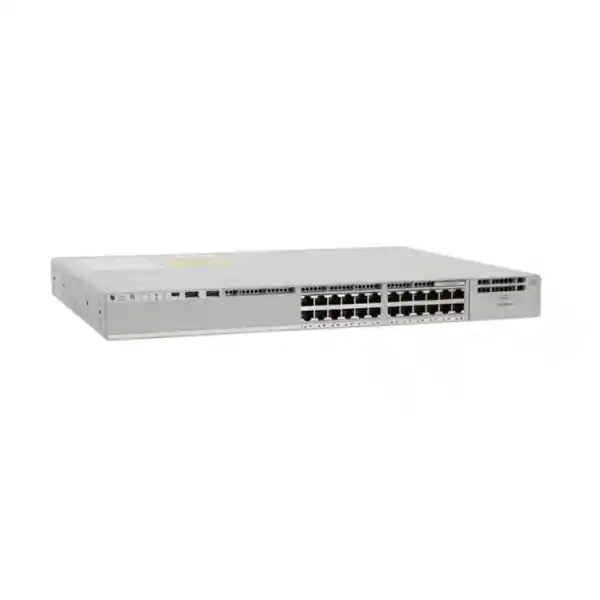
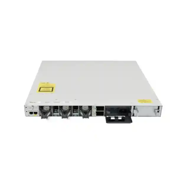
Cisco Catalyst C9300-24P Network Switch for UAE Enterprise Access Networks
The Cisco Catalyst C9300-24P is a 1RU stackable campus access switch built around Cisco’s UADP 2.0 architecture. It combines twenty-four 10/100/1000 Mbps copper access interfaces with IEEE PoE+ power delivery, field-selectable modular uplinks, high-speed StackWise-480 stacking, redundant power options, Cisco IOS XE programmability, and the policy, telemetry, segmentation, and resiliency features expected in modern enterprise networks. For organizations in Dubai and across the United Arab Emirates, the platform is especially relevant where one access layer must simultaneously support user endpoints, IP phones, Wi-Fi access points, cameras, badge readers, meeting-room devices, IoT endpoints, and routed campus services without turning every wiring closet into a collection of independent unmanaged systems.
Direct answer: when is the C9300-24P the right switch?
Choose the C9300-24P when you need a premium Cisco enterprise access switch with twenty-four one-gigabit copper ports, up to 30W-class PoE+ endpoint capability per supported port, modular rather than fixed uplinks, hardware stacking, and a software platform suitable for standardized campus operations. The model is well matched to a floor, department, branch, secure office, training facility, retail back office, healthcare zone, hospitality administration area, or smaller distribution-access block where 24 powered endpoints is an appropriate port density and where the design team values uplink choice and stack resiliency more than the lowest initial switch cost.
It is not automatically the right choice for every new wireless project. If the access design requires multigigabit edge speeds for high-throughput Wi-Fi 6E or Wi-Fi 7 access points, or requires 60W/90W power classes at large scale, a multigigabit or UPOE/UPOE+ Catalyst 9300 variant may be more appropriate. The C9300-24P is strongest when the cabling plant and endpoint requirement remain primarily 1 Gigabit Ethernet and PoE+, while the uplink and stacking architecture must still provide enterprise-grade growth.
Twenty-four 10/100/1000 Mbps copper ports for powered and non-powered access devices. This suits standard Cat5e/Cat6 horizontal cabling and established Gigabit Ethernet access designs.
With the current default 715W AC power-supply configuration, approximately 445W is available for PoE. Full 30W allocation across all 24 access ports requires a higher or combined power configuration.
Standalone switching capacity is 208 Gbps with a forwarding rate of 154.76 Mpps. With stacking, platform figures rise to 688 Gbps switching capacity and 511.90 Mpps forwarding.
Dedicated hardware stacking provides a 480 Gbps stack architecture and supports up to eight compatible C9300-class members under the relevant Cisco stacking and licensing rules.
Catalyst 9300 modular-uplink models provide 8 GB DRAM and 16 GB flash, supporting the IOS XE operating environment, telemetry, automation, and platform services.
The chassis is approximately 1.73 × 17.5 × 16.1 inches without the installed supply depth; with the default supply it extends to roughly 17.7 inches deep.
Hardware architecture: why UADP 2.0 matters
The C9300-24P is based on one Cisco UADP 2.0 ASIC. UADP, or Unified Access Data Plane, is central to the Catalyst 9000 design because it gives Cisco a programmable forwarding architecture rather than treating switching features as unrelated fixed blocks. In practical network engineering terms, the ASIC handles the high-speed data plane while IOS XE programs policy, forwarding, quality-of-service, security, visibility, and service behavior. The result is an access switch that can implement a substantial set of enterprise functions in hardware instead of forcing traffic into a software-only path for routine campus features.
For the C9300-24P class, this architecture supports 32,000 MAC addresses, up to 32,000 IPv4 route entries in the relevant platform scale profile, 16,000 IPv6 routing entries, 8,000 multicast routes, 5,120 QoS scale entries, 5,120 ACL scale entries, a 16 MB packet buffer for Gigabit Ethernet models, and up to 64,000 Flexible NetFlow entries. It also supports 4094 VLAN IDs, up to 1000 switched virtual interfaces, and jumbo frames up to 9198 bytes. These numbers are not simply marketing capacity statements. They help architects determine whether the access layer can sustain the policy scale, segmentation model, routed-access design, endpoint population, and telemetry load planned for the site.
The configurable allocation concept is important. Enterprise networks rarely need the maximum possible count of every table simultaneously. A financial office may need more security-policy entries; a large routed-access environment may need more IP forwarding scale; an IoT deployment may have high endpoint diversity; a traditional office floor may stay well below all platform limits. Cisco’s programmable pipeline and template approach allows the switching platform to be tuned around these demands. This is one reason the C9300-24P is best evaluated as a system component rather than as a commodity 24-port PoE switch.
PoE+ engineering: calculate the real load before you quote
Power over Ethernet is often where an apparently simple 24-port bill of materials becomes incorrect. The C9300-24P can deliver PoE+ on its access interfaces, but the total power available to attached devices is governed by the installed power supplies and the switch’s internal power requirements. With the current 715W AC supply configuration, the available PoE budget is approximately 445W. That is enough for many real-world mixed endpoint environments, but it is not enough to reserve 30W on all 24 ports simultaneously. Twenty-four endpoints at 30W represent 720W of endpoint allocation before considering how the system power architecture is built.
A correct sizing exercise therefore starts with endpoint classes and actual maximum draw. A typical IP phone may use substantially less than 30W. A badge reader, small camera, or IoT gateway may require only single-digit watts. A pan-tilt-zoom camera, video endpoint, or certain wireless access points can consume much more. Engineers should build a port-by-port budget including planned devices, likely peak draw, spare ports, and a growth reserve. If the calculation approaches the available budget, choose a stronger or redundant power-supply combination instead of hoping that average consumption will remain low.
Example A: voice-heavy office
Assume 18 IP phones at 8W, four cameras at 12W, and two small wireless access points at 18W. Estimated powered load is 228W. Adding a meaningful design reserve still fits comfortably inside a 445W default PoE budget.
Example B: power-dense edge
Assume 12 devices at 25W and 12 devices at 20W. The calculated endpoint requirement is 540W before a reserve. The default supply is no longer an appropriate assumption, so the quotation should include the required higher or additional PSU design.
For full PoE+ on all twenty-four ports, Cisco’s power guidance calls for a 1100W-class primary supply or a dual-715W configuration, depending on the selected power-supply generation and ordering option. This is also where redundancy objectives matter. A design may have enough total power with two supplies but still lose PoE headroom after one supply fails. Critical voice, security, healthcare, or building systems should be sized for the required failure state, not only normal operation.
StackPower can add another layer to the power design by allowing compatible stacked switches to share power resources. That can simplify resiliency planning in selected architectures, yet it should still be engineered from actual switch and PoE loads. Treat StackPower as an architectural capability, not as a substitute for calculating watts, failure scenarios, and UPS runtime.
Modular uplinks: one chassis, multiple aggregation strategies
Unlike fixed-uplink access switches, the C9300-24P uses a field-replaceable network-module bay. The switch does not require the enterprise to commit permanently to one uplink format at the original purchase. This is a meaningful advantage when a building is being migrated from legacy 1G aggregation to 10G, 25G, or 40G campus links, or when a standard switch model must be deployed across sites with different distribution-layer capabilities.
Current modular choices for the Catalyst 9300 family include the C9300-NM-4G with four 1 Gigabit SFP interfaces; C9300-NM-8X with eight 10G/1G SFP+ interfaces; C9300-NM-2Q with two 40 Gigabit QSFP interfaces; C9300-NM-2Y with two 25G/10G/1G SFP28 interfaces; and C9300-NM-4M with four multigigabit copper uplinks. The practical selection depends on media type, optic standards, link redundancy, distribution-switch capabilities, distance, fiber type, port-channel strategy, and expected east-west and north-south utilization.
A 24-port 1G access layer theoretically exposes up to 24 Gbps of full-duplex edge demand before considering stacking traffic and local switching. Real office traffic is bursty and oversubscription is normal, so the uplink is not chosen simply by adding access-port line rates. A pair of 10G uplinks is common because it provides substantial aggregate capacity and path diversity. However, sites with heavy local backup, media production, dense wireless, high-volume surveillance, virtualization endpoints, or a routed-access design may justify 25G or 40G uplinks. Conversely, a low-utilization branch with a 1G WAN and modest local services could be adequately served by 1G fiber uplinks.
The uplink module is therefore part of the architecture, not an accessory selected at the last minute. FourTeck can align the module, optic type, fiber patching, and aggregation interface with the existing core or distribution layer. For broader UAE infrastructure planning, customers can also review enterprise networking coverage at FourTeck UAE.
StackWise-480: designing the access stack as one operational system
The C9300-24P supports Cisco StackWise-480, providing 480 Gbps of stack bandwidth. Up to eight compatible Catalyst 9300 members can operate in a stack under Cisco’s supported model and license-level rules. The purpose of stacking is not merely to increase port count. A well-designed stack creates a shared management and control construct that can simplify configuration, uplink distribution, gateway placement, software operations, and failure recovery across multiple physical switches.
In a typical floor design, two to four access switches are stacked in the same telecommunications room. Uplink links can be distributed across different stack members and bundled toward redundant distribution switches. If one member fails, endpoints connected directly to that member go offline, but the stack can continue operating through surviving members. If an uplink or power supply fails, properly designed alternate paths remain available. The stack therefore becomes an important tool for reducing the blast radius of individual component failures while preserving operational simplicity.
Stack cable placement matters. A ring topology is normally preferred so that the stack has redundant data paths. Cable lengths should be selected based on rack layout rather than using excessive cable slack that obstructs airflow and maintenance. Engineers must also keep software compatibility, member provisioning, priority, version control, and change procedures in the implementation plan. Stacking eliminates many management burdens, but it does not eliminate the need for disciplined lifecycle management.
The published C9300-24P bandwidth figures illustrate the distinction between standalone and stacked operation: 208 Gbps switching capacity and 154.76 Mpps forwarding rate in standalone terms, with 688 Gbps switching capacity and 511.90 Mpps forwarding when stacking is included in Cisco’s platform figures. These values are useful when comparing Catalyst models, but real application performance depends on traffic patterns, uplink design, policy features, buffering requirements, and the physical topology.
For large campuses, a stack should be sized around more than the maximum eight-member count. Consider failure domains, closet UPS capacity, cable management, rack space, PoE load, maintenance windows, uplink diversity, and the operational effect of a stack-wide software change. Sometimes two smaller stacks provide better fault isolation than one very large stack even when both designs fit the technical maximum.
Layer 2 access: segmentation, loop control, endpoint admission, and clean fault domains
At the campus edge, the basic job of a switch is still to connect endpoints reliably, but enterprise Layer 2 design now involves far more than assigning an access VLAN. The C9300-24P supports thousands of VLAN identifiers, large spanning-tree scale, link aggregation, voice and data segmentation, security controls, and policy mechanisms that help a network team enforce predictable endpoint behavior.
A recommended access design begins with intentional VLAN boundaries. User data, voice, cameras, access control, printers, guest services, building management, and network-management traffic should be separated according to risk and operational requirements rather than mixed into one broad broadcast domain. The exact segmentation strategy may use traditional VLANs and VRFs, or it may participate in a wider software-defined access architecture. In either case, consistent interface templates reduce mistakes and make onboarding predictable.
Spanning Tree remains relevant wherever Layer 2 loops are possible. Edge ports should be treated as edge ports and protected accordingly; uplinks and inter-switch relationships should be explicitly designed. Features such as BPDU Guard, Root Guard, loop-protection techniques, EtherChannel, storm control, DHCP snooping, Dynamic ARP Inspection, and IP Source Guard can become part of the access template where appropriate. Their exact availability and licensing should be validated against the chosen IOS XE release and license package during the solution design.
The C9300 platform’s 300 PVST instance scale, 13,000 STP virtual-port scale, 1000 SVI scale, and 9198-byte jumbo-frame support provide substantial room for enterprise campus use. These limits should still be understood in context: an organization does not benefit from creating hundreds of VLANs merely because the switch can hold them. Good design minimizes unnecessary Layer 2 extension, uses routing boundaries intentionally, and documents ownership of every segment.
For migrations from older Catalyst 2960, 3560, 3750, 3850, or mixed-vendor access networks, the C9300-24P can be introduced using familiar VLAN and trunking concepts first, then progressively integrated with advanced automation and policy. This staged method is often safer for active UAE offices where a migration must fit into a limited evening or weekend maintenance window.
Layer 3 and routed access: more than an edge-only switch
The Catalyst 9300 family can participate in routed campus designs, allowing the access layer to terminate Layer 3 boundaries instead of extending every VLAN toward a centralized distribution layer. The C9300 modular-uplink platform provides substantial route, SVI, ACL, and forwarding scale for this role. Whether routed access is appropriate depends on organizational standards, license level, convergence requirements, segmentation architecture, and the competence of the operating team.
The platform scale for standard Catalyst 9300 modular-uplink models includes up to 32,000 IPv4 routes in the relevant table profile, 16,000 IPv6 route entries, 8,000 multicast routes, and up to 448 routed ports per compatible Catalyst 9300 stack. Network architects should avoid reading these as guaranteed application numbers under every feature combination. Hardware table resources, software release, SD-Access requirements, QoS, ACL usage, and feature templates can influence the practical scale. The important point is that the C9300-24P has an architecture intended to support serious enterprise routing, not only simple static management addressing.
A routed-access design can reduce Layer 2 failure domains and improve convergence by using point-to-point routed links from the access stack toward distribution. Dynamic routing provides deterministic path selection and can simplify multi-building campuses. Traditional designs may instead keep default gateways at distribution and use trunked VLANs. Both approaches are valid when implemented well. The selection should follow business availability requirements, operational maturity, and compatibility with existing network services rather than fashion.
License selection is important here because routing and advanced policy features are divided across Cisco’s Network Essentials and Network Advantage base tiers. The precise feature-to-license mapping should be checked for the target IOS XE release before purchase. If the project expects advanced routing, software-defined segmentation, or specific automation functions, build those requirements into the BOM at quotation time so the installed switch does not arrive with an insufficient software entitlement.
Security architecture at the access edge
The access switch is one of the first enforcement points an endpoint encounters. That makes the C9300-24P relevant to network security even though it is not a firewall. The switch can participate in identity-aware admission, role-based segmentation, access control, source validation, first-hop security, encrypted management, telemetry, and network detection workflows. The architecture is particularly useful where users, phones, cameras, contractors, IoT devices, and operational technology share the same physical cabling environment but must not share the same trust level.
802.1X and MAC Authentication Bypass are common access-control methods in enterprise environments. A managed workstation can authenticate using 802.1X, while a device without a supplicant, such as a legacy printer or specialized IoT unit, may be handled through a controlled alternative method. Centralized policy systems can then return VLAN, downloadable ACL, or role information depending on the organization’s architecture. The switch becomes the enforcement point that converts identity decisions into actual forwarding policy.
Local edge protections are equally important. DHCP snooping can help establish trusted binding information; Dynamic ARP Inspection can use that information to block selected spoofing attempts; IP Source Guard can limit unauthorized source addressing; port-security policies can constrain unexpected endpoint changes; storm control can prevent certain traffic floods from consuming a segment; and control-plane policing protects the switch CPU from inappropriate traffic patterns. These controls must be deployed carefully because a technically correct security feature can still create an outage if trust boundaries and special devices are not documented.
For organizations using Cisco’s software-defined campus approach, Catalyst 9300 platforms can form part of an SD-Access fabric where policy and segmentation are centrally defined. That can reduce dependence on manually maintaining large sets of VLANs and ACLs across every closet. The value depends on broader infrastructure such as identity services, Catalyst Center, routing underlay, and trained operations. A standalone C9300-24P remains fully useful without deploying the entire architecture.
Perimeter and inter-zone firewall policy remains a separate design concern. FourTeck’s firewall and segmentation practice can be reviewed at Firewall Dubai when the switch project is part of a broader secure campus refresh.
QoS for voice, video, collaboration, and critical applications
A PoE switch often carries IP telephony and collaboration traffic, which makes Quality of Service an operational requirement rather than an optional optimization. The C9300 architecture provides extensive QoS resources and programmable classification and queuing capabilities. The objective is not to give voice absolute priority over everything; it is to define trust boundaries, classify traffic consistently, police or shape where required, and ensure congestion is handled according to business intent.
At an IP phone port, the design may use a dedicated voice VLAN while a workstation connects through the phone’s internal switch. The access policy can recognize or remark traffic based on trusted device relationships and organizational standards. Real-time media should receive low-latency treatment across the full path, not only at the access interface. If the WAN, wireless network, firewall, or distribution layer discards or re-marks those packets incorrectly, a perfect access-switch QoS policy will not preserve call quality.
Video conferencing adds a second challenge because bandwidth per session is much higher than traditional narrowband voice. Modern meeting rooms can generate multiple high-definition streams, content sharing, cloud recording traffic, and management sessions. A 24-port access switch can therefore host a small number of devices that collectively produce substantial bursts. This reinforces the need to select uplink bandwidth from application behavior rather than endpoint count alone.
QoS scale on the standard Catalyst 9300 modular-uplink family is published at 5,120 entries. Most ordinary access deployments will stay far below this number, but policy-heavy environments should document how ACL and QoS resources interact with the selected hardware templates. Engineers should test complex policies in a representative configuration before a large rollout, especially when migrating rules from an older Catalyst generation whose hardware resource model differs.
Wireless access: where the C9300-24P fits and where it does not
The C9300-24P can power and connect enterprise wireless access points that operate within the capabilities of 1 Gigabit Ethernet and PoE+. For many offices, guest zones, retail areas, warehouses, and legacy wireless refreshes, that remains perfectly practical. However, the radio capability of modern access points can exceed a single 1G wired interface, and some models require higher PoE classes. The switch should therefore be selected after the access-point model is known, not before.
If the wireless design uses access points with multigigabit Ethernet, connecting them to 1G ports creates a wired bottleneck even though the AP may still function. If the AP needs more than PoE+ power under the intended radio configuration, it may operate in a reduced mode or require an alternative power method. In those cases, a C9300-24U, C9300-24UX, C9300-24H, or another suitable UPOE/multigigabit variant can be the better engineering choice. The C9300-24P should not be positioned as a universal wireless switch simply because it belongs to the Catalyst 9300 family.
For existing 802.11ac or moderate-density Wi-Fi 6 deployments whose wired edge is intentionally 1G and whose AP power draw fits PoE+, the model can still be an excellent fit. The modular uplink can provide 10G or faster aggregate connectivity toward distribution, while the stack architecture delivers resiliency and centralized operation across multiple access switches.
A good wireless-ready quotation lists AP model, maximum negotiated Ethernet rate, PoE class, number of radios, expected SSID and client density, uplink oversubscription target, and whether the access layer must support future AP upgrades. This avoids a common procurement mistake: buying a switch with enough physical ports but insufficient speed or power for the devices that will actually connect to them.
Flexible NetFlow, telemetry, automation, and operational visibility
The operational value of a modern enterprise switch is heavily influenced by how well it can explain what is happening on the network. The Catalyst 9300 platform supports Flexible NetFlow scale, model-driven programmability, telemetry, APIs, and Cisco IOS XE automation features that can feed network management and analytics platforms. The C9300-24P standard modular-uplink family supports up to 64,000 Flexible NetFlow entries in the relevant platform scale, giving operations teams a strong basis for traffic visibility when properly configured.
Traditional SNMP polling remains useful for interface counters, device health, inventory, and alarms, but streaming telemetry can provide more timely state information without relying exclusively on periodic polling. Model-driven interfaces allow network tools to interact with structured data rather than screen-scraping command output. This is valuable in environments where dozens or hundreds of switches must be operated consistently and where manual CLI-only administration no longer scales.
Cisco IOS XE also supports automation frameworks that can standardize deployment. A team can define switch templates, VLAN assignments, authentication policy, QoS, management access, syslog, NTP, AAA, routing, and monitoring as repeatable configuration building blocks. Automation does not eliminate the need for network expertise. It makes expertise reusable and reduces the number of one-off commands typed differently in each closet.
For troubleshooting, flow visibility and telemetry help answer practical questions: Which endpoints are generating the most traffic? Is one application saturating the uplink? Did an endpoint move ports? Are error counters increasing? Is packet loss correlated with a link or policy change? Is a camera VLAN generating unexpected internet traffic? Is a branch switch operating near CPU or memory thresholds? These questions become faster to answer when observability is designed into the rollout from day one.
Customers requiring configuration, monitoring, migration, or managed infrastructure assistance can align the switch deployment with FourTeck IT Services UAE so that hardware procurement and operational implementation are planned together.
Licensing: Network Essentials, Network Advantage, and Cisco software subscriptions
Catalyst 9300 licensing should be treated as part of the technical specification. Cisco offers the C9300-24P with different base license levels, including Network Essentials and Network Advantage, represented in common ordering as C9300-24P-E and C9300-24P-A. The base network license is perpetual and tied to the hardware. Cisco also uses term-based Catalyst/DNA software subscriptions in 3-, 5-, or 7-year terms for the traditional Catalyst licensing model, with available package names and purchasing rules evolving over the platform lifecycle.
Network Essentials is oriented toward core switching and selected routing, management, and automation capabilities. Network Advantage adds more advanced functions. The exact feature mapping must be checked against the Cisco feature matrix for the target IOS XE release because broad statements such as “Advantage has more routing” are not sufficient for procurement. Requirements should be written feature by feature: routing protocol, VRF scale, policy, segmentation, telemetry, SD-Access role, automation, encrypted traffic analytics, or any other function expected in production.
Smart Licensing Using Policy is relevant to modern Catalyst 9000 operations. The objective is license compliance and reporting without making basic network operation dependent on a fragile registration workflow. Teams still need an asset and entitlement process so serial numbers, contracts, software subscriptions, and renewal dates are documented. License management should be included in handover documentation rather than left with a procurement mailbox after installation.
Cisco now also offers Catalyst 9300 variants orderable for Meraki cloud-management mode using “-M” part numbers. That does not mean a standard C9300-24P-E or -A should be quoted as a Meraki-managed unit without confirming the exact SKU, subscription, management mode, migration path, and customer requirement. For a conventional IOS XE enterprise design, the -E or -A selection remains the key base-license decision.
When requesting pricing, provide the intended license tier, subscription term, support requirement, uplink module, optics, stacking cables, secondary PSU requirement, and any storage or accessories. That allows the quotation to represent a deployable solution rather than a bare chassis that requires additional purchases before it can meet the design.
Power redundancy, fans, rack depth, and environmental planning
The C9300 family supports dual redundant power supplies. A switch ships with one supply in the normal configuration, and a second supply can be ordered initially or added later. The power bays support operational designs where a single PSU failure does not immediately take down the switch, but engineers should also calculate whether the remaining supply can sustain the required PoE load after a failure. Redundant electronics without sufficient surviving wattage is incomplete redundancy.
The platform uses three field-replaceable fan modules and supports N+1 fan redundancy. This is valuable in enterprise closets because a fan failure can be serviced without replacing the entire switch. Airflow clearance remains essential. Do not obstruct the inlet or exhaust with tightly bundled patch cords, unused packing material, poorly placed vertical PDUs, or deep passive equipment immediately behind the chassis.
The C9300-24P chassis is approximately 1.73 inches high and 17.5 inches wide. Chassis depth is roughly 16.1 inches, extending to approximately 17.7 inches with the default power supply and around 19.2 inches with a 1100W-class supply. Rack designers should add room for cable bend radius and rear service access; a nominal 18-inch cabinet is not automatically suitable merely because the metal chassis measurement appears close. Deep power supplies and fiber patching can make rear clearance the actual constraint.
Cisco specifies normal operating temperature ranges that vary with altitude, including operation up to 45°C at lower elevations under normal conditions, with specified short-term exceptional limits under controlled constraints. UAE network rooms should never rely on upper device thermal limits as a substitute for air conditioning. Local ambient temperature, humidity, dust, door opening, UPS heat output, and building HVAC failure modes should be included in the site survey. A network closet that reaches extreme heat every summer is an availability problem even if the switch can temporarily tolerate the temperature.
For critical sites, connect redundant PSUs to independent PDUs or UPS-backed power paths where the facility design supports it. Feeding both supplies from one power strip creates component redundancy but not source redundancy. Document circuit identifiers, UPS runtime assumptions, load percentage, and shutdown policy as part of commissioning.
Performance and scale reference for the C9300-24P class
Scale values are platform references, not a promise that every maximum can be used simultaneously under every feature combination. Final design should use the selected IOS XE release, license, SDM template, policy profile, and Cisco feature guidance.
Deployment topology 1: resilient office-floor access
A common deployment places two C9300-24P switches in one floor telecommunications room and forms them into a StackWise ring. Users, phones, cameras, printers, and access points are distributed across both members. Two or more uplink interfaces are then split across different physical stack members and connected to redundant distribution switches using port-channel or routed links according to the campus design. A second PSU is installed in each access switch where the availability target justifies it.
This topology provides forty-eight access ports while retaining the operational simplicity of one stack. A single member failure removes the local ports on that chassis but the surviving member and its uplinks remain available. A single uplink failure can be absorbed by the port-channel or routing design. A single PSU failure can be tolerated when the second PSU and PoE capacity are correctly sized. The result is not zero downtime for every endpoint, but it removes several avoidable single points of failure.
For executive areas or critical meeting zones, endpoints can be intentionally spread across stack members so one hardware failure does not disconnect every room in the same department. The same principle can be applied to wireless coverage by distributing adjacent access points across different switch members where cabling paths permit.
Deployment topology 2: branch office with local routing and centralized security
In a branch, the C9300-24P can aggregate office endpoints into user, voice, camera, guest, and management segments. The switch may provide local inter-VLAN routing where policy permits, while traffic destined for the internet, data center, SaaS security service, or headquarters is forwarded toward a branch firewall or SD-WAN edge. The branch can use two fiber uplinks to that edge or to a small redundant aggregation layer depending on physical layout.
The benefit of using a Catalyst 9300 in a branch is consistency with the central enterprise. Configuration templates, AAA, logging, monitoring, network access control, software standards, and automation can remain aligned across headquarters and remote offices. This reduces the support burden created by deploying a different low-cost switch family at every branch.
The tradeoff is cost and complexity. A five-user branch with six endpoints may not justify a C9300-24P. A 40-user regulated office with voice, cameras, secure access control, redundant WAN, and strict monitoring may justify it easily. Sizing should reflect operational value, not only port count.
Deployment topology 3: IP surveillance and building systems
PoE switches are frequently used for cameras, access-control readers, intercoms, environmental sensors, lighting controllers, and other building systems. The C9300-24P is suitable when those endpoints fit Gigabit Ethernet and PoE+ power requirements. Enterprise switching features provide a stronger operational foundation than unmanaged camera switches because the security team can segment devices, monitor traffic, authenticate management access, and integrate switch events with central monitoring.
Camera networks require special attention to bandwidth because surveillance traffic is sustained rather than purely bursty. Twenty cameras each averaging 8 Mbps represent about 160 Mbps of continuous video before peaks, management, multicast, backups, or additional devices. Higher-resolution cameras at higher frame rates can increase this substantially. The uplink should be sized from actual codec and recording parameters, and the NVR path should avoid unnecessary congestion points.
Power calculation is equally important. Outdoor cameras, PTZ units, heaters, IR illumination, and specialized sensors can draw much more than simple fixed indoor cameras. The quotation should use maximum or design draw rather than marketing-average consumption. If all 24 ports are intended for power-dense surveillance devices, the default 445W budget may not be sufficient.
C9300-24P vs nearby Catalyst 9300 choices
| Model family | Edge type | Power class | Best fit |
|---|---|---|---|
| C9300-24P | 24 × 1G copper | PoE+ up to 30W-class endpoint support | Standard enterprise powered access with modular uplinks |
| C9300-24T | 24 × 1G copper | Data only | Desktops, servers, printers, or environments not requiring PoE |
| C9300-24U | 24 × 1G copper | Higher UPOE power | Devices requiring more power than standard PoE+ |
| C9300-24UX | Multigigabit copper | UPOE | High-throughput wireless APs and multigigabit edge devices |
| C9300-24H | 24 × 1G copper | UPOE+ / 90W class | High-power smart-building and advanced endpoint requirements |
| C9300L-24P variants | 24 × 1G copper | PoE+ | Projects preferring fixed uplinks and a different stacking architecture |
The key selection questions are therefore edge speed, endpoint power, uplink modularity, stacking standard, software feature level, and lifecycle compatibility with the installed campus. The C9300-24P is often the balanced choice for mature Gigabit Ethernet access environments, but it should not be chosen when a different model clearly matches the endpoint requirement better.
Sizing methodology for UAE projects
A repeatable sizing method prevents overbuying and avoids underpowered access closets. Start with physical port count. Count every planned endpoint, then add ports for growth and for operational flexibility. A closet with 23 known devices is not a comfortable fit for a 24-port switch if two additional cameras are planned next quarter. Where rack space and budget permit, maintain spare capacity or deploy an additional stack member before the closet is completely full.
Second, classify each endpoint by speed. If all endpoints are 100M or 1G and are expected to remain so for the design life, the C9300-24P fits well. If several access points, engineering workstations, imaging systems, or production devices need 2.5G, 5G, or 10G copper, move to a multigigabit model rather than accepting avoidable bottlenecks.
Third, build the PoE spreadsheet. List device type, quantity, negotiated PoE class, vendor maximum draw, design draw, and redundancy requirement. Add a growth reserve. Compare the result with the PoE available under normal operation and under one-PSU-failed operation if resilience is required. This one step prevents a large percentage of real-world PoE problems.
Fourth, estimate traffic. Use camera bit rates, AP traffic expectations, voice and video concurrency, server transfers, backup windows, cloud usage, and branch WAN characteristics. Decide whether 1G, 10G, 25G, or 40G uplinks are appropriate and whether two or more links should be bundled or routed independently. Select the network module only after this calculation.
Fifth, define resiliency. Decide how many stack members can fail, whether a PSU failure must be transparent, whether uplinks terminate on separate distribution devices, whether the closet has dual power circuits, how much UPS runtime is required, and whether a maintenance event can take down the whole stack. Resiliency is a business requirement translated into topology, not a checkbox on the switch data sheet.
Sixth, select software. Document every feature that matters and map it to Network Essentials or Network Advantage plus the appropriate subscription. Avoid choosing licensing solely on price. A lower license that cannot support the target routing or segmentation feature is not a saving; it is a delayed change order.
Finally, capture site constraints: rack depth, patch-panel location, optic type, fiber connectors, ambient temperature, PDU outlet type, UPS capacity, grounding, patch-cord lengths, labeling standards, and change window. UAE deployments frequently combine equipment from several generations in the same communications room, so physical compatibility is just as important as logical configuration.
Migration from older Catalyst access switches
Replacing an older access switch is not simply a copy-and-paste exercise. A configuration written for Catalyst 2960, 3560, 3750, 3850, or an older IOS release may contain commands, defaults, QoS constructs, authentication behavior, spanning-tree assumptions, or interface naming that differ on IOS XE and Catalyst 9300. The safest migration converts the legacy configuration into an intended-state template rather than treating every historical line as a requirement.
Begin by auditing actual port use. Identify connected MAC addresses, VLANs, descriptions, voice devices, trunks, port channels, disabled ports, PoE consumption, errors, and special security policy. Old closets often contain abandoned interfaces and undocumented exceptions. Migrating only required configuration produces a cleaner target state and reduces troubleshooting after cutover.
Validate optics and uplink media before the change window. An existing SFP or SFP+ may have compatibility, distance, fiber, connector, or support considerations. Verify the selected C9300 network module and optic combination against the distribution device. Clean fiber connectors and test links where practical. Many “switch migration” outages are actually patching or optics problems discovered after the old switch has already been removed.
Pre-stage software, licensing state, stack membership, hostname, management address, AAA, NTP, DNS, logging, SNMP or telemetry, VLAN database, routing, and standard access templates. Save a validated startup configuration and maintain rollback documentation. Label stack cables, power cords, uplinks, and access bundles before disconnecting the old equipment.
During cutover, move uplinks first according to the documented sequence, verify control-plane stability, then migrate endpoint groups. Confirm PoE delivery, authentication, DHCP, voice registration, camera recording, wireless AP joins, routing, internet access, monitoring, and logging. A successful “ping to gateway” is not a complete acceptance test.
After migration, compare port counters and endpoint inventory to the pre-change baseline. Look for speed or duplex anomalies, CRC errors, unexpected STP state, excessive PoE draw, missing phones, unjoined APs, inactive cameras, or policy authentication failures. Archive the final running configuration and update the asset inventory immediately while the change information is still accurate.
UAE procurement considerations: quote the complete deployable switch
Enterprise switch pricing can look inconsistent when two quotations use the same chassis name but include different software, support, uplink modules, optics, power supplies, stacking accessories, or subscription terms. For the Cisco Catalyst C9300-24P, the procurement specification should define the complete bill of materials. The chassis alone does not tell the buyer whether the solution includes Network Essentials or Network Advantage, which uplink module is installed, whether a second PSU is present, whether stacking cables are included, or whether required optics are part of the quote.
For UAE projects, also verify delivery location, rack environment, plug and PDU compatibility, required documentation, warranty/support route, installation scope, configuration scope, and whether commissioning occurs during normal hours or a controlled maintenance window. If the switch is being exported onward to another country or deployed into a multinational standard, confirm region-specific support and commercial terms rather than assuming the UAE quotation transfers unchanged.
Serial-number traceability is important for enterprise lifecycle management. Record switch serials, PSU serials where relevant, license entitlements, support contracts, optic part numbers, stack-cable identifiers, and installation location. Good asset data becomes valuable during RMA, audit, renewal, software planning, and incident response.
A complete quotation should also distinguish hardware supply from implementation services. Some customers need only equipment delivery. Others require rack installation, stacking, software alignment, migration, AAA integration, VLAN and routing configuration, firewall changes, wireless coordination, testing, documentation, and post-change support. Defining this boundary prevents assumptions on both sides.
Organizations coordinating regional network standards beyond the UAE can use FourTeck Global as a reference point for broader enterprise infrastructure engagement.
Configuration design checklist
Management plane
Define management VRF or VLAN, SSH, AAA, TACACS+/RADIUS, local fallback, NTP, DNS, SNMP or telemetry, syslog, configuration archive, role-based access, login banners, and out-of-band strategy.
Layer 2 policy
Standardize access VLAN, voice VLAN, trunk policy, native VLAN handling, allowed VLANs, STP edge settings, BPDU protections, storm control, EtherChannel, unused-port shutdown, and interface descriptions.
Access security
Plan 802.1X, MAB exceptions, DHCP snooping, ARP inspection, source guard, port security where applicable, downloadable policy, device profiling, management ACLs, and trusted uplink boundaries.
Routing
Define default-gateway placement, routed uplinks, dynamic routing, passive interfaces, route filtering, first-hop redundancy where used, VRFs, multicast, IPv6, and summarization strategy.
PoE and hardware
Record per-port power requirements, PSU inventory, stack cables, StackPower design if used, uplink module, optic types, spare transceivers, fan status, rack unit, patching, and UPS circuits.
Acceptance testing
Verify endpoint DHCP, DNS, voice, wireless, cameras, authentication, internet path, internal applications, failover, monitoring, syslog, time synchronization, config backup, stack state, PoE budget, and environmental alarms.
Operational lifecycle: software, backups, monitoring, and change control
A Catalyst switch should enter production with a lifecycle plan. Select an IOS XE release based on Cisco support guidance, feature requirements, known defects, and interoperability rather than simply installing the newest available image on the day of deployment. Standardize releases across a stack and ideally across similar campus blocks so troubleshooting and automation are predictable.
Configuration backups should be automated. Maintain both the intended template and periodic device backups. A backup that has never been tested for restore is only a file, not a recovery process. Record software images, boot variables, license state, stack membership, and critical external dependencies such as AAA and NTP servers.
Monitoring should cover interface state, error counters, bandwidth, packet discards, PoE allocation, temperature, fan and PSU status, CPU, memory, stack status, route adjacency, STP changes, authentication failures, and environmental alarms. Alert thresholds should reflect the site. A camera access switch may carry sustained traffic all day, while an office-floor switch may show strong peaks around meeting and backup periods.
Change control is especially important for stacks because one software action can affect many endpoints. Document upgrade method, compatibility, expected reload behavior, stack-member readiness, rollback plan, business owner, validation steps, and maintenance window. Where high availability is required, design the topology and operational process so a single maintenance event does not unnecessarily remove every user path.
Periodic review should also check license renewals, support coverage, spare inventory, optic health, UPS batteries, room cooling, unused ports, stale VLANs, authentication exceptions, and configuration drift. The physical switch can remain serviceable for years, but the network around it continuously changes. Lifecycle discipline preserves the value of the original hardware investment.
Frequently asked technical questions
Does the C9300-24P have 24 PoE+ ports?
Yes. It provides twenty-four 10/100/1000 Mbps copper access ports with PoE+ capability. The total simultaneously deliverable PoE is constrained by the installed PSU combination, so port capability and total power budget must be considered separately.
Can it provide 30W to all 24 ports with the default PSU?
No. The current default 715W supply provides roughly 445W of available PoE, while 24 × 30W equals 720W. A higher or combined power configuration is required when the design truly needs full PoE+ allocation across every port.
Are the uplinks fixed?
No. The C9300-24P uses an optional modular uplink bay. Available Catalyst 9300 modules include 1G SFP, 10G/1G SFP+, 25G/10G/1G SFP28, 40G QSFP, and multigigabit copper options, subject to Cisco module compatibility rules.
How many switches can be stacked?
Catalyst 9300 StackWise-480 designs support up to eight compatible members under the applicable model and license-level rules. The optimal production stack may be smaller depending on fault-domain, maintenance, power, and closet constraints.
Is it suitable for Wi-Fi 6 or Wi-Fi 7?
It can support APs whose Ethernet and PoE requirements fit 1G and PoE+. For APs that require multigigabit wired throughput or higher power classes, choose a suitable multigigabit/UPOE Catalyst model instead of accepting a bottleneck or reduced AP feature mode.
Does it support redundant power?
Yes. The Catalyst 9300 modular-uplink family supports two power-supply bays. The second supply can provide hardware redundancy and additional PoE capacity, but the design should verify available power after a single-PSU failure.
What is its switching capacity?
Cisco publishes 208 Gbps standalone switching capacity and 154.76 Mpps forwarding for the C9300-24P, with 688 Gbps switching capacity and 511.90 Mpps forwarding figures when stacking is included.
Which license should be purchased?
Choose the license by required features. Network Essentials and Network Advantage are the primary perpetual base tiers, with term software subscriptions added according to Cisco ordering policy. Validate exact feature mapping for the target release before purchasing.
What a FourTeck technical quote should define
A useful quotation for the Cisco Catalyst C9300-24P should remove ambiguity. It should state the exact base SKU and license level, software subscription term, power-supply configuration, uplink module, optic or DAC requirements, stacking cable lengths, StackPower accessories if used, rack accessories, support coverage, delivery scope, configuration scope, installation scope, migration scope, and documentation deliverables. It should also note any dependencies that remain customer-provided, such as fiber patching, rack PDU outlets, UPS capacity, addressing, AAA servers, firewall policy, or change approvals.
When the switch is part of a larger refresh, the quote should identify whether access switches, core/distribution switches, firewalls, wireless controllers, access points, IP telephony, servers, and monitoring systems are being changed together or in phases. Interoperability risk is often highest at the boundary between old and new systems. A phased plan with explicit acceptance criteria is easier to control than a broad hardware replacement with no dependency map.
For multi-site projects, standardize the switch template but allow site-specific BOM differences where power, uplink media, rack depth, or endpoint density differs. A good enterprise standard describes which elements are fixed and which may vary. That produces repeatability without forcing every branch into an identical design that does not fit its physical environment.
Decision recap: the strongest reasons to specify the C9300-24P
The C9300-24P is compelling when an organization needs a long-life, enterprise-standard 24-port PoE+ access platform and does not require multigigabit copper at the edge. Its strengths are not concentrated in one headline feature; they come from the combination of UADP 2.0 hardware, modular uplinks, StackWise-480, substantial Layer 2 and Layer 3 scale, Cisco IOS XE, rich access security, telemetry, automation, redundant power options, field-replaceable fans, and compatibility with mature campus operational practices.
Specify it when
Your edge remains primarily 1G; PoE+ meets endpoint power needs; 24 ports is an efficient density; modular 10G/25G/40G uplinks are valuable; stacking and redundant power matter; and the organization wants Cisco IOS XE standardization.
Reconsider it when
Wireless APs require multigigabit access; endpoints require 60W or 90W power at scale; 48 ports produce a more efficient rack design; fixed uplinks are fully acceptable; or the site is so small that Catalyst 9300 capability is operationally unnecessary.
Quotation input checklist
Send the following information with your enquiry so the proposed C9300-24P configuration is sized as a deployable system rather than a generic chassis price.
Number of users, phones, access points, cameras, printers, access-control devices, IoT endpoints, and spare ports required.
Device models or maximum wattage per powered endpoint, plus whether PoE must remain available after one PSU fails.
Required 1G, 10G, 25G, or 40G uplink speed; copper or fiber; fiber type; distance; and distribution-switch interface model.
Number of members, rack layout, preferred stack-cable lengths, StackPower need, and availability target.
Network Essentials or Advantage requirement, routing protocols, segmentation, SD-Access, automation, telemetry, NAC, and subscription term.
Supply only, staging, configuration, installation, migration, testing, documentation, support, or complete multi-site rollout.
Technical consultation for Cisco Catalyst C9300-24P in UAE
FourTeck can help validate whether the C9300-24P is the correct access model, then align power supplies, modular uplinks, optics, stacking, licensing, rack constraints, security policy, migration steps, and testing with the actual site. This reduces the risk of receiving a switch that is technically valid but incomplete for the intended deployment.
For UAE deployments, include the site emirate, number of closets, existing core or distribution platform, endpoint inventory, wireless AP models, camera count, expected PoE load, and preferred support scope. The engineering review can then compare the C9300-24P against adjacent Catalyst 9300 variants and build a cleaner bill of materials.
Before placing the order
Confirm the exact -E, -A, or applicable management SKU; uplink module; optic type; PSU count and wattage; stack cables; power-sharing accessories; software term; support level; and delivery/install scope.
This final validation is especially important when replacing legacy Catalyst hardware or integrating with existing distribution switches, NAC, firewalls, IP telephony, wireless, or monitoring platforms.

Reviews
There are no reviews yet.