
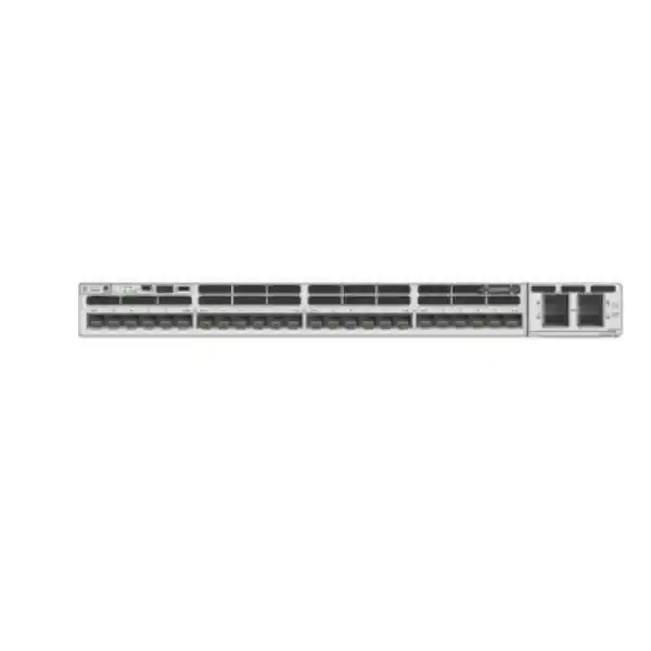
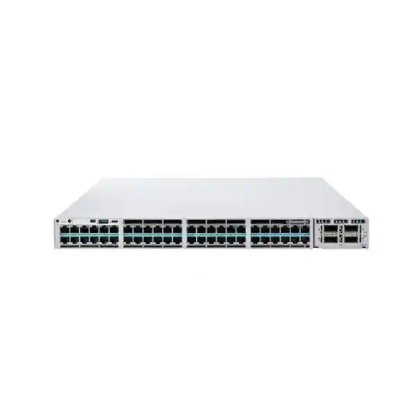
Cisco Catalyst C9300X-24HX Network Switch
The C9300X-24HX is a high-density 24-port 10G multigigabit copper switch built for organizations that need more than conventional Gigabit access. Every downlink is designed for 100 Mbps, 1, 2.5, 5 and 10 Gigabit Ethernet operation over RJ-45 copper, while Cisco UPOE+ supplies power for demanding endpoints and modular uplinks provide an upgrade path to very high-speed aggregation. StackWise-1T, the UADP 2.0sec forwarding architecture, hardware-based encryption capabilities and Cisco IOS XE make the platform a strong fit for campus, smart-building, branch, Wi-Fi 6/6E and high-performance access deployments across the UAE.
Choose the C9300X-24HX when the access layer must combine 24 copper ports capable of up to 10G, high-power PoE for modern endpoints, resilient stacking and modular uplinks that can scale into high-bandwidth distribution or core designs.
For correct UAE sizing, specify the intended uplink module, power-supply redundancy model, PoE load, software license tier, transceivers, stack cables and support coverage together rather than treating the chassis as a standalone line item.
Each downlink supports 100M, 1G, 2.5G, 5G and 10G speeds, helping preserve copper cabling investments while enabling faster endpoints.
High-power PoE capability supports demanding wireless, smart-building, video, collaboration and IoT endpoints when the power design is sized correctly.
A high-bandwidth stacking architecture allows multiple switches to operate as one logical system with resilient links, simpler management and scale-out access capacity.
Cisco’s security-focused forwarding ASIC provides dedicated hardware resources for high-performance packet processing and platform encryption capabilities.
What the C9300X-24HX is designed to solve
A modern access switch is no longer selected simply by counting desktops. In a high-performance campus, the same edge layer may feed Wi-Fi 6 or Wi-Fi 6E access points, room systems, 4K and multi-sensor surveillance, intelligent lighting controllers, building-management gateways, high-end workstations, local storage devices, industrial endpoints and ordinary 1G clients. The problem becomes multidimensional: the port must negotiate the correct data rate, deliver enough power, apply identity and segmentation policy, preserve quality of service, forward telemetry, and maintain predictable behavior during maintenance or component failure. The Cisco Catalyst C9300X-24HX is intended for this kind of converged edge.
Its most visible characteristic is the set of twenty-four RJ-45 multigigabit interfaces. Unlike a conventional 1G access switch, the C9300X-24HX can negotiate 100 Mbps, 1 Gbps, 2.5 Gbps, 5 Gbps or 10 Gbps on each copper downlink. This matters because many wireless access points and specialist endpoints now exceed a single Gigabit of real aggregate traffic but can still operate on structured copper cabling. A network team can therefore move selected devices to 2.5G or 5G immediately, reserve 10G for the highest-demand edge devices, and retain compatibility with older 1G or 100M equipment on the same switch.
The second problem is power. High-performance wireless radios, cameras with heaters or analytics, video endpoints, thin-client stations, access-control systems and smart-building devices increasingly require more than legacy PoE budgets. Cisco UPOE+ extends the power available per supported port, but an enterprise design must distinguish per-port capability from the aggregate chassis power budget. The C9300X-24HX gives the port-level capability; the final usable PoE pool depends on the installed power supplies, redundancy policy, system consumption and the number of endpoints drawing power simultaneously. That distinction is central to a reliable bill of materials.
Verified platform profile and core specifications
| Model | Cisco Catalyst C9300X-24HX |
| Downlink interfaces | 24 × RJ-45 multigigabit copper ports |
| Downlink speeds | 100M / 1G / 2.5G / 5G / 10G per copper access port |
| Power over Ethernet | Cisco UPOE+ capability on access ports; aggregate budget depends on PSU and redundancy configuration |
| Uplink architecture | Modular uplink bay; supported C9300X network modules enable high-speed fiber or multigigabit uplink designs |
| Stacking | Cisco StackWise-1T; platform support also enables resilient stack-based designs |
| Forwarding silicon | Cisco UADP 2.0sec architecture with dedicated security/encryption capability |
| Switching capacity | Up to 800 Gbps standalone for the C9300X-24HX platform profile; higher aggregate fabric figures apply when stacking bandwidth is included |
| Forwarding rate | Up to 654.72 Mpps standalone platform figure |
| Memory profile | Catalyst 9300X class platform with 16 GB DRAM and 16 GB flash in Cisco published architecture/data-sheet profiles |
| Default AC PSU class | 1100W AC supply class is commonly specified for this model; final quote should confirm PSU quantity and redundancy requirement |
| Operating system | Cisco IOS XE with license-dependent enterprise network, automation, assurance and security features |
Specification note: feature availability, software entitlements, encryption options, PoE budget and supported accessories should be validated against the ordered license, software release, PSU combination and current Cisco ordering guide at the time of quotation.
24-port multigigabit access: where the bandwidth is useful
Wi-Fi 6 and Wi-Fi 6E uplinks
A high-performance access point may aggregate more than 1 Gbps of wireless traffic, especially when multiple radios, wide channels and dense client populations are active. A 2.5G or 5G Ethernet handoff can avoid the artificial ceiling imposed by a 1G switch port. The C9300X-24HX lets the access layer negotiate the rate that matches the AP and cabling, while UPOE+ can satisfy higher radio power requirements where the endpoint and power plan support it.
High-performance workspaces
Engineering, media, CAD, visualization, geospatial and data-science users can outgrow a 1G desktop edge when moving large datasets to local storage, render farms or data-center resources. A 5G or 10G copper access port can provide a meaningful improvement without moving every desk to optical fiber. The switch can still serve standard 1G office users on adjacent ports, allowing a mixed-speed access layer without separate switch families.
Smart-building and converged services
Building systems increasingly combine data, power and policy on Ethernet. High-resolution cameras, digital signage, occupancy analytics, access control, lighting gateways and room systems create a diverse endpoint mix. The value of the C9300X-24HX is not that every device needs 10G; it is that the same access platform can serve low-speed devices, power-hungry devices and multi-gigabit devices while maintaining enterprise segmentation and operations.
Branch or compact aggregation
In a smaller site, some customers use the C9300X-24HX as a compact high-performance aggregation or collapsed-access platform. Twenty-four 10G-capable copper ports can connect servers, appliances or distribution links, while modular uplinks connect upstream over higher-speed fiber. This role requires careful routing-scale, oversubscription, optics and failure-domain design, but it can be useful where a fixed data-center switch is unnecessary or where common Catalyst operations are preferred.
UADP 2.0sec architecture and hardware security
The C9300X generation differs from a basic Layer 2 access device because forwarding, policy and security functions are designed around Cisco’s programmable UADP family. In the C9300X class, the UADP 2.0sec variant adds security-oriented hardware resources, including a dedicated encryption engine. Cisco positions the platform for hardware-assisted IPsec at high speeds, which is significant when the switch is used in new edge architectures where encrypted tunnels may extend toward data centers, cloud gateways or other sites.
From a design perspective, hardware encryption does not mean that every deployment automatically gains encrypted links simply by installing the chassis. The relevant software image, license, security feature configuration, cryptographic entitlement or key requirements, tunnel architecture and routing policy must all be considered. The benefit is architectural headroom: encryption can be implemented with forwarding silicon designed for the task rather than forcing the network to rely on an external appliance for every use case. That can simplify some campus-edge or branch designs, particularly when secure overlays are part of a larger Cisco architecture.
The forwarding pipeline also matters for ordinary campus traffic. Access control lists, quality-of-service classification, routing, segmentation, NetFlow-style telemetry and other functions consume hardware resources. The correct question is therefore not only “How many Gigabits can the switch forward?” but also “Which policies must be applied at that rate, and at what scale?” A reliable design documents anticipated MAC addresses, routed prefixes, SVIs, ACL entries, QoS policies, flow telemetry, multicast groups and endpoint identities. The C9300X platform provides strong access-layer scale, but the design should still be checked against the specific Cisco scale tables for the chosen release and feature set.
Uplink module strategy: design the northbound capacity first
A 24-port access switch in which every downlink can run at 10G has a very different potential traffic profile from a traditional 24-port 1G switch. Even though not every endpoint transmits at line rate simultaneously, the uplink must be selected from an application and oversubscription model rather than by habit. The C9300X-24HX uses modular uplinks, allowing the switch to be paired with C9300X network modules that provide different combinations of high-speed interfaces. Cisco’s platform architecture supports uplink options that can reach 100G/40G, 25G/10G or multigigabit designs depending on the inserted module.
For a dense Wi-Fi floor, two resilient 25G or higher-speed uplinks may be more appropriate than a legacy pair of 10G links, especially when many APs negotiate at 2.5G or 5G. For a high-end workstation or media floor, uplink bandwidth should reflect the possibility of synchronized transfers to shared storage. For a smart-building floor dominated by lower-rate endpoints, a smaller uplink may be sufficient even though the switch provides 10G-capable access ports. The key is to model busy-hour demand, failure conditions and traffic locality.
Failure-state sizing is often missed. If two uplinks normally share traffic, the design should ask whether one surviving link can carry the expected load after a link, optic or upstream member fails. Similarly, if the switch is part of a stack, northbound uplinks can be distributed across physical members to reduce the risk associated with one chassis or network module. Link aggregation, routing adjacency design and spanning-tree or fabric-edge behavior should be coordinated with the upstream architecture rather than added after the hardware is ordered.
Optics and cables are part of the same decision. A quotation should specify interface speed, transceiver form factor, fiber type, wavelength, distance, connector type and patching. For short rack-to-rack links, direct-attach or active optical options may be suitable where supported. For building or campus fiber, the installed plant and distance determine whether multimode or single-mode optics are required. Treating “uplink module” as a complete uplink is a common procurement error; modules, optics, fiber and upstream port compatibility must all line up.
StackWise-1T: scale, resilience and operational simplicity
Cisco StackWise-1T is one of the defining capabilities of the C9300X platform. It creates a high-bandwidth stack in which multiple physical switches can operate as a single logical switching system. For an enterprise access layer, this can simplify management, reduce the number of independent control points and provide a practical way to expand a floor or building as port demand grows. A stack can also distribute uplinks across members so that an upstream connection does not depend on one physical switch.
The design value is greater than raw stack bandwidth. A stack changes the failure domain and the operating model. Network teams should consider stack member priority, control-plane role selection, software consistency, stack cable topology, power redundancy, uplink distribution and maintenance procedures. A resilient ring topology for stack cabling is preferred to a daisy-chain that leaves a single break able to partition the interconnect. Cable lengths should be selected for the rack layout before equipment arrives, because a stack assembled with unsuitable cable lengths often leads to untidy or stressed cabling.
Stacking also influences capacity planning. If a deployment starts with one 24-port C9300X-24HX and expects to grow, the rack should reserve space, power, cooling and patch-panel capacity for future members. The upstream switch should reserve enough ports for distributed uplinks. Management addressing and monitoring should be designed around the logical stack while preserving visibility into each physical member’s health, temperature, power supply, fan state, port errors and PoE consumption.
Mixed-stack compatibility can be attractive when extending an existing Catalyst 9300 estate, but compatibility rules are model- and software-dependent. The safest procurement method is to document every existing model, stack technology, IOS XE release and intended new member, then validate the combination against current Cisco compatibility guidance. A stack is not merely a cable accessory; it is a system architecture that should be verified as carefully as routing or power.
UPOE+ power engineering: calculate watts, not just ports
Per-port capability
UPOE+ enables high power on supported Ethernet pairs and is useful for endpoints that exceed conventional PoE+ levels. The port capability is not the same as the total chassis budget. Always use the endpoint’s maximum power requirement, not its average draw, when calculating worst-case capacity.
Power-supply plan
The C9300X-24HX is commonly ordered with a high-capacity AC power supply class, and redundant supply options can be used. Whether the second PSU is reserved for full redundancy or contributes to the PoE pool affects the amount of endpoint power available after a failure.
StackPower planning
StackPower can pool power resources across compatible stack members, creating options for redundancy and more efficient allocation. It should be deliberately designed with the correct power-stack cables, PSU capacities and redundancy mode rather than assumed as a default outcome.
UPS and circuit sizing
The upstream electrical design must account for switch system power, PoE load, PSU efficiency, future growth and desired runtime. UPS VA/W ratings, PDU socket count, branch-circuit load and rack heat dissipation should be checked as part of the network bill of materials.
A useful method is to build a port-level power worksheet. List each powered endpoint, its expected maximum draw, the switch port, desired link speed and business criticality. Add an engineering reserve for future devices and for cases where endpoints briefly draw more during startup. Then model a power-supply failure. If the network must keep all critical access points and cameras online after one PSU fails, the surviving supply or shared StackPower pool must be able to support the required load. If noncritical endpoints may be shed, configure port priorities and document the intended behavior.
This power exercise is particularly important in UAE smart offices, hospitality, education and large retail environments where access switches may feed dense wireless, CCTV and building systems simultaneously. The network may remain logically healthy while an undersized PoE budget silently disables devices after a PSU fault. Correct sizing prevents that class of failure and avoids purchasing excess capacity blindly.
Cabling for 2.5G, 5G and 10G multigigabit operation
One of the reasons multigigabit Ethernet is valuable is that it can extract more performance from installed balanced copper cabling, but cable quality still matters. The negotiated speed depends on channel length, category, installation quality, patch cords, connectors, electromagnetic environment and endpoint capability. A switch port advertised for 10G does not make an unsuitable cable plant behave like a certified 10G channel. Before enabling high-speed access across an existing building, the cabling should be tested and classified.
For new installations expected to carry 10GBASE-T broadly, a high-quality Cat6A design is normally the preferred baseline because it provides stronger margin for 10G at standard horizontal cabling distances and better control of alien crosstalk. Existing Cat6 or other installed cabling may successfully operate at certain multigigabit rates or distances, but qualification testing is the responsible approach. The practical advantage of the C9300X-24HX is that it can negotiate down to 5G, 2.5G or 1G if that is the appropriate rate for a specific link.
Patch-panel density and thermals also deserve attention in high-power PoE deployments. Bundles carrying substantial DC power can experience temperature rise, and cable derating or pathway design may be relevant under local standards and installation rules. Select cabling and connectors from a reputable structured-cabling system, avoid excessive bundling where high-power PoE is widespread, and keep records of certification results. Network troubleshooting becomes significantly faster when the team can distinguish PHY negotiation errors from switching, endpoint or application issues.
For brownfield sites, a staged migration works well. Start with a cable audit, identify which runs serve high-bandwidth endpoints, test those channels, and then set expected interface speeds. Ordinary users can remain at 1G while APs or workstations move to 2.5G, 5G or 10G. This lets the organization target cabling upgrades where they produce measurable benefit instead of replacing every horizontal run at once.
Cisco IOS XE, automation and operations
The C9300X-24HX runs Cisco IOS XE, which gives the switch a modern enterprise operating model rather than a narrow fixed-function access feature set. IOS XE supports conventional CLI operations while also enabling model-driven management, APIs and automation workflows. In a mature environment, this allows network configuration to be handled as controlled data: templates can define VLANs, interface policy, routing, access control, QoS, telemetry and management services, while automation systems validate intended versus actual state.
Operational consistency becomes important when many switches are deployed across Dubai, Abu Dhabi, Sharjah or regional branches. A manual per-switch configuration method scales poorly and creates drift. The stronger approach is to define a standard access profile for device classes. A wireless AP port may require a specific native VLAN, trunk policy, PoE settings, QoS trust boundary and discovery protocol behavior. A camera port may require a restricted VLAN, storm control, authentication policy and lower trust. A user-facing port may require 802.1X, MAB fallback rules, DHCP snooping and dynamic segmentation. These intents can then be delivered consistently through automation or centralized management.
Telemetry should be designed with equal care. SNMP remains useful, but streaming telemetry, syslog, flow records and controller-based assurance can provide richer visibility. Useful baselines include interface utilization, error counters, PoE draw, device temperature, fan and PSU status, stack-ring health, CPU and memory trends, authentication failures and uplink latency or loss. The objective is not to collect every counter indefinitely; it is to collect the measurements that support capacity planning, fault isolation and service-level management.
Software maintenance should also be included in the lifecycle. Define an approved IOS XE release train, test upgrades in a representative environment, review feature compatibility, back up configuration and establish rollback procedures. Stacked designs can provide operational advantages, but maintenance behavior depends on release and feature combinations. A change plan should specify how control-plane transitions, stack-member reloads and upstream routing behave, rather than assuming an upgrade is nondisruptive under all circumstances.
License selection: Network Essentials, Network Advantage and subscription considerations
Cisco Catalyst ordering typically separates the hardware platform from software license level and subscription-based capabilities. The C9300X-24HX is available in different ordering variants, commonly associated with Network Essentials or Network Advantage, and Cisco has also expanded cloud-managed options for supported Catalyst 9300X configurations. The correct choice depends on the intended Layer 2, Layer 3, segmentation, assurance, automation and security architecture.
Network Essentials is commonly used where the access layer needs foundational enterprise switching and routing features without the full advanced feature set. Network Advantage is appropriate when more advanced routing, segmentation or policy capabilities are required. The exact feature matrix changes across software releases and commercial programs, so a purchase should not be based on a remembered feature list from an older deployment. Instead, convert the design into requirements: routing protocols, route scale, VRF needs, fabric roles, multicast, advanced telemetry, encryption, identity, controller integration and assurance. Then map each requirement to the current Cisco licensing guide.
Subscription terms are equally important for total cost of ownership. Some advanced management, analytics or assurance functions depend on subscription entitlements rather than the perpetual network license alone. The quotation should therefore identify license tier, subscription level, term length, support coverage and renewal assumptions. This prevents a common budgeting problem in which the hardware is funded but the organization later discovers that the operational feature it expected sits in a separate software entitlement.
FourTeck can align the bill of materials with the intended operating model rather than quoting an arbitrary suffix. For a UAE project, share whether the switches will be managed standalone, through Cisco campus controllers, through a cloud-managed workflow where supported, or as part of an existing enterprise standard. Also share the current Catalyst environment and license agreements so the new C9300X-24HX units can be integrated without creating inconsistent feature tiers across the estate.
Segmentation, identity and access-layer security
A fast switch can still be a weak access layer if every endpoint is placed into broad VLANs with little identity control. The C9300X-24HX is most valuable when bandwidth and power are combined with a security architecture. Common controls include 802.1X authentication for managed users and devices, MAC Authentication Bypass for endpoints that cannot perform 802.1X, dynamic VLAN or policy assignment, DHCP snooping, Dynamic ARP Inspection, IP Source Guard, port security, storm control and carefully scoped access control lists.
The design should start with endpoint classes. Corporate laptops, employee phones, access points, cameras, printers, building controllers, guest systems and vendor-maintained equipment should not automatically share the same trust level. Define what each class needs to reach and deny unnecessary east-west paths. A camera may need to communicate with video-management servers and NTP, but not user subnets. A building-management controller may need a limited application path to its supervisory server. A guest or contractor device may need internet access without internal reachability.
Multigigabit and UPOE+ capability can increase the impact of a compromised endpoint because the switch can provide substantial bandwidth and continuous power. Identity, segmentation and monitoring therefore become more important as edge capability rises. Integrating the access layer with Cisco identity or fabric solutions can automate some of this segmentation, but conventional VLAN, VRF and ACL designs remain valid when they are maintained consistently.
Management-plane security deserves separate controls. Use dedicated management addressing or VRF design where appropriate, restrict administrative protocols to trusted sources, prefer secure protocols, centralize AAA, synchronize time, protect SNMP credentials, log configuration changes and maintain role separation. The goal is that compromising an endpoint on a user port does not give an attacker an easy path to the switch management plane.
Quality of Service for voice, video, wireless and critical applications
The large aggregate bandwidth of the C9300X-24HX does not eliminate congestion. Bottlenecks can move to uplinks, WAN circuits, firewalls, servers or wireless media, and microbursts can still occur when many high-speed sources send toward a slower destination. Quality of Service should therefore be designed around business traffic classes rather than skipped because the access ports are fast.
A typical enterprise policy separates real-time voice, interactive video, network control, business-critical applications, bulk data and best-effort traffic. The trust boundary is essential. A managed IP phone or approved wireless access point may be allowed to mark packets, while an ordinary user device should not be trusted to self-classify as high priority. Classification can use DSCP, CoS, access lists, NBAR-style application recognition where licensed and supported, or controller policy. Queuing and shaping then protect latency-sensitive traffic during contention.
Wireless introduces an additional translation between wired and radio QoS. The access port must preserve the markings and trunk behavior expected by the AP and wireless controller architecture. Voice roaming, real-time collaboration and high-density lecture halls are sensitive not just to bandwidth but also to loss, jitter and queueing delay. If an AP uplink negotiates at 5G while the distribution uplink is oversubscribed, an intentional QoS model prevents one bulk transfer from consuming the full bottleneck.
Measure before and after policy changes. Interface queue drops, uplink utilization, wireless application experience and WAN performance provide evidence about whether the QoS design is working. Avoid complex class maps with no operational owner. A smaller set of well-documented traffic classes usually produces better long-term results than a highly granular policy that nobody can troubleshoot.
High availability beyond stacking
Resilience is built from multiple layers. StackWise can reduce the operational impact of a single member failure, but the access service also depends on power, uplinks, upstream devices, cabling, routing and software. A robust C9300X-24HX deployment starts by deciding which failures the network must survive without user-visible outage and which failures may cause a controlled degradation.
At the chassis level, dual power supplies can protect against a PSU fault or a feed failure when they are connected to independent electrical sources. If both supplies are connected to the same PDU and circuit, the switch may have PSU redundancy but not feed redundancy. Where high availability is required, connect supplies to separate PDUs or UPS-backed circuits according to site electrical standards. Monitor PSU state continuously and replace failed units promptly; running indefinitely on the surviving supply eliminates the intended redundancy.
At the network level, distribute uplinks across stack members and upstream devices where the architecture supports it. A port-channel can protect against a single physical link or optic failure, while routed links can remove spanning-tree dependencies in some distribution designs. The upstream pair must itself be resilient, otherwise two access uplinks that terminate on one distribution chassis still share a common failure point.
At the software level, redundancy depends on release behavior and configured features. Stateful control-plane mechanisms, fast convergence and maintenance tools can reduce interruption, but they should be tested with the exact production feature set. Authentication, multicast, routing, fabric roles and advanced security can each affect convergence behavior. A pre-production test that power-cycles a member, removes an uplink and restarts critical processes often reveals hidden dependencies before deployment.
Finally, document physical topology. Stack cables, StackPower cables, uplink fibers and power feeds should be labeled at both ends. Rack elevation drawings should show member numbers and cable paths. During an incident, clear physical records are often more valuable than another theoretical redundancy feature because they help technicians remove the correct cable or replace the correct member without introducing a second fault.
Sizing methodology for a UAE campus or branch
Count endpoint classes
List users, APs, cameras, phones, room systems, building devices, servers and specialist workstations. Identify which require PoE and which require more than 1G. Reserve realistic growth rather than filling every port on day one.
Measure speed demand
Assign expected link rates by endpoint type. A 10G-capable port does not mean every device should be forced to 10G. Use 2.5G or 5G where that matches AP or cabling capability and 10G where application demand justifies it.
Build the PoE worksheet
Record maximum device power, not only nominal draw. Add reserve. Test whether the required critical endpoints remain powered after one PSU or power-feed failure.
Size the uplinks
Estimate busy-hour aggregate demand and apply a defined oversubscription ratio. Model failure state as well as normal state. Select uplink module, optics and upstream interfaces as one compatible set.
Validate software scale
Calculate VLANs, SVIs, routes, VRFs, ACL entries, multicast, telemetry and identity requirements. Confirm the selected license and IOS XE release cover the design.
Engineer facilities
Check rack depth, RU availability, airflow, ambient conditions, dual power feeds, UPS runtime, PDU sockets, grounding and cable management. The network design is incomplete until the switch can be installed safely and cooled reliably.
Deployment topology 1: high-density wireless access floor
A common C9300X-24HX use case is a floor dominated by high-performance wireless access points. Assume a building with 12 to 20 APs, each capable of multi-gigabit wired uplink, alongside room devices and a smaller number of wired users. The switch provides enough port density to terminate the APs while leaving ports for supporting systems. Each AP can negotiate 2.5G, 5G or 10G depending on model and cabling, and UPOE+ provides power headroom for radios or USB peripherals where supported.
The uplink should not be selected by simply multiplying AP count by negotiated link speed, because wireless traffic is bursty and the wired port speed is not equal to continuous offered load. Instead, use controller statistics or design assumptions for busy-hour throughput per AP. If 16 APs are expected to average 500 Mbps during peak periods with bursts substantially higher, a pair of 25G uplinks may provide ample normal-state capacity and resilience. In an exceptionally dense event venue, faster uplinks or additional access switches may be justified.
PoE can become the dominant constraint. Sixteen APs drawing 30 to 60 watts each may consume hundreds of watts before any cameras or room systems are added. If high-power radios are used, model their maximum draw and consider whether all radios remain operational after a power-supply failure. A design that loses half its wireless capacity during a single PSU fault may not meet business requirements even if data links remain up.
Wireless management also influences VLAN and QoS configuration. Depending on architecture, AP switchports may carry a management VLAN plus tunneled or locally switched user traffic. The design should define trunking, native VLAN behavior, QoS trust, discovery protocols, authentication and controller reachability. The access switch then becomes a predictable wired foundation for the radio design rather than an isolated component.
Deployment topology 2: smart building, CCTV and digital workplace
In a smart-building design, bandwidth requirements vary widely but power and segmentation become especially important. A single C9300X-24HX might feed high-resolution cameras, access-control readers through controllers, occupancy sensors, room-booking panels, digital signage players, conference endpoints, lighting gateways and wireless APs. Most of these devices do not need 10G, yet placing them on a multigigabit UPOE+ platform can simplify standardization while reserving fast ports for the few devices that do require them.
The first design task is not speed; it is trust separation. Building devices are often managed by different vendors and may have long replacement cycles. Place them into clearly defined security zones with restricted application paths. Use identity where feasible and MAC-based controls where necessary. Deny unnecessary lateral communication. Cameras should reach video-management and time services; signage should reach content servers; building controllers should reach supervisory systems. Avoid a broad “IoT VLAN” that gives every embedded device access to every other embedded device.
The second task is power continuity. A smart building can become operationally unsafe or inconvenient if PoE is lost to door systems, critical cameras or communications endpoints. Classify powered devices by criticality. During a constrained power event, keep essential ports energized before decorative or convenience systems. UPS runtime should be based on the expected PoE load, not just the switch’s base consumption.
Finally, account for maintenance ownership. Facilities teams may own some endpoints while IT owns the switching. Create a joint port map containing endpoint name, switch/port, VLAN or policy, power expectation, vendor contact and maintenance window. This prevents repeated discovery work and reduces the risk that a network change disconnects a building service nobody realized was attached to that interface.
Deployment topology 3: high-performance workgroup or specialist lab
The C9300X-24HX can also serve a specialist workgroup where a small number of endpoints require 5G or 10G copper. Examples include design studios, engineering teams, media production, research labs, geospatial analysis and local AI or data-processing workflows. In these cases, endpoint traffic may be less bursty than ordinary office access and may involve sustained transfers to file servers, storage arrays or compute clusters. Uplink sizing therefore becomes more demanding.
Start with the data path. If twelve 10G workstations all copy datasets to a storage platform through a single 25G uplink, the bottleneck is obvious even though every access link negotiates at 10G. That may still be acceptable if synchronized transfers are rare, but the oversubscription should be intentional. If the workflow regularly drives multiple concurrent transfers, use higher-speed or multiple uplinks and verify that the upstream distribution, firewall and storage network can absorb the traffic.
Client hardware matters as much as the switch. Confirm that workstation NICs support the desired 2.5G/5G/10G speed, drivers are stable, cabling is certified and host operating systems are tuned appropriately. A user who sees a 10G link light may still experience poor performance if storage, TCP settings, security inspection or server-side throughput is the actual bottleneck. Establish an end-to-end performance baseline rather than treating link speed as the sole success metric.
This design is also a good candidate for routing at the access or distribution edge if east-west application flows benefit from local Layer 3 boundaries, but routing choices should match the enterprise architecture. Document gateway placement, VRF segmentation, multicast needs, failure convergence and security inspection paths. A fast access switch can expose weaknesses elsewhere in the architecture, which is useful: it helps the organization identify the real bottleneck rather than hiding it behind 1G access links.
UAE environmental, rack and facilities considerations
Enterprise switches are normally installed in conditioned telecom rooms, but UAE projects can expose network equipment to high ambient temperatures when closets are undersized, cooling is intermittent or racks are located near service areas. The correct solution is not to rely on the switch tolerating poor conditions; it is to engineer the room. Maintain the platform within Cisco’s published environmental limits, provide clean airflow, keep intake and exhaust paths unobstructed, monitor room temperature and avoid recirculating hot exhaust into neighboring devices.
The C9300X-24HX combines high-speed PHYs, high-power PoE and potentially substantial uplink traffic, so thermal load can be meaningful. A rack containing multiple C9300X switches, PoE loads and redundant PSUs can contribute significant heat even when user traffic is moderate. Facilities planning should estimate actual electrical input at expected PoE utilization and translate that into cooling demand. UPS systems also generate heat and require ventilation.
Airflow direction must match the rack design. Keep blanking panels where appropriate, maintain vertical and horizontal cable management, and avoid large copper bundles blocking fan intakes or exhaust. Leave enough service space to remove power supplies, fans or network modules without dismantling unrelated cabling. If a rack is close to full capacity, reserve room for future stack members and cable bend radius rather than filling every RU.
Electrical planning should use site-standard power connectors, protected circuits, proper grounding and monitored PDUs where available. Critical access closets should consider dual power sources from independent UPS paths. For remote UAE branches, where onsite technical support may not be immediate, environmental sensors and remote PDU monitoring can reduce mean time to diagnosis by revealing power or temperature problems before dispatching an engineer.
Procurement and bill-of-materials planning
A complete C9300X-24HX order is more than the base switch. The hardware suffix, network license tier, subscription term, power supplies, power cords, uplink module, optical transceivers or direct-attach cables, stack cables, StackPower accessories, console or management requirements, spare strategy and support coverage all influence whether the unit can be deployed on arrival. Procurement should therefore be driven by an approved network design rather than by copying a chassis part number into a purchase order.
The first distinction is the base software variant. Network Essentials and Network Advantage ordering options are not interchangeable if advanced routing or segmentation features are required. A design team should sign off the feature list before procurement. Where Cisco’s cloud-managed option is being considered, validate operational fit, existing management standards and licensing separately. Do not assume a cloud-managed ordering code behaves identically to an existing on-premises Catalyst process.
The second distinction is power. Confirm whether one or two PSUs are required, their wattage class, whether the second PSU is for redundancy or additional PoE capacity, and the correct power cords for the UAE installation. Then check the UPS and PDU. If StackPower is part of the resilience plan, add the correct cables and confirm compatibility across every planned stack member.
The third distinction is uplinks. Select the network module only after the upstream interface speed is known. Then add the exact optics for fiber type and distance. A 100G-capable module is not useful if the upstream device lacks a compatible port or if the installed fiber cannot support the chosen optic. Conversely, ordering only 10G uplinks for a floor with dense multi-gigabit APs can create an avoidable bottleneck.
For sourcing, warranty, deployment coordination and adjacent network requirements, customers can review FourTeck UAE, use FourTeck IT Services UAE for implementation and support discussions, explore security integration through Firewall Dubai, and coordinate compute-side connectivity through Server Dubai. These links represent separate FourTeck resources that may be relevant when the switch is part of a wider campus, firewall, server or managed-services project.
Migration from Catalyst 2960, 3650, 3850 or older access platforms
Many organizations evaluating the C9300X-24HX are replacing older 1G access switches. The migration should not simply reproduce the old configuration line for line. Older designs may contain accumulated VLANs, permissive trunks, unused port channels, legacy authentication exceptions, obsolete QoS policies and management protocols that no longer match security standards. A refresh is an opportunity to simplify and modernize the access model.
Start with discovery. Export current interface descriptions, VLAN membership, trunk lists, routing, ACLs, QoS, authentication, spanning-tree settings, PoE state and neighbor information. Compare this configuration with actual traffic and device inventory. Remove abandoned VLANs and confirm every trunk’s allowed list. Identify ports operating at unusual speed or duplex settings, because forced legacy settings can interfere with multigigabit migration.
Next, validate feature equivalence in the target IOS XE release. Syntax and defaults may differ across generations. Features that were configured locally in an older switch may now be better delivered through controller templates or policy. Authentication timers, device tracking, DHCP snooping and voice VLAN behavior should be tested with representative endpoints. If the legacy switch used special macros or platform-specific commands, translate the intent rather than copying unsupported syntax.
Then plan physical cutover. Pre-stage the C9300X-24HX with management addressing, software, licenses, base configuration and uplink settings. Label every patch cord, export the old port map and create a one-to-one migration sheet. If the new switch uses different rack depth or cable-management geometry, correct that before the maintenance window. Test the uplink and management plane before moving endpoints.
Finally, verify application behavior after cutover. Check authentication success, voice registration, AP join status, camera feeds, building-system reachability, PoE draw, negotiated link speeds, interface errors, routing neighbors and monitoring. Keep the old switch available as a rollback path until critical services are validated. A controlled migration turns the hardware refresh into a network-quality improvement rather than a risky replacement exercise.
Monitoring, baselining and troubleshooting
A multigigabit access environment needs monitoring that can distinguish several failure modes. If a user reports poor performance, the link may have negotiated at 1G instead of 5G because of cabling, the port may be erroring, the uplink may be congested, the endpoint may be CPU-limited, the server may be slow, or a security appliance may be inspecting traffic at a lower rate. A useful monitoring baseline captures both the switch state and the application path.
For each access port, collect negotiated speed, duplex, interface utilization, error counters, discards, PoE state and endpoint identity. For uplinks, collect utilization at a shorter interval capable of revealing bursts, queue drops, optical diagnostics where available and port-channel member health. For the chassis, monitor temperature, fan state, power supplies, system CPU, memory, stack-ring health and software alarms. For Layer 3 designs, add routing-neighbor state, route counts and convergence events.
When troubleshooting a multigigabit copper port, start at Layer 1. Verify both endpoints support the desired rate, check auto-negotiation, inspect cable-test results, replace patch leads and review physical error counters. A port falling from 10G to 5G or 2.5G may indicate cable limitations rather than a switch defect. When troubleshooting PoE, compare negotiated power class, actual draw, switch power budget and PSU state. If a powered device cycles under load, examine both network power and the endpoint’s own firmware.
For performance incidents, isolate the path. Test local switch forwarding, then the uplink, then distribution/core, firewall and server. Use flow telemetry to identify top talkers and traffic classes. Compare queue drops with utilization. A 25G uplink can experience microburst loss even if five-minute average utilization looks low. Shorter polling or streaming telemetry reveals these events more clearly.
Create a post-installation baseline while the network is healthy. Record normal temperature range, PoE consumption, uplink utilization, CPU, memory, error rates and key application latency. Later incidents can then be compared with a known-good state. Without a baseline, every number has to be interpreted from scratch.
When the C9300X-24HX is the right model—and when it is not
The C9300X-24HX is a strong choice when a project needs a relatively compact 24-port switch but expects substantial performance per port. It is especially compelling when many access ports need 2.5G, 5G or 10G copper and at least some endpoints need high-power PoE. It also makes sense when StackWise-1T, modular high-speed uplinks, advanced Catalyst operations or UADP 2.0sec security capabilities align with the organization’s existing Cisco architecture.
It may be excessive for an office in which nearly every endpoint is a low-power 1G desktop or phone and uplink demand is modest. In that case, a lower-cost Catalyst model with standard Gigabit access may satisfy requirements. Similarly, if a site needs forty-eight copper ports but only a small number require 10G, a different port-density mix may provide better economics. Hardware should follow the endpoint map, not the attraction of the highest specification.
It is also not a direct substitute for a purpose-built data-center switch in every server environment. Data centers can require different airflow, buffer characteristics, port density, VXLAN/EVPN features, automation models and redundant top-of-rack architecture. The C9300X-24HX can serve selected server or aggregation use cases, especially in enterprise or branch environments, but the workload and architecture should be evaluated rather than assuming all 10G switches are interchangeable.
A useful selection question is: “Which capability is driving this model?” If the answer is multi-gigabit wireless, UPOE+ smart-building power, high-performance copper workstations, StackWise-1T resiliency, 100G-class uplink options, Catalyst security integration or a combination of these, the C9300X-24HX is likely a well-targeted platform. If none of those drivers exists, a simpler switch may be more economical.
Frequently asked technical questions
Does every port support 10G?
The C9300X-24HX is designed with twenty-four multigigabit RJ-45 copper downlinks capable of 100M, 1G, 2.5G, 5G and 10G. The actual negotiated rate depends on the connected endpoint and cabling.
Can it power high-end access points?
Yes, the model supports Cisco UPOE+ on its access ports. Confirm the AP’s power requirement and calculate the aggregate PoE budget from the installed PSU and redundancy configuration.
Does it have fixed uplinks?
The C9300X-24HX uses a modular uplink architecture. Select the appropriate C9300X network module according to the upstream speed, optics and redundancy design.
What is StackWise-1T?
It is Cisco’s high-bandwidth stacking technology for supported Catalyst 9300X systems. Multiple members can operate as one logical switch with a resilient stack interconnect when designed correctly.
Can the switch do Layer 3 routing?
Catalyst 9300X supports enterprise Layer 3 capabilities, but the exact routing protocols, scale and advanced features depend on software release and license tier. Validate the feature matrix against the intended design.
Is hardware IPsec available?
The UADP 2.0sec platform includes a dedicated encryption engine and Cisco positions C9300X for high-speed hardware IPsec use cases. Required software, licenses and cryptographic entitlements must be confirmed.
Can I use existing Cat6 cabling?
Possibly, depending on channel quality, length and target speed. Test the installed links. New 10G-heavy designs commonly favor Cat6A to provide stronger margin for full-distance 10GBASE-T operation.
Should I buy one or two power supplies?
That depends on required PoE budget and redundancy. Critical sites typically evaluate dual PSUs and independent power feeds. The power worksheet should show what happens to powered endpoints after one PSU fails.
Pre-deployment configuration framework
A production deployment should enter the maintenance window with the switch largely preconfigured and validated. Begin by loading the approved IOS XE release, confirming boot variables and verifying license state. Configure management addressing, DNS and NTP, secure administrative access, AAA, logging, SNMP or telemetry, device hostname, location metadata and contact information. Disable unnecessary services and restrict management access to trusted networks.
Next, build the Layer 2 and Layer 3 foundation: VLAN database, trunks, allowed VLAN lists, spanning-tree parameters, SVIs or routed links, first-hop gateway behavior, dynamic routing and route policy. Avoid leaving trunks open to every VLAN by default. Define native VLAN handling explicitly. Where routing is used at the access layer, apply a consistent addressing and summarization plan that supports troubleshooting and avoids accidental overlap.
Then apply endpoint policy. Create interface templates for APs, phones, users, cameras, building systems and servers. Each template should specify access or trunk mode, authentication, voice VLAN if needed, PoE behavior, QoS, storm control, DHCP snooping trust, portfast or edge settings, BPDU protection and monitoring. Templates reduce configuration drift and make future automation easier.
For stacked deployments, form and validate the stack before endpoint cutover. Confirm member numbering, priorities, stack-ring state, software consistency and power-stack state. Distribute uplinks across members and verify port-channel or routing behavior with one link removed. Simulate the loss of a member where practical. The objective is to verify the failure path, not just the normal path.
Finally, save a golden configuration and operational snapshot. Record software version, serial numbers, licenses, power supplies, uplink modules, optics, stack cables, port map, baseline CPU and memory, PoE budget and environmental readings. This becomes the reference for future changes and incident response.
Lifecycle, spares and support strategy
Enterprise access switching is a multi-year investment, so the operational plan should extend beyond installation. Maintain an asset register with chassis serial number, license information, support contract, software release, stack membership, location and installed accessories. When multiple sites use the same C9300X standard, consistency makes sparing and troubleshooting easier because a replacement switch can be pre-staged with the same approved software and configuration templates.
Spare strategy depends on site criticality and replacement lead time. A large UAE campus may justify an onsite cold spare chassis, one or more spare power supplies and selected optics. Smaller branches may rely on a centralized spare pool with defined courier or engineer response. Optics and patch cables often fail more frequently than chassis hardware and are inexpensive to hold in stock, so a modest spare set can reduce downtime materially.
Software lifecycle should be governed. Do not upgrade purely because a newer release exists, and do not remain indefinitely on an old release because the current one “works.” Track security advisories, bug fixes, feature requirements and Cisco recommended releases. Maintain a lab or pilot group that represents the production design. Test authentication, routing, stacking, PoE, wireless integration and monitoring before broad rollout.
Configuration backup should be automated and versioned. When a change causes an incident, the team should be able to compare the current configuration with the last known-good state. For controller-managed networks, retain controller backups and document dependency between controller version and switch software. Maintain an emergency procedure for recovering a switch when centralized management is unavailable.
Support coverage should align with business impact. A critical hospital, finance environment, airport service or manufacturing facility may require faster hardware replacement and access to advanced technical support than a noncritical office. Include the support SKU and term in the original procurement conversation so the operational team is not left with enterprise hardware but inadequate response coverage.
Performance interpretation: 800 Gbps switching capacity and real-world traffic
Cisco publishes an 800 Gbps switching-capacity figure and a 654.72 Mpps forwarding figure for the C9300X-24HX platform profile in standalone operation. These figures describe the capacity of the switching system under defined conditions; they should not be interpreted as a guarantee that every application will experience 800 Gbps of usable throughput. Real-world performance depends on packet size, uplink design, traffic direction, policy, endpoint capabilities and external bottlenecks.
The distinction between bandwidth and packets per second matters. A stream of large Ethernet frames consumes bandwidth with fewer packet-processing events than the same bandwidth composed of minimum-size packets. Forwarding-rate specifications help characterize how the platform handles packet-intensive workloads. In ordinary campus access, traffic is a mix of packet sizes, and the switch is rarely driven uniformly at maximum load across every port.
Oversubscription is therefore not inherently a problem. It is a design ratio. Twenty-four 10G-capable downlinks represent a large theoretical edge capacity, but most access endpoints are idle much of the time and transmit in bursts. A pair of appropriately sized uplinks can serve the floor efficiently if the busy-hour aggregate is understood. Problems arise when oversubscription is accidental, when synchronized workflows are ignored, or when a surviving uplink after failure is too small.
Application testing should focus on end-to-end objectives. For wireless, measure client throughput, latency and roaming experience. For workstation access, measure file-transfer and application times. For CCTV, verify sustained stream delivery without drops. For voice and video, measure jitter and packet loss. For security tunnels, validate encrypted throughput with the intended feature set. These metrics are more meaningful to the business than a chassis headline number by itself.
Capacity should be revisited after deployment. Trend uplink utilization, queue drops and endpoint speeds over months. If the number of 5G or 10G clients grows, the modular uplink architecture gives a path to increase northbound capacity without replacing the entire access switch, provided the upstream architecture was planned for growth.
Security tunnel and edge use cases
The security-focused UADP 2.0sec architecture creates design options beyond traditional campus switching. Cisco describes high-speed hardware IPsec capability on Catalyst 9300X, which can support architectures where traffic is encrypted from a branch or campus edge toward another trusted network zone. This can be useful when organizations are reducing reliance on a purely perimeter-centric model and extending secure connectivity toward cloud or distributed environments.
A tunnel-capable switch should not be treated as a universal firewall replacement. Stateful inspection, advanced threat prevention, web filtering, malware analysis, application control and remote-access VPN are specialized security functions that may still belong on a dedicated firewall platform. Hardware IPsec on the switch is most useful when the requirement is secure transport integrated with routing and switching, and when the broader security policy defines where inspection occurs.
Before selecting this architecture, document tunnel count, expected encrypted throughput, route exchange, failover behavior, key management, cryptographic standards, MTU overhead and monitoring. Encryption adds headers, which can reduce effective payload MTU and may expose fragmentation problems if not planned. Routing should converge correctly when a tunnel or upstream path fails. Security monitoring should capture tunnel state and unusual traffic without creating operational blind spots.
Licensing and cryptographic entitlement are essential validation points. Cisco has specific requirements for high-scale encryption features in some Catalyst configurations. The design and quotation should therefore be reviewed against current ordering and software documentation. The value of the hardware capability is significant, but successful use depends on the complete software, licensing and operational architecture.
Decision recap: who should shortlist the C9300X-24HX?
Shortlist it when
You need twenty-four copper access ports with flexible 100M-to-10G negotiation, multiple high-bandwidth wireless APs, high-power PoE endpoints, StackWise-1T resilience, modular high-speed uplinks, advanced Cisco campus integration or security-focused UADP 2.0sec capabilities.
Size carefully when
Many endpoints will draw high PoE power, several ports will run sustained 10G traffic, the switch is used for aggregation, a single PSU must carry critical loads, or the uplink design must survive a member or link failure without congestion.
Choose another model when
The site only needs standard 1G access, does not need high-power PoE, requires a different port density, or has a data-center architecture whose airflow, buffer, port-form-factor or fabric requirements are better matched by a dedicated data-center switching family.
Procure as a system
Order the chassis together with license tier, subscription, PSU configuration, UAE power cords, uplink module, optics, stack cables, StackPower accessories, support term and any required spares. A complete BOM prevents deployment delays.
Quotation input checklist
For an accurate Cisco Catalyst C9300X-24HX UAE quotation, provide the following engineering inputs. This information lets the hardware, licenses, optics, power and support be matched to the intended deployment instead of quoting an incomplete chassis-only configuration.
Build the C9300X-24HX BOM around your actual access-layer demand
For most enterprise projects, the chassis decision is only the first 20 percent of the work. The remaining value comes from selecting the correct software tier, power redundancy, uplink module, optics, stack architecture, cabling, segmentation policy and support plan. FourTeck can use your endpoint and topology data to produce a deployment-oriented bill of materials for UAE environments.
Provide the site count, expected access speeds, PoE device list, uplink requirement and existing Cisco environment. The resulting design can then be checked for normal-state capacity, single-failure capacity, software feature fit and practical installation requirements before purchase.
Best information to send first
• Number of C9300X-24HX switches required
• AP/camera/phone/workstation counts
• Highest PoE endpoint wattage
• Desired uplink speed and fiber type
• Standalone versus StackWise design
• License and support expectations

Reviews
There are no reviews yet.