
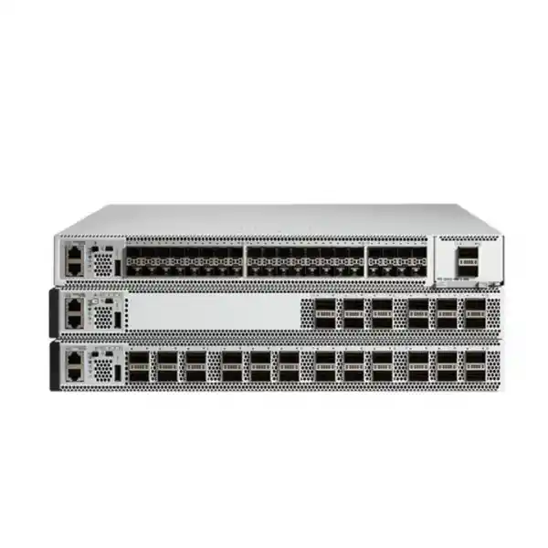
Cisco Catalyst C9500-12Q Network Switch
A 12-port 40 Gigabit Ethernet QSFP+ platform for enterprise campus core, distribution, resilient aggregation and high-bandwidth routed backbone designs. The C9500-12Q combines flexible 40G and 4x10G breakout connectivity with Cisco IOS XE operations, redundant power capability and an enterprise feature set suitable for organizations modernizing converged networks across Dubai and the wider UAE.
Designed for high-capacity campus or aggregation links, inter-switch trunks and routed core connectivity.
Each supported QSFP+ interface can be configured for four 10GbE breakout lanes, allowing mixed 40G and 10G designs.
Supports resilient power architecture for enterprise installations where single-component failures must not interrupt the switching core.
Enterprise routing, automation, telemetry, policy and programmability capabilities within Cisco’s modern campus operating environment.
What the Cisco Catalyst C9500-12Q is designed to do
The Cisco Catalyst C9500-12Q is a fixed-configuration enterprise switch intended primarily for core and distribution roles rather than access-layer edge connectivity. Its twelve QSFP+ front-panel interfaces are natively suited to 40 Gigabit Ethernet, which makes the platform useful where multiple high-capacity uplinks need to converge into a compact 1RU chassis. In practical enterprise architecture, those links may connect distribution blocks, server rooms, large access-switch stacks, firewall clusters, data-center leaf or aggregation systems, WAN routers, campus buildings or other switching cores. The value of the model comes from combining high-speed density with the Layer 2 and Layer 3 capabilities expected from the Catalyst 9500 family.
For UAE organizations, the C9500-12Q can still be relevant in brownfield networks where the installed design, optics estate, cabling plant and operational runbooks were standardized around 40GbE QSFP+. It can also be relevant when an organization needs a compatible spare, an expansion unit for an existing architecture or a controlled lifecycle replacement that preserves current topology while a broader modernization program is planned. At the same time, procurement must account for the platform’s lifecycle status. Cisco announced end of sale for the C9500-12Q, with the hardware end-of-sale date having passed on 30 April 2024. Cisco identifies the C9500-32QC as the migration replacement in the lifecycle bulletin. That means a responsible procurement decision in 2026 should distinguish clearly between maintaining an existing C9500-12Q environment and designing a new greenfield core.
FourTeck approaches the C9500-12Q as an engineering decision rather than simply a line-item purchase. The design review should confirm port requirements, optical reach, breakout usage, routing scale, software release compatibility, licensing expectations, high-availability method, rack power, airflow direction, support entitlement and the organization’s migration horizon. This is especially important for enterprise customers in Dubai where network downtime can affect branch connectivity, payment systems, cloud access, voice services, building systems, surveillance, hospitality operations, logistics platforms and business-critical application traffic simultaneously.
Organizations planning a broader UAE refresh can also align switching with firewall, server and infrastructure services. FourTeck’s UAE technology portfolio provides a wider context for network modernization, while dedicated Firewall Dubai solutions can be considered when the switch will sit adjacent to a resilient security edge or data-center firewall cluster.
C9500-12Q hardware architecture and port model
Twelve native 40GbE interfaces
The switch provides twelve front-panel QSFP+ interfaces. With standard 40G QSFP+ optics or supported direct-attach connectivity, each interface operates as a single 40GbE port. This gives the platform a compact physical port layout that is well suited to aggregation and core designs where fewer high-bandwidth links are preferable to large numbers of lower-speed physical uplinks.
10GbE breakout operation
With a supported dual-mode breakout cable, a 40G interface can be configured as four independent 10GbE interfaces. Administrators can mix native 40G ports and broken-out 10G ports on the same chassis. This is useful for gradual migration, mixed-speed aggregation or connecting multiple 10GbE devices without replacing the core platform.
Redundant power design
The C9500-12Q chassis includes two power-supply slots. Enterprise deployment normally uses both slots so power can be fed from independent PDUs or UPS-backed sources. Redundant feeds reduce exposure to a failed PSU, PDU branch or upstream power event, provided the surrounding rack electrical design is engineered correctly.
1RU rack footprint
The chassis occupies one rack unit. Cisco’s hardware guide lists dimensions of approximately 4.4 × 44.5 × 56.7 cm for this model family grouping. That depth, along with cable bend radius and rear power access, should be checked against the intended rack before procurement.
Understanding 40G QSFP+ and 4x10G breakout in real deployments
The C9500-12Q is often selected or retained because of its unusual combination of native 40G density and flexible 10G breakout. A native 40G QSFP+ port carries four electrical or optical lanes as a single logical Ethernet interface. When a supported breakout assembly is used, those four lanes are exposed as four independent 10GbE interfaces. Cisco’s interface documentation describes the C9500-12Q as supporting both modes and allows a mixture of native 40G modules and 4x10G breakout cables across the chassis.
This matters when sizing the switch because the raw port count alone can be misleading. An organization may need only six 40G trunks today but could require sixteen 10G device connections for servers, firewalls, storage gateways or legacy distribution switches. Rather than consuming a separate 10G aggregation platform, selected QSFP+ interfaces can be broken out to satisfy those links. Conversely, a network that starts with 10G breakouts can later return specific ports to 40G mode as downstream platforms are upgraded. The switch therefore supports a useful transitional architecture between 10GbE and 40GbE environments.
Breakout planning must be treated as a logical interface redesign, not only a cabling change. Interface names and numbering change when a port is converted from a native FortyGigabitEthernet interface to TenGigabitEthernet breakout interfaces. Configuration templates, monitoring systems, interface descriptions, QoS policies, port-channel definitions, routing adjacencies and documentation should all be updated accordingly. During a maintenance window, the engineering team should validate the configuration command sequence, save rollback points and confirm that the intended software release supports the chosen breakout workflow.
The physical medium must also be selected carefully. Short intra-rack or adjacent-rack links may use direct-attach copper assemblies where supported and operationally appropriate. Longer links may require multimode or single-mode optical transceivers with matching fiber type, connector format and optical budget. When breaking a QSFP+ interface into four 10G optical links, the transceiver or breakout assembly must match both the switch side and the remote SFP+ endpoints. Fiber polarity, patch-panel mapping and labeling become especially important because one QSFP+ port fans into four independently managed Ethernet paths.
For procurement, a bill of materials should identify every port’s planned operating mode, optic type, reach, connector, fiber type and remote endpoint. This prevents a common problem in which the chassis arrives but the transceiver mix does not match the actual topology. FourTeck can incorporate this mapping into a structured UAE deployment plan that also accounts for firewall and server interconnects through its IT services in the UAE and server infrastructure practice in Dubai.
Example port-planning patterns
Campus core pair
Use native 40G links between core and distribution blocks, then reserve breakout ports for 10G firewall, WAN or services-layer connectivity. This pattern keeps high-volume east-west and north-south transit on 40G while using 10G only where endpoint capacity requires it.
Collapsed core
In a medium enterprise, a resilient pair can aggregate access stacks, server networks and security appliances without introducing a separate distribution tier. The design must still include failure-domain analysis, sufficient routed capacity and carefully planned maintenance procedures.
Mixed 40G / 10G aggregation
Native QSFP+ ports connect newer 40G-capable devices, while selected interfaces break out to four 10G lanes for older infrastructure. This can reduce migration pressure while preserving a clear path toward higher-speed links.
Data-center service aggregation
The platform can aggregate security appliances, server blocks or service nodes where 10G and 40G coexist. It should not be treated as a generic modern leaf replacement without checking oversubscription, EVPN/VXLAN requirements, lifecycle and current Cisco migration options.
Layer 2 switching, Layer 3 routing and enterprise segmentation
A core switch is valuable only when its forwarding behavior aligns with the network architecture. The Catalyst 9500 family is designed for enterprise core and distribution use, so the C9500-12Q can participate in routed core designs, traditional VLAN-based distribution, multicast networks, policy-driven segmentation and high-availability topologies. The exact feature set available to a given unit depends on software release, license level and configuration. Before implementation, administrators should map required protocols and features to the selected Cisco IOS XE release rather than assuming every Catalyst 9500 feature is available in every image or license combination.
At Layer 2, enterprise designs commonly require VLAN trunking, spanning-tree control, EtherChannel or routed alternatives to large failure domains. A modern deployment should minimize unnecessary Layer 2 extension across the core because large broadcast domains increase operational complexity and can amplify faults. Where possible, routed point-to-point links between distribution and core layers create clearer boundaries. The C9500-12Q’s high-speed ports are particularly well suited to those routed interconnects, while remaining able to transport VLAN trunks when an application or migration design requires them.
At Layer 3, routing protocol choice should follow the operational model. OSPF remains common in enterprise networks because of its standards-based interoperability and structured area design. BGP is increasingly used inside data centers, multi-site networks and sophisticated campus fabrics because it scales policy and path control well. Static routing still has a place at small boundaries, but a core with multiple redundant paths generally benefits from dynamic routing. The routing design should define convergence targets, summarization boundaries, equal-cost paths, failure detection behavior and policy controls before configuration begins.
Cisco’s published scale templates for C9500-12Q-era models show that hardware resource allocation can vary by distribution, core, NAT and other template choices. This is operationally important because forwarding resources are finite. Route scale, host entries, MAC addresses, multicast state, ACL entries and other hardware tables compete for ASIC resources according to the selected template. Engineers should therefore size the switch against actual table requirements, especially in large networks with extensive routing, VRFs, multicast, security policy or endpoint scale.
Segmentation can be implemented at several layers. Traditional designs may use VLANs and VRFs to isolate departments, tenants, operational technology, guest networks, payment systems or management traffic. More advanced Cisco campus architectures may introduce policy constructs, overlays or software-defined access functions, subject to licensing and software support. In every case, the design should define where segmentation is enforced, how routes are leaked or filtered between zones, which firewall boundaries are mandatory and how monitoring systems identify policy violations.
Routing and switching scale considerations
| Planning area | What to measure | Why it matters |
|---|---|---|
| Routes | IPv4 and IPv6 prefixes, host routes, VRF-specific entries and projected growth. | Hardware route tables must comfortably accommodate steady-state and failover conditions. |
| MAC addresses | Active endpoints, virtualization density, Layer 2 extensions and growth. | Large L2 domains can consume table space and increase fault propagation. |
| ACL / QoS | Policy entries, classification rules, control-plane protection and service markings. | Policy scale consumes specialized hardware resources and must be validated before rollout. |
| Multicast | Groups, sources, receivers and convergence expectations. | Video, market data, IPTV and building systems can create substantial multicast state. |
| Telemetry | Flow visibility, sampled statistics, streaming telemetry and monitoring frequency. | Observability should be engineered so troubleshooting data remains available during congestion or incidents. |
High availability: designing beyond a single switch
A core switch should not be deployed as a single point of failure simply because the chassis itself supports redundant power. True availability is achieved through system design. Most production enterprise cores use a pair of switches with diverse physical connections, independent power paths and a control-plane strategy that allows traffic to continue if a switch, link, optic, line-side cable or maintenance activity removes one path. The exact implementation depends on whether the network uses routed links, port channels, first-hop redundancy, StackWise Virtual capabilities supported by the chosen platform and software, or another validated Cisco architecture.
The most important design principle is failure independence. If both C9500-12Q switches are powered from the same UPS output, share the same fiber tray, connect to the same upstream device through a single physical path or rely on a single downstream aggregation switch, then a nominally redundant topology may still fail as one system. High availability reviews should trace power, optics, cabling, routing, software and operational dependencies end to end. The team should ask what happens when any one element is removed, and then repeat the test for realistic compound events such as a link failure during a maintenance window.
Link aggregation can improve both capacity and resiliency when correctly designed. Multiple 40G links can be grouped where protocol and topology permit, but bandwidth sizing should never assume perfect traffic distribution across all member links. Hash-based load balancing means a single large flow may remain pinned to one member. Engineers should size for realistic flow patterns, not simply multiply the number of links by 40 Gbps. Likewise, failover calculations should verify that remaining members can carry peak traffic after one or more links are lost.
Routing convergence is another critical layer. When a link or node fails, the routing protocol must detect the event, calculate an alternate path and install forwarding state quickly enough for the applications that depend on it. Voice, financial systems, cloud applications, industrial control and live video may have very different tolerance for packet loss and interruption. The design should include target convergence behavior, failure-detection timers, route summarization and path diversity rather than relying on default settings without testing.
Operational resilience also requires a maintenance model. Software upgrades, optic replacements, rack work and configuration changes should be rehearsed against a runbook. The runbook should state pre-checks, traffic-drain or failover steps, verification commands, rollback conditions and post-change monitoring. In a lifecycle-sensitive platform such as the C9500-12Q, maintenance planning should additionally consider support entitlement, available software images and the organization’s migration timetable.
Cisco IOS XE, automation and network operations
Cisco IOS XE provides the operating framework for the Catalyst 9500 family. For enterprise teams already using Catalyst switching, this continuity can simplify command-line workflows, configuration standards, telemetry integration and troubleshooting processes. However, software release selection should be deliberate. A production network should use a release train that matches the hardware, licensing, feature requirements and support policy of the organization. Engineers should also verify known caveats, interoperability and upgrade paths before any change.
Modern operations increasingly depend on APIs and machine-readable telemetry rather than manual CLI inspection alone. IOS XE platforms support programmability capabilities that can be used with automation frameworks, centralized controllers and monitoring systems. The practical goal is not automation for its own sake; it is consistent configuration, faster validation and lower risk. Common use cases include checking interface descriptions, verifying routing neighbors, detecting configuration drift, collecting optics diagnostics, validating software versions and confirming that redundant paths remain healthy.
A well-managed C9500-12Q should be integrated into enterprise monitoring from the start. Capacity dashboards should track interface utilization and errors. Environmental monitoring should detect power-supply, temperature or fan alarms. Routing monitoring should identify adjacency changes and route-count anomalies. Log collection should preserve enough history to correlate incidents with changes. Flow or telemetry systems can help determine which applications generate traffic and whether congestion is concentrated in particular paths.
Configuration governance is equally important. Core changes should use version-controlled templates, peer review and defined rollback procedures. Credentials and administrative access should be protected through centralized authentication where appropriate. Management interfaces should reside in controlled networks, and management-plane ACLs should restrict who can reach SSH, APIs, SNMP or other services. Backups must be tested for restoration, not merely collected.
Security controls at the switching core
The switching core is not a replacement for a firewall, but it is an important security enforcement and visibility point. Control-plane protection helps prevent routing or management traffic from overwhelming the CPU. Infrastructure ACLs can limit access to management and routing services. Segmentation through VRFs or VLAN boundaries can reduce lateral movement. Logging and telemetry can expose abnormal paths, unexpected interfaces or sudden traffic changes. These controls should be part of a layered architecture that also includes dedicated firewalls, identity systems, endpoint controls and secure management practices.
Access to the switch itself should follow least-privilege principles. Administrative identities should be individualized rather than shared. Authentication, authorization and accounting can be centralized through enterprise identity infrastructure. Emergency local accounts may still be necessary, but they should be tightly governed. Unused management services should be disabled, cryptographic settings should follow current organizational policy, and configuration backups should be secured as sensitive information because they may contain addressing, topology and policy details.
The management plane should be isolated from user traffic whenever practical. A dedicated management VRF or out-of-band network gives operations teams a path to the device during production-network incidents. If management must share production links, ACLs and routing policy should restrict exposure. Monitoring systems should alert on failed logins, configuration changes, unexpected reloads, PSU alarms and routing-neighbor instability.
Lifecycle status is itself a security consideration. Cisco’s C9500-12Q lifecycle bulletin states that the end of software maintenance releases occurred on 30 April 2025, while the end of vulnerability and security support is listed as 30 April 2029 for entitled hardware. Organizations operating the switch in 2026 should understand exactly what support remains available under their contract and should maintain a migration plan before final support milestones are reached.
Important 2026 lifecycle note for C9500-12Q procurement
The C9500-12Q is not a current greenfield hardware choice in the same way as an actively sold Catalyst platform. Cisco’s lifecycle announcement states that the hardware end-of-sale date was 30 April 2024 and identifies the C9500-32QC as the migration replacement. The bulletin lists the last date of support as 30 April 2029, subject to applicable service-contract or warranty terms, and the last service-contract renewal date as 29 July 2028. These dates should be reviewed against the customer’s exact entitlement before any operational assumption is made.
For an existing UAE installation, there are still valid reasons to source a C9500-12Q: maintaining hardware consistency, restoring a failed unit, expanding a brownfield architecture that cannot yet be redesigned, keeping a lab identical to production or bridging a defined period before migration. The procurement process should document why the model is required, how long it is expected to remain in service and what replacement project will follow.
For a new campus core, a lifecycle review should normally compare the C9500-12Q requirement with Cisco’s indicated replacement and with current Catalyst 9500/9500X options that better match long-term port speeds, support horizon and architectural needs. FourTeck can quote the requested C9500-12Q where available while also documenting a migration alternative so technical and commercial stakeholders can make an informed decision.
Optics, cabling and physical-layer design
High-speed switch deployment succeeds or fails at the physical layer. The C9500-12Q’s QSFP+ interfaces require a carefully matched transceiver and cable strategy. The engineer must know the distance between endpoints, whether the path is direct or passes through structured cabling, what fiber type is installed, how many connectors or splices exist and what optical modules the remote equipment supports. A generic request for “40G optics” is not sufficient because different optics are designed for different reaches, fiber media and link architectures.
Inside a data room, direct-attach copper or active optical assemblies can simplify short links if the chosen components are supported and the cable routing is manageable. Between racks, floors or buildings, optical transceivers are usually preferred. Multimode fiber can be effective for shorter distances, while single-mode is often chosen for longer reach and for infrastructure intended to survive multiple generations of Ethernet upgrades. The decision should consider existing patch panels, transceiver cost, planned reuse and future bandwidth.
Breakout cabling introduces another design dimension. A single QSFP+ port may fan out into four SFP+ endpoints. Each lane needs a unique label at both ends and must map to the correct logical TenGigabitEthernet interface. Documentation should show the QSFP+ parent port, breakout lane, destination device, destination port and service carried. Without that discipline, a simple cable move can disrupt the wrong application or create difficult troubleshooting during a fault.
Optical diagnostics should be captured during commissioning. Transmit power, receive power, temperature and other available DOM values provide a baseline for later fault isolation. Interfaces should be checked for CRC errors, drops, flaps and negotiation issues. The team should also verify that fiber polarity and connector cleanliness meet requirements. Contaminated connectors are a frequent cause of marginal optical links and should be addressed with proper inspection and cleaning procedures rather than compensated for by changing configuration.
In Dubai data centers, cable-management discipline is particularly important because dense racks may combine switching, security appliances, servers, power distribution and patching in limited space. QSFP+ cables should not be bent beyond their rated radius, obstruct airflow or block removal of adjacent optics and power modules. Rack elevation drawings should reserve space for cable organizers and service loops while preserving front-to-back airflow.
Power, cooling, rack and environmental planning
Cisco’s hardware documentation lists the C9500-12Q in the 1RU chassis group with two power-supply slots. A production core should normally be installed with redundant supplies and independent power paths. The rack design should map each PSU to a separate PDU where the facility supports A/B power. If both PSUs connect to the same strip, the chassis has power-supply redundancy but not true feed redundancy.
Cooling must be matched to the selected fan and PSU airflow orientation. Data-center racks are typically engineered around cold-aisle intake and hot-aisle exhaust. Reversing airflow relative to the rack plan can cause recirculation and elevated temperatures even when room ambient conditions are within range. Before installation, verify the airflow direction of the exact unit and accessories, the rack’s front/rear orientation and the placement of blanking panels.
The documented chassis depth is more than half a meter, so rack depth must be checked along with space for rear connectors and power leads. In shallow wall cabinets or older communications rooms, this can be a constraint. A complete site survey should measure usable rail depth, door clearance, rear cable space and weight capacity. It should also verify that rack grounding and bonding follow the facility standard.
Power sizing should include both steady-state and resilience scenarios. UPS and PDU design should remain within safe load limits if one feed is lost and the surviving feed must carry the full switch load. The same analysis should include adjacent routers, firewalls and servers because an A/B architecture fails if every device transfers to one overloaded PDU during an outage. Environmental monitoring should alarm before thermal or power conditions become service-affecting.
Licensing, software entitlement and feature planning
Catalyst 9500 deployments must be sized in both hardware and software terms. C9500-12Q variants have historically been associated with Network Essentials and Network Advantage license levels, while Cisco DNA or Catalyst software subscriptions may apply depending on the procurement bundle and deployment era. Exact entitlement should be verified against the product identifier, smart account and Cisco contract records. A second-hand chassis or spare unit does not automatically imply transferable software rights or active support.
Feature planning should begin with a requirements matrix. List each protocol, scale target and operational function the network requires: dynamic routing, VRFs, multicast, advanced telemetry, segmentation, automation, redundancy, policy, controller integration and any encryption or service functionality. Then map those requirements to the exact IOS XE train and license level. This avoids discovering after installation that a key feature requires a different entitlement or release.
Software lifecycle is especially significant because the C9500-12Q has passed end of sale. Cisco’s published lifecycle milestones should be incorporated into the change calendar. The organization should know which image it intends to run, how long that image can be supported, what security support remains and when the hardware must leave production. Long-lived enterprise systems should never rely on an undefined “we will upgrade later” assumption.
For spares, the configuration and software strategy should be documented before a failure. The spare should be checked for compatible ROMMON, IOS XE image, licensing state, optics and configuration restore procedures. A cold spare that cannot assume production duties without several hours of software remediation is not an effective continuity asset.
Where the C9500-12Q fits in UAE enterprise networks
Corporate campus
Aggregate multiple buildings or distribution blocks over 40G, provide routed connectivity toward data-center and WAN services, and use breakout interfaces for selected 10G service appliances.
Hospitality and mixed-use estates
Converge high-volume guest, corporate, building-management, surveillance and service networks at a resilient core while preserving segmentation and policy boundaries.
Logistics and industrial sites
Provide high-speed routed aggregation between warehouses, control networks, offices and centralized services, with careful separation of operational technology from general IT traffic.
Education and large institutions
Support high-density access aggregation, Wi-Fi backhaul, research traffic, video services and server connectivity, subject to route, multicast and policy sizing.
Brownfield data rooms
Maintain compatibility with existing 40G optics and 10G breakout designs where a full network refresh is not yet approved, while preparing an orderly migration path.
Disaster-recovery infrastructure
Match an installed production architecture in a DR environment when operational consistency is more important than introducing a different hardware generation mid-cycle.
Sizing methodology: how to determine whether 12Q is enough
Correct sizing begins with topology, not with the switch model. Build a port map of every required connection and classify each as 10G breakout or native 40G. Then identify which links must be duplicated across two switches for redundancy. A design with eight downstream systems can easily consume sixteen physical switch-side connections when every system is dual-homed. The capacity calculation must therefore use resilient topology rather than the minimum number of links needed during normal operation.
Next calculate bandwidth under failure conditions. If two 40G links normally share traffic but one may fail, the remaining 40G link must be able to carry the expected load without unacceptable congestion. Where 10G breakouts are used, a group of four logical interfaces shares the physical QSFP+ parent’s lane structure but operates as independent Ethernet links. Oversubscription should be evaluated from endpoint to core and from core to upstream services.
Routing scale must be measured separately from throughput. Count expected IPv4 and IPv6 prefixes, host routes, VRFs, multicast entries and policy objects. Include growth and contingency. During a routing event, temporary table usage can be higher than steady state, so a design running close to maximum capacity is fragile. Cisco’s template-based hardware allocation means the appropriate forwarding template must also be selected for the workload.
Traffic characteristics matter as much as headline bandwidth. A network dominated by a few elephant flows behaves differently from one carrying thousands of smaller flows. Port-channel hashing, queue utilization and burst patterns can create congestion even when average utilization looks modest. Monitoring data from the existing network should be analyzed at short intervals so bursts are not hidden by hourly or daily averages.
Finally, apply lifecycle headroom. A switch that meets today’s needs but cannot support the organization’s required operating horizon may be a poor choice. Because the C9500-12Q is already end of sale, a new procurement should have a clearly defined role and exit plan. If the requirement is for a five-to-seven-year greenfield core, the design should be compared with current Cisco alternatives before purchase.
The result of sizing should be a documented engineering decision containing port count, bandwidth, route scale, licensing, optics, resiliency and lifecycle. That document becomes the basis for a defensible bill of materials and avoids treating the switch as an isolated SKU.
Illustrative design: resilient dual-core with mixed 40G and 10G
Consider a Dubai enterprise with two campus distribution blocks, a firewall cluster, two WAN routers and a server aggregation layer. A pair of C9500-12Q switches can be arranged so each distribution block has diverse connectivity to both cores. Native 40G links carry the primary aggregation traffic. Selected QSFP+ interfaces are broken out to 4x10G for devices that do not require 40G, such as WAN routers or security appliances with 10G interfaces.
In such a design, the inter-core relationship must follow the chosen Cisco high-availability architecture. Some networks may use Layer 3 links and independent control planes; others may use a validated virtualization technology. The correct choice depends on requirements such as multi-chassis EtherChannel, gateway behavior, convergence, maintenance strategy and software support. Engineers should avoid copying an old topology simply because it is familiar if a routed design would reduce failure domains and operational complexity.
The firewall cluster should be connected so a single core failure does not isolate security services. If each firewall node has multiple 10G interfaces, breakout groups can supply those links efficiently. However, the switching and firewall HA mechanisms must be tested together. Stateful firewall failover, routing adjacency behavior, ARP/ND convergence and upstream path selection can interact in ways that are not visible in a simple diagram.
The WAN routers can be dual-homed to the cores using routed 10G links. Dynamic routing advertises reachable prefixes and provides path failover. Policy should prevent accidental transit where not intended and should define route preference during partial failures. The server aggregation layer may use 40G port channels or routed uplinks depending on the data-center architecture.
Commissioning should simulate failures one at a time: remove a distribution uplink, disconnect one firewall link, power off one core, disable a routing adjacency and test a PSU feed. Application owners should verify service behavior while network engineers confirm convergence and monitoring alerts. The objective is not simply to prove that links go green; it is to prove that real services remain available under the failures the architecture was designed to survive.
Migration from older Catalyst or mixed-vendor cores
Migrating a core switch is one of the highest-risk changes in an enterprise network because many services converge at the same point. The safest approach is usually staged migration rather than a single large cutover. First, document the existing topology, routing, VLANs, trunks, port channels, first-hop redundancy, ACLs, QoS, multicast, management access and monitoring. Then identify obsolete configuration that should not be carried forward.
A lab or pre-production validation should test critical feature behavior on the target IOS XE release. Special attention should be given to optics, breakout configuration, routing neighbors and high-availability functions. Configuration syntax may differ between software generations, and older operational habits may no longer be best practice. The migration design should separate “must preserve” requirements from “historical configuration that happens to exist.”
Physical migration should be planned cable by cable. Every existing port should map to a new port identifier, optic and peer. Breakout interfaces deserve extra attention because one parent QSFP+ port corresponds to four logical 10G endpoints. Labeling should be completed before the maintenance window wherever possible. Temporary patching and rollback paths should be documented.
Routing migration can often be staged by building new adjacencies in parallel, preferring old paths initially, then shifting traffic by policy or metrics. This allows verification before the legacy core is removed. Layer 2 migrations can be more delicate because loops and spanning-tree changes can affect large parts of the network. Where architecture permits, converting links to routed boundaries during the refresh can reduce future complexity.
Because the C9500-12Q itself is now a lifecycle platform, migration planning in 2026 is most relevant when moving an existing 12Q environment toward a current Cisco alternative, or when temporarily introducing a 12Q spare to stabilize service. In either case, the end state should be explicit. Procurement, configuration and migration documentation should all point toward that end state rather than creating a new indefinite dependency on end-of-sale hardware.
Deployment checklist for Dubai and UAE projects
Before ordering
Confirm exact PID, license level, support entitlement, airflow, PSU quantity, rack depth, required optics, breakout assemblies, console accessories and compatibility with existing Cisco software and management tooling.
Before installation
Prepare rack position, redundant power feeds, fiber paths, labels, management IP addresses, software image, configuration templates, AAA integration, monitoring profiles and change-control documentation.
During commissioning
Verify serials, software, licenses, PSU and fan state, optics diagnostics, interface errors, routing adjacencies, redundant paths, logging, time synchronization, management access and configuration backup.
After cutover
Monitor utilization, errors, route stability, environmental health and application performance. Complete as-built diagrams, port maps, configuration archives, support records and the lifecycle migration plan.
Common design mistakes to avoid
Treating 48 breakout interfaces as equivalent to 48 native 10G ports without topology planning. Breakout provides useful density, but cabling, interface numbering, failure domains and the 12 parent QSFP+ ports still shape the design. A complete port map is mandatory.
Buying optics after the switch. The optical design should be part of the original BOM. Reach, fiber type, connector format, remote-device support and breakout requirements determine which components are required.
Assuming redundant PSUs mean redundant infrastructure. Both supplies must connect to genuinely independent power paths if the objective is feed resilience. The same principle applies to fiber, upstream devices and rack location.
Ignoring hardware table scale. Routing, MAC, ACL, multicast and telemetry resources should be validated against the intended forwarding template and real network scale. Core switches should retain headroom.
Using lifecycle hardware for an undefined greenfield horizon. The C9500-12Q can be appropriate for brownfield continuity, but its Cisco end-of-sale status must be reflected in procurement governance and migration planning.
Skipping failure testing. A topology can look redundant on paper and still fail under real conditions. Commissioning should include controlled loss of links, a switch, a power feed and selected routing adjacencies while applications are monitored.
Operations and troubleshooting framework
When an enterprise core develops a problem, troubleshooting should proceed from physical state to forwarding behavior. Start by confirming power, fan and environmental health. Check interface state, transceiver diagnostics and error counters. Determine whether the issue affects a single lane, a QSFP+ parent, a port channel, one switch or the entire topology. Clear fault scope is more valuable than immediately changing configuration.
For routing problems, confirm neighbor state, route presence, next-hop resolution and forwarding entries. Compare the control-plane route table with actual forwarding behavior. If only one application is affected, examine source and destination subnets, VRF context, ACLs, policy routes and asymmetric paths. Packet captures or flow telemetry may show whether traffic enters the switch and where it exits.
For intermittent congestion, average utilization is rarely enough. Review queue drops, burst behavior and microburst-sensitive interfaces. A link can show low five-minute average utilization while still dropping during short peaks. Identify large flows and confirm whether port-channel hashing is concentrating them on one member. QoS should be adjusted only after traffic classes and congestion points are understood.
For breakout problems, verify that the parent port is configured in the intended mode and that the logical 10G interfaces correspond to the correct breakout lanes. Check both ends for supported speed, transceiver and cabling. A mislabeled lane can appear as a mysterious logical issue even though the root cause is simply physical mapping.
A mature support process preserves evidence before making changes. Save logs, counters, routing state, environmental data and recent change records. Compare against known-good baselines. If a hardware fault is suspected and support entitlement exists, provide this evidence to the support channel to accelerate diagnosis. For an end-of-sale platform, maintain replacement readiness because time spent waiting for a failed component may have greater business impact than in an actively sold hardware family.
Why lifecycle-aware procurement matters in Dubai
Enterprise procurement in the UAE often has to balance technical continuity, budget cycles, project timelines and supportability. An existing C9500-12Q estate may be stable and fully integrated, making a like-for-like spare operationally attractive. Yet the hardware’s lifecycle means that the commercial decision should include remaining support horizon, availability of genuine replacement units, optics reuse, software policy and future migration cost.
A low purchase price is not automatically the lowest total cost. If a unit lacks suitable support entitlement, uses incompatible airflow, requires new optics or creates a short migration window, the downstream cost can exceed the saving. Conversely, a carefully sourced compatible spare may avoid a disruptive emergency redesign and provide valuable time for a properly engineered refresh. The correct answer depends on the customer’s installed network and timeline.
For regulated, financial, government, education, healthcare or large commercial environments, asset provenance can also matter. Procurement teams may require serial verification, warranty or support checks, chain-of-custody documentation and controlled acceptance testing. Technical teams should define these requirements before commercial sourcing begins.
FourTeck can structure the discussion around operational outcome: maintain an existing C9500-12Q environment, restore capacity quickly, add a temporary compatible unit or migrate to a current platform. This prevents the hardware SKU from becoming the sole focus when the real requirement is service continuity and predictable lifecycle management.
C9500-12Q versus a current-generation migration decision
Cisco identifies the C9500-32QC as the migration replacement for C9500-12Q in its lifecycle bulletin. That does not mean every 12Q installation should be replaced with the same model without analysis. The replacement platform offers a different port architecture and potentially greater capacity, so a migration project should revisit topology, optics and desired future speeds rather than reproduce the old design mechanically.
If the existing network relies heavily on 4x10G breakout, migration may require a different mix of transceivers or cabling. If downstream platforms now support 25G, 100G or higher speeds, the refresh can consolidate links and reduce complexity. If the network is moving toward modern fabric architectures, new hardware may also enable a cleaner control-plane or automation model.
The financial comparison should therefore include more than chassis price. Consider optics reuse, cabling changes, rack power, license subscriptions, support term, implementation services, outage risk and expected operating life. A current platform with a longer lifecycle may have higher initial cost but lower risk over a multi-year period.
Where the immediate requirement is continuity rather than modernization, retaining C9500-12Q can still be rational. The key is to define a time-bounded role. For example, a customer may acquire one compatible spare for a two-year bridge while a phased campus refresh is designed and funded. That is a very different decision from deploying an end-of-sale model as a new long-term standard.
Frequently asked technical questions
How many ports does the Cisco C9500-12Q provide?
It provides twelve native 40 Gigabit Ethernet QSFP+ front-panel ports. With supported breakout configuration, an individual 40G port can operate as four 10G interfaces, allowing mixed 40G and 10G connectivity.
Can every 40G port be broken out to 4x10G?
Cisco’s interface documentation for the C9500-12Q describes breakout operation across ports 1 through 12 and allows a combination of native 40G modules and 4x10G breakout cables. The exact cable and software configuration must be validated for the deployment.
Is the C9500-12Q still a current Cisco sales model?
No. Cisco’s lifecycle notice states that the hardware end-of-sale date was 30 April 2024. Cisco lists C9500-32QC as the migration replacement. C9500-12Q may still appear in brownfield, spare or refurbished sourcing scenarios subject to availability and support conditions.
What is Cisco’s listed last date of support?
Cisco lists 30 April 2029 as the last date of support for the affected hardware, under applicable service-contract or warranty terms. Customers should verify their own entitlement and not assume support solely from the published milestone.
Can the switch be used as a campus core?
Yes, that is one of the platform’s intended roles. The design must still be sized for route scale, bandwidth, redundancy, licensing, optics and lifecycle. New greenfield deployments in 2026 should also compare current Catalyst alternatives.
Does redundant power make a single chassis highly available?
It improves power resilience but does not eliminate the chassis as a failure domain. Critical networks generally deploy two core switches with diverse links and independent power, plus a validated routing or virtualization architecture.
Technical specification summary
| Model | Cisco Catalyst C9500-12Q |
| Primary role | Enterprise core and distribution switching |
| Native interfaces | 12 × 40 Gigabit Ethernet QSFP+ |
| Breakout | Supported 4 × 10 Gigabit Ethernet breakout per eligible QSFP+ port |
| Power | Two power-supply slots |
| Rack size | 1RU |
| Approximate chassis dimensions | 4.4 × 44.5 × 56.7 cm (H × W × D) as listed by Cisco for C9500-12Q group |
| Operating system | Cisco IOS XE |
| Lifecycle | End of sale; Cisco hardware EOS date 30 April 2024 |
| Cisco migration replacement | C9500-32QC according to Cisco’s lifecycle bulletin |
| Listed last date of support | 30 April 2029, subject to applicable entitlement |
FourTeck engineering approach for C9500-12Q projects
A production core is not simply installed and powered on. FourTeck’s approach begins with requirements discovery: existing topology, expected traffic, routing protocols, VLAN and VRF structure, security boundaries, redundancy objectives, data-center or campus layout, optics inventory, software standard and lifecycle target. That discovery determines whether C9500-12Q is the right fit, a temporary fit or a model that should be replaced in the design before procurement.
For an existing 12Q environment, the engagement can focus on compatibility and continuity. Port maps are compared with the current configuration, optics and breakout requirements are documented, and software version alignment is checked. If the switch is intended as a spare, restoration procedures and configuration backup quality are reviewed so the spare can actually reduce outage time.
For a migration project, the work expands to replacement architecture. The team identifies which links can move to higher speeds, which Layer 2 domains can become routed, how current security zones should be preserved, which optics can be reused and how the cutover can be staged. Commercial comparison can then include the requested C9500-12Q path and a current-platform alternative.
Implementation planning includes rack elevation, power, cabling, labels, management addresses, software images, license records, configuration templates, monitoring integration and acceptance tests. Change windows should define clear rollback conditions. After commissioning, as-built documentation should reflect the actual deployed state, not merely the intended design.
The outcome is a network that is supportable and understandable by the operations team. Hardware choice is only one part of that result; process, documentation and lifecycle planning are equally important for long-term reliability.
Decision recap: when the C9500-12Q makes sense
Strong fit
You operate an existing C9500-12Q environment and need a compatible spare, replacement or controlled short-term expansion; your 40G QSFP+ and 10G breakout requirements are already defined; and you have a lifecycle plan before final support milestones.
Review carefully
You are building a new greenfield campus core, need a long support horizon, expect rapid growth beyond 40G, or want to standardize on newer Cisco capabilities. In these cases, compare current Catalyst alternatives before locking the BOM.
Engineering priority
Regardless of procurement path, validate redundancy, optics, software, licensing, route scale, rack power and cutover procedure. A correct network design protects the business more effectively than simply matching a switch model number.
Migration priority
If C9500-12Q is being retained temporarily, define the migration trigger, target platform, budget window and expected decommission date now. This turns lifecycle risk into a managed project rather than an emergency.
Quotation input checklist
For an accurate C9500-12Q quotation or migration proposal, provide as much of the following information as possible. This allows the BOM to include the correct power, optics, cables, software and services rather than quoting only the chassis.
Consult FourTeck on C9500-12Q sourcing, design or migration
If your organization needs a Cisco Catalyst C9500-12Q in Dubai, the first step is to identify whether the requirement is lifecycle continuity, a spare, an expansion or a new design. FourTeck can review the installed topology, determine the required optics and breakout mix, assess software and support constraints, and compare the requested platform with a current Cisco migration path.
For the most useful response, share your port map, required quantities, existing model variants, software release and target service life. The resulting recommendation can separate immediate procurement from the longer-term architecture so budget and technical risk are visible to the same stakeholders.
• 40G / 10G breakout map
• Optics and fiber distances
• Licensing and support
• Redundancy architecture
• 2026–2029 lifecycle plan

Reviews
There are no reviews yet.