
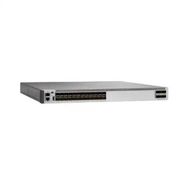
Cisco Catalyst C9500-24Y4C Network Switch for UAE Core and Distribution
The Cisco Catalyst C9500-24Y4C is a fixed 1RU high-performance enterprise switch built for organizations that need dense 25 Gigabit Ethernet aggregation with native 100 Gigabit Ethernet uplinks, deterministic campus-core performance, advanced routing, segmentation, telemetry, and resilient virtualized core designs. With twenty-four SFP28 ports operating at 1G, 10G, or 25G and four QSFP28 ports operating at 40G or 100G, the platform gives UAE enterprises a practical transition path from established 1/10G fiber networks to 25G server, distribution, and campus interconnects without immediately moving to a larger modular chassis.
Best fit: enterprise campus core, distribution, collapsed core, fiber aggregation, resilient headquarters, and high-capacity branch or facility backbones.
Key reason to choose it: 24 × 1/10/25G SFP28 plus 4 × 40/100G QSFP28 in a compact 1RU platform, backed by Cisco IOS XE and StackWise Virtual.
Each front-panel SFP28 interface can support 1G, 10G, or 25G Ethernet according to optic, cabling, software, and design requirements.
Native 40G or 100G uplinks make the chassis suitable for dual-core connections, high-speed inter-building trunks, or data-center-facing aggregation.
Cisco specifies up to 2.0 Tbps of switching capacity for the C9500-24Y4C, enabling high-throughput aggregation in a compact fixed form factor.
Up to one billion packets per second supports latency-sensitive and packet-intensive campus, services, security, voice, video, and application traffic.
What the Cisco C9500-24Y4C is designed to do
The C9500-24Y4C belongs to Cisco’s Catalyst 9500 high-performance family, a fixed enterprise switching platform intended primarily for campus core and distribution roles. The model is especially useful when a network has outgrown 10G aggregation but does not yet require the port density, chassis scale, or operational footprint of a modular core. Its combination of twenty-four multi-rate SFP28 interfaces and four high-speed QSFP28 uplinks lets architects build a compact aggregation layer in which existing 1G and 10G fiber attachments can coexist with newer 25G links. That matters during staged refresh projects because network teams can migrate access stacks, server zones, wireless aggregation, security appliances, and building distribution nodes according to business priorities instead of replacing every optic and endpoint at once.
In a typical UAE enterprise campus, two C9500-24Y4C switches can be deployed as a resilient distribution or collapsed-core pair. Access switches connect over redundant 10G or 25G fiber, while 40G or 100G interfaces provide high-capacity interconnection, upstream, or service-block connectivity. Cisco StackWise Virtual can pair two supported Catalyst 9500 high-performance switches into a single logical system for simplified control-plane operation and multichassis EtherChannel designs. This architecture is attractive for headquarters, universities, healthcare facilities, government environments, hospitality campuses, logistics sites, financial offices, and multi-building industrial estates where maintenance windows are difficult and path redundancy is a primary design requirement.
The platform is also relevant when the switch must operate as a Layer 3 aggregation boundary. Cisco IOS XE provides the operating environment for routing, security, QoS, automation, telemetry, programmability, and lifecycle management. Exact feature availability depends on the selected Network Essentials or Network Advantage tier and the associated Catalyst Software Subscription or Cisco DNA subscription. FourTeck therefore treats the hardware, optics, software tier, support coverage, power configuration, and deployment topology as one engineered bill of materials rather than treating the chassis alone as the complete solution.
Port architecture: 24 × SFP28 plus 4 × QSFP28
1/10/25G SFP28 interfaces
The twenty-four SFP28 ports are the main reason many network teams select this model. SFP28 preserves the familiar small-form-factor pluggable operational model while extending interface speed to 25 Gigabit Ethernet. A migration can therefore be designed around actual link requirements: 1G for legacy fiber handoffs, 10G for existing access or server connections, and 25G for newer distribution uplinks, high-capacity security zones, virtualization hosts, storage-adjacent traffic, or modern access-layer aggregation.
Port speed flexibility should never be interpreted as universal optic compatibility. The exact Cisco-supported optic or cable, fiber type, connector, wavelength, distance, forward-error-correction behavior, and IOS XE release must be checked during design. For a UAE rollout, the bill of materials should identify each link by endpoint type, required speed, fiber plant, strand count, patching, route length, and redundancy path so that the correct transceiver is selected before installation.
40/100G QSFP28 interfaces
Four QSFP28 ports provide high-bandwidth northbound or peer connectivity. In a campus design these interfaces can be used for 40G or 100G uplinks toward a core, a second C9500 peer, a data-center edge, a services block, or another high-capacity aggregation domain. They are particularly valuable when twenty-four downstream 10G or 25G connections would otherwise create an uplink bottleneck.
A common design approach is to reserve two 100G ports for redundant upstream paths and use the remaining ports according to the high-availability architecture. However, the right allocation depends on whether the switches operate independently, as a StackWise Virtual pair, or inside a broader routed campus. StackWise Virtual links can use supported high-performance switch interfaces, and dual-active detection must be planned so that failure modes are deterministic rather than assumed.
UADP 3.0 and high-performance forwarding architecture
Cisco positions the C9500-24Y4C as a high-performance Catalyst 9500 model based on the UADP 3.0 ASIC architecture. For the network architect, the value of this architecture is not simply a headline packet rate. Campus cores must perform multiple functions simultaneously: switching, routing, policy enforcement, classification, QoS, telemetry, multicast handling, segmentation, and resilience. Hardware-assisted forwarding helps the platform process these services at scale while Cisco IOS XE provides the operational and programmability layer above the forwarding hardware.
The model is specified with up to 2 Tbps switching capacity and up to 1 Bpps forwarding. Those figures describe the platform ceiling, not a guarantee that every design can consume every port at maximum line rate under every combination of features and packet sizes. Proper sizing still considers traffic patterns, oversubscription, east-west versus north-south flows, multicast replication, access-control requirements, telemetry, routing-table scale, and the number of failure paths that may concentrate traffic onto fewer interfaces. In a resilient design, capacity planning should model the N-1 state. If one uplink, one port-channel member, one switch, or one service path fails, the surviving links should still carry the expected peak load without unacceptable congestion.
The practical benefit of C9500-24Y4C is therefore architectural headroom. A legacy distribution layer based on multiple 10G trunks can be consolidated into fewer 25G and 100G paths while maintaining a familiar Catalyst operational model. This reduces the number of parallel links required for bandwidth, makes QoS policies easier to reason about, and creates a stronger foundation for high-density Wi-Fi access, IP surveillance aggregation, virtualization, cloud access, collaboration, and distributed application traffic across large UAE campuses.
Core and distribution deployment patterns
Collapsed campus core
For medium and large sites that do not require a separate core tier, a pair of C9500-24Y4C switches can combine distribution and core functions. Access-layer uplinks terminate directly on the pair while firewalls, WAN routers, data-center switches, wireless controllers, and shared services connect at high speed. The resulting design reduces device count while retaining routed segmentation and redundant uplink choices.
Building distribution
In a multi-building campus, each C9500-24Y4C can aggregate multiple access stacks over 10G or 25G fiber and connect toward a central core over 40G or 100G. This model is appropriate where local traffic must be aggregated efficiently before traversing inter-building fiber, and where maintenance or cable failures require dual-homed access-layer connectivity.
Services aggregation
The switch can aggregate links toward firewalls, application-delivery systems, WAN edge devices, secure web gateways, network services, or data-center distribution. Twenty-five-gigabit interfaces are useful when appliances exceed 10G but do not justify 100G per connection, while 100G interfaces provide high-capacity trunks to adjacent switching domains.
Routed access or fabric edge aggregation
Organizations moving from large Layer 2 fault domains toward routed access can use the C9500-24Y4C as the aggregation point for routed uplinks. This can simplify failure containment, improve convergence behavior, and make route-based policy easier to automate. Feature and license requirements should be mapped before the architecture is finalized.
StackWise Virtual and high availability
Cisco StackWise Virtual is one of the most important design capabilities for organizations evaluating the C9500-24Y4C as a resilient core or distribution pair. It virtualizes two physical switches into a single logical switching system, simplifying the control and management model and enabling multichassis EtherChannel connectivity from downstream or upstream devices. On the C9500 high-performance family, supported interfaces can be assigned as StackWise Virtual links, and separate dual-active detection is used to protect against split-control conditions.
The design should reserve adequate bandwidth for the StackWise Virtual link based on anticipated cross-chassis traffic. A common mistake is to size only normal-state traffic. If access switch A is physically connected to both chassis but most flows normally remain local, a failure can force additional traffic over the virtual link. Similar concentration occurs during uplink loss or maintenance. FourTeck therefore sizes the SVL, uplink port channels, and downstream EtherChannels using expected failure-state traffic rather than simply multiplying nominal interface speeds.
Dual-active detection also deserves deliberate physical separation. It should not share the same single point of failure as the virtual link it protects. Depending on the design and supported configuration, interfaces should be allocated so that DAD remains available if the primary virtual link path is disrupted. Network teams should validate the exact Cisco IOS XE release, supported SVL interface types, optics, and configuration guidance before deployment. Cisco documentation supports StackWise Virtual on the C9500-24Y4C, with high-performance models able to establish virtual links using supported 10G, 25G, 40G, or 100G connectivity.
StackWise Virtual is not mandatory. Some enterprises prefer a routed pair using first-hop redundancy, dynamic routing, and independent control planes because it reduces shared-state coupling. The best architecture depends on operational skills, convergence targets, maintenance procedures, downstream EtherChannel requirements, failure-domain philosophy, and whether the campus is moving toward routed access or a software-defined fabric.
Layer 2 switching and campus segmentation
At the distribution layer, Layer 2 behavior must be intentionally constrained. The C9500-24Y4C can participate in VLAN and spanning-tree designs, but modern campuses should avoid extending broadcast domains farther than application and operational requirements demand. Where access switches must remain Layer 2, use deterministic root placement, explicit trunk VLAN allow lists, EtherChannel consistency, loop-protection features, storm-control policies, and clear failure-domain boundaries. Where practical, route at the access or distribution boundary and use the C9500 as a Layer 3 aggregation device.
Segmentation is not only about VLAN separation. Enterprises increasingly need user, voice, IoT, camera, building-management, guest, contractor, OT, and server traffic to remain logically isolated even when it shares the same physical switching infrastructure. Cisco Catalyst platforms support policy mechanisms that can be combined with routing, VRF design, access control, identity services, and Cisco TrustSec capabilities depending on license and architecture. The correct segmentation model should be defined from business policy first, then translated into VLANs, VRFs, security groups, route leaking, firewall zones, or software-defined policy constructs.
For UAE organizations handling regulated workloads, the core should make traffic paths auditable. A design document should show where segmentation is enforced, where inter-segment inspection occurs, which prefixes are advertised between zones, and how privileged management traffic is separated. This is particularly important in mixed IT and OT sites, hospitals, hotels, schools, logistics facilities, and large commercial buildings where non-user devices can outnumber conventional employee endpoints.
Layer 3 routing for enterprise backbones
The C9500-24Y4C is frequently selected because the distribution layer needs more than basic inter-VLAN routing. Cisco IOS XE supports enterprise routing features across the Catalyst 9500 family, with exact availability depending on the software license tier. Typical campus designs use static routes for small controlled environments, OSPF or IS-IS for scalable internal routing, and BGP where policy control, WAN integration, data-center connectivity, cloud connectivity, or large routed domains require it. Network Advantage is generally the tier considered when advanced routing, segmentation, multicast, scale, and high-availability capabilities are required.
Route design should minimize dependency on spanning tree for convergence. Redundant point-to-point Layer 3 links or routed port channels allow dynamic protocols to detect failures and reconverge according to defined timers and metrics. Equal-cost multipath can use multiple available paths, while summarization limits routing-table growth and reduces the scope of topology changes. At campus boundaries, route filtering should be explicit so that an accidental advertisement from one building or tenant cannot destabilize the entire backbone.
IPv6 planning should be performed alongside IPv4 rather than postponed indefinitely. Even where production applications remain predominantly IPv4, management systems, operating systems, cloud services, and security platforms increasingly interact with IPv6. The core design should define address allocation, first-hop behavior, routing policy, ACL strategy, monitoring, and security controls for both protocol families. Dual-stack operation should be tested under failure and upgrade scenarios, not only under normal forwarding.
For multicast-heavy environments such as IPTV, live media distribution, market data, large digital-signage networks, or some OT systems, routing and replication behavior must be sized specifically. Multicast can change traffic concentration dramatically because a single source stream may be replicated toward many downstream ports. The design should document PIM mode, rendezvous-point strategy where applicable, receiver distribution, expected group scale, and whether QoS must protect critical multicast from bulk unicast flows.
QoS for voice, video, business applications, and congestion control
A 25G or 100G backbone can still experience congestion. Higher link speed reduces the probability of sustained contention, but bursty storage transfers, backups, software distribution, video, surveillance, cloud synchronization, and east-west application traffic can converge on the same uplink. QoS therefore remains a core design requirement. The first step is to define a trust boundary: decide where markings are accepted, rewritten, or classified. Endpoints should not be allowed to assign themselves premium service without policy unless they are explicitly trusted.
Traffic classes should reflect operational goals rather than copy an oversized template. Real-time voice generally needs strict latency and jitter protection, interactive video needs assured bandwidth, routing and control traffic need protection from data-plane storms, business-critical applications may require preferred service, and bulk transfers can use remaining capacity. The C9500 distribution layer must preserve intended DSCP behavior across port channels, routed interfaces, service blocks, and WAN handoffs.
Capacity planning and QoS planning must be combined. If a 100G uplink normally carries 30G but can rise to 70G after a peer failure, congestion policy should be tested at the N-1 utilization point. Monitoring should capture queue drops and microbursts, not only five-minute interface averages. A link can show low average utilization and still drop latency-sensitive traffic during sub-second bursts. Cisco telemetry and interface statistics can be integrated into the operations platform so that queue behavior is visible before users report poor voice or application performance.
Security architecture at the switching core
A campus core is not a firewall replacement, but it is an important enforcement and visibility point. The C9500-24Y4C can support access-control, segmentation, control-plane protection, secure management, telemetry, and identity-driven architectures when configured with the appropriate software capabilities. The security objective is to reduce implicit trust while keeping forwarding predictable. Infrastructure interfaces should allow only required protocols, management access should originate from controlled subnets, unused services should be disabled, and routing adjacencies should be authenticated where supported and appropriate.
Control Plane Policing protects the CPU from excessive traffic directed at the switch itself. This matters because even a device with large forwarding capacity can be affected if malicious or accidental traffic overwhelms control-plane processing. Network teams should understand Cisco’s default policies before applying changes; aggressive custom policing can cause routing, discovery, or management protocols to fail under stress. Changes must be tested against expected traffic and logged so that operations teams can distinguish a security drop from a physical-link or protocol failure.
Segmentation should coordinate with the firewall architecture. If two business zones are meant to be inspected, the routing design must not accidentally create a local Layer 3 shortcut around the firewall. Conversely, traffic that does not require inspection should not be forced through a centralized firewall merely because the network lacks a clear segmentation model. The core design should document which inter-VRF or inter-VLAN flows are routed locally, which are redirected to security appliances, and how asymmetric routing is prevented.
For organizations building a broader security refresh, FourTeck can align Catalyst switching with the firewall and infrastructure architecture through the Firewall Dubai FourTeck platform, while overall UAE networking and procurement requirements can be coordinated through FourTeck UAE.
Cisco IOS XE, programmability, and operational consistency
Cisco IOS XE is central to the operating model of the C9500-24Y4C. Enterprise network teams benefit from a common software family across much of the Catalyst 9000 portfolio, reducing the operational gap between access, distribution, and core. The platform supports traditional CLI workflows while also enabling structured automation, APIs, model-driven telemetry, and controller-based management. This means a company can adopt automation incrementally: start with standardized configuration templates and version-controlled backups, then move toward API-driven provisioning and continuous compliance as operational maturity grows.
Automation should not simply reproduce manual configuration faster. A better goal is to define intent and validate outcome. For example, a new building distribution switch can be provisioned with interface standards, routing policy, NTP, AAA, logging, telemetry, SNMP where required, syslog destinations, management VRF, banners, role-based access, and software compliance checks. The automation pipeline should then verify neighbor relationships, port-channel state, route counts, latency, and redundancy. This reduces configuration drift and makes changes easier to audit.
Model-driven telemetry provides higher-frequency, structured operational data compared with relying exclusively on periodic command-line polling. It can be used to observe interface counters, queue behavior, environmental status, routing state, and platform health. The receiving analytics system determines how valuable that data becomes. Network teams should avoid collecting everything without a retention plan; instead they should identify the metrics needed for capacity, incident detection, service-level reporting, and forensic troubleshooting.
Software lifecycle control is equally important. Before an IOS XE upgrade, check Cisco release notes, recommended releases, field notices, security advisories, optic compatibility, and feature caveats for the exact platform and license. Lab or pilot validation should reproduce the production topology as closely as practical, particularly StackWise Virtual, routing adjacencies, authentication, multicast, telemetry, and any features that depend on controller integration.
Licensing: Network Essentials, Network Advantage, and subscriptions
Cisco Catalyst 9500 procurement includes both the hardware/software base tier and a subscription choice. Current Cisco ordering guidance lists C9500-24Y4C variants with Network Essentials or Network Advantage, and requires a corresponding Catalyst Software Subscription or Cisco DNA subscription for new orders. Subscription terms are offered in multi-year options such as three, five, or seven years. Because ordering rules and software packaging can change, the exact configuration should always be validated in Cisco Commerce or through the authorized supply channel at quotation time.
| Decision area | Essentials-oriented design | Advantage-oriented design |
|---|---|---|
| Typical requirement | Foundational switching, routing, automation, visibility, and security | Advanced routing, segmentation, multicast, policy, scale, and assurance requirements |
| Best procurement practice | Confirm every required feature against the current Cisco feature matrix before ordering | Map advanced features and controller integrations to the correct perpetual and subscription tiers |
| Operational consideration | Avoid paying for features that will not be deployed | Avoid under-licensing a core design that depends on advanced routing or segmentation |
The licensing conversation should happen during architecture design, not after the equipment arrives. If the network requires BGP policy, advanced multicast, large-scale segmentation, software-defined access, assurance, or specialized security capabilities, those requirements should be written into the bill of materials and tested against the current Cisco feature matrix. Similarly, if a simpler routed campus can meet the business requirement with an Essentials-oriented configuration, the procurement team should not assume the higher tier is automatically necessary merely because the switch sits in a core position.
Cisco licensing has evolved over time, including Smart Licensing and Smart Licensing Using Policy. Organizations with existing Cisco Smart Accounts should confirm account ownership, virtual-account structure, entitlement visibility, and operational responsibilities before deployment. This avoids a common implementation problem in which the hardware is installed successfully but the network team cannot complete registration, entitlement reporting, controller onboarding, or support processes because the purchasing entity and operational Smart Account were not aligned.
Optics and cabling design for 1G, 10G, 25G, 40G, and 100G
Transceiver selection is a substantial part of a C9500-24Y4C deployment. A chassis quote without a link-by-link optic schedule is incomplete because the network’s real cost, distance capability, and reliability depend on the optical layer. Each connection should be documented with speed, connector, fiber type, wavelength, maximum path length, patch panels, splices, and the optic or DAC/AOC required at both ends. The remote device must support the same Ethernet standard and compatible optical characteristics.
For short in-rack or adjacent-rack links, direct-attach or active optical cabling may be practical when supported. For building or campus fiber, multimode and single-mode choices depend on distance, installed plant, and future roadmap. A network that is moving to 25G should verify whether existing multimode infrastructure supports the target distance and optic type; a network moving to 100G should check lane architecture, connector requirements, patching, cleanliness, and optical budget. The cheapest transceiver on a spreadsheet can become the most expensive option if the installed fiber cannot support it reliably.
Forward Error Correction is particularly relevant at 25G and 100G. The switch and remote endpoint must negotiate or be configured for compatible FEC behavior. Cisco release notes contain model-specific guidance and restrictions, so FEC should not be changed casually to make a marginal link appear functional. Excessive errors often indicate an optical, cabling, polarity, cleanliness, or compatibility issue that should be corrected rather than hidden.
The optic plan should include spares. Critical UAE sites commonly maintain spare transceivers for the speeds and reaches used in the core, because a core optic failure can be more disruptive than a chassis component failure if no compatible part is locally available. Spares should be labeled, stored cleanly, tracked by part number, and periodically checked against the live design so that the shelf stock remains usable after network upgrades.
Physical installation, power, and airflow
The C9500-24Y4C is a 1RU switch. Cisco hardware documentation lists physical dimensions of approximately 1.73 × 17.5 × 18.0 inches and a chassis weight of about 20.99 lb when configured with two power supplies and the built-in fan arrangement. Its relatively shallow depth compared with some high-density core platforms can simplify deployment in enterprise racks, but installation should still verify rail compatibility, front and rear clearance, cable bend radius, fiber management, PDU access, and serviceability.
The platform provides two power-supply slots and supports redundant power configurations with compatible AC or DC supplies according to the model. Cisco documentation lists a 90–264 VAC input range for the C9500-24Y4C. The exact power-supply part number should be selected from the current Cisco ordering guide; high-performance C9500 models use different PSU families from some earlier C9500 variants. Redundant supplies should ideally connect to separate PDUs and separate UPS paths when the facility electrical architecture supports it. Installing two supplies into the same single PDU does not eliminate the upstream electrical single point of failure.
Airflow must match the rack and data-room design. Fan trays and power supplies are field-replaceable components, and blanking requirements must be respected because empty slots can disturb designed airflow. In UAE environments, cooling margin is particularly important for telecom rooms, warehouses, remote facilities, and mixed-use buildings where ambient temperature may fluctuate more than in a tightly controlled data center. The switch should operate within Cisco’s environmental limits, with rack inlet temperature monitored rather than inferred from room thermostat readings.
Power and cooling calculations should use worst-case planning values from current Cisco documentation, not informal averages from a lightly loaded switch. Actual draw varies with optic population, port utilization, fan speed, environmental conditions, and configuration. The electrical engineer or facilities team should size UPS, PDU, circuit, generator, and cooling capacity for the designed deployment and its redundancy mode.
Sizing methodology for a C9500-24Y4C deployment
1. Count physical attachments
List every access stack, firewall, WAN router, server switch, wireless controller, service appliance, peer switch, and management connection. Record whether each endpoint needs one link, a port channel, or dual-homing. Port count must be calculated for normal and migration states because temporary coexistence can consume additional interfaces.
2. Assign required speed
Do not assign 25G or 100G simply because the switch supports it. Use traffic measurements, growth forecasts, application requirements, failure-state concentration, and endpoint capability. Some links remain well served by 10G, while high-density access, storage-adjacent, firewall, or virtualization paths may justify 25G or 100G.
3. Model N-1 capacity
Remove one switch, one uplink member, or one upstream path from the capacity model. Determine whether the surviving links can carry peak traffic and whether QoS still protects critical applications. High availability without surviving capacity merely converts a hard outage into severe congestion.
4. Size routes and policy
Estimate IPv4 and IPv6 routes, hosts, ACLs, multicast groups, VRFs, VLANs, telemetry flows, and policy scale. Cisco platform limits vary by model, software release, template, and feature combination, so current documentation must be checked against the actual design rather than relying on family-level marketing values.
5. Validate optic reach
Measure or document fiber-path distance and type for every link. Include patch panels and intermediate cross-connects. Select optics only after confirming remote-platform support, and reserve budget for optical testing or cleaning if the existing fiber plant is being reused for higher speeds.
6. Build growth headroom
Keep spare ports and uplink capacity for planned buildings, new Wi-Fi deployments, additional firewalls, cloud interconnects, or server expansion. A design that consumes every SFP28 and QSFP28 port on day one may force another hardware project during the first growth cycle.
Migration from 10G distribution to 25G/100G
The multi-rate interfaces on the C9500-24Y4C are valuable during migration because the new core can support existing 10G links while selected paths are upgraded to 25G. A low-risk migration starts with discovery. Export the current configuration, topology, VLAN database, routing table, spanning-tree state, port-channel membership, transceiver inventory, interface utilization, QoS policy, ACLs, multicast configuration, first-hop redundancy, logging, NTP, AAA, SNMP or telemetry, and software versions. Capture enough information to reproduce both intended design and undocumented dependencies.
Next, classify links into migration groups. Infrastructure links such as core-to-firewall, core-to-WAN, and core-to-data-center often deserve separate maintenance steps because a problem can affect the entire site. Access-layer uplinks can be migrated building by building. If the old and new cores must coexist, define temporary routing metrics, spanning-tree root placement, gateway ownership, and VLAN boundaries so that traffic does not oscillate between systems. Temporary designs should be documented and removed after cutover; otherwise migration exceptions become permanent technical debt.
Before production cutover, validate optics, interface speed, FEC, port channels, routing neighbors, MTU, DHCP relay, DNS reachability, authentication, monitoring, syslog, NTP, and management access. Test the failure scenarios that matter most: disconnect one uplink, reload one chassis, remove one port-channel member, break one routing adjacency, and confirm that traffic follows the intended backup path. For StackWise Virtual, validate virtual-link and dual-active behavior according to Cisco guidance.
A rollback plan should specify exactly what triggers rollback, which commands or cable moves restore the original state, how long the decision window remains open, and who has authority to call the rollback. The best migration plans minimize simultaneous variables. Changing the core hardware, IP addressing, routing protocol, segmentation model, firewall policy, and monitoring platform in one maintenance window can make troubleshooting unnecessarily complex.
Monitoring, telemetry, and troubleshooting readiness
Core-switch monitoring should answer three questions quickly: Is the hardware healthy? Is the control plane stable? Is the data plane delivering the expected service? Hardware monitoring covers temperature, fans, power supplies, optics, interface errors, and platform alarms. Control-plane monitoring covers CPU, routing neighbors, spanning tree where used, StackWise Virtual state, authentication, configuration changes, and protocol events. Data-plane monitoring covers link utilization, queue drops, latency where measured, packet loss, errors, discards, and traffic distribution across port-channel members.
Thresholds should be meaningful. A 100G interface at 60 percent utilization is not automatically a problem, while a 10G interface averaging 15 percent could still experience burst drops. Alerting should distinguish persistent conditions from transient changes and should include enough context for the operations team to act. Environmental alerts need rack and site identity, optic alerts need interface and remote endpoint, and routing alerts need neighbor and affected prefix context.
Operational runbooks should contain the verification commands and escalation path for common incidents. Examples include loss of a StackWise Virtual member, an optic reporting high receive power or low transmit power, a port channel carrying traffic on only one member, a BGP or OSPF neighbor flap, high control-plane CPU, repeated interface errors, or unexpected MAC movement. The runbook should also define when a problem is likely physical, configuration-related, software-related, or dependent on an adjacent firewall, WAN, or server platform.
FourTeck can integrate the switching layer with broader UAE infrastructure support and operational services through FourTeck IT Services UAE, including deployment planning, structured troubleshooting, monitoring alignment, and lifecycle support around the surrounding network environment.
Integration with firewalls, WAN, servers, and wireless infrastructure
A core switch should be sized as part of the end-to-end architecture. For firewall integration, identify whether the firewall connects using routed point-to-point links, a Layer 2 transit segment, an EtherChannel, or separate inside, outside, DMZ, and service-zone interfaces. A modern firewall may support 10G, 25G, 40G, or 100G interfaces, but effective throughput depends on enabled inspection services and traffic profile. The switch link should be chosen based on realistic inspected throughput, not only the appliance’s raw interface speed.
WAN and SD-WAN edge devices often require less bandwidth than the core can provide, but route policy is more important than interface speed. Define default-route behavior, local internet breakout, cloud routes, branch summarization, route redistribution, and failure preference. If two WAN edges are used, ensure that the core and WAN routing policies converge consistently and do not create asymmetric paths through stateful security appliances.
Server and data-center integration can quickly justify 25G. Virtualization hosts commonly aggregate many workloads, and modern storage or backup traffic can saturate 10G. The C9500-24Y4C can serve as a campus-facing aggregation point, but it should not automatically replace a purpose-built data-center leaf-spine fabric. Requirements such as storage behavior, ultra-low latency, VXLAN data-center fabrics, massive east-west throughput, or specialized buffer needs may indicate a different platform family. Architecture should follow workload requirements rather than forcing one switch to perform every role.
Wireless infrastructure is another major bandwidth driver. Wi-Fi 6, Wi-Fi 6E, and newer high-density access deployments can increase aggregate traffic from access switches even when individual users are bursty. Distribution links that were comfortable at 10G may become constrained after access switch and AP refreshes. A staged move to 25G access-to-distribution uplinks can create additional margin without changing every downstream client-facing component.
Where server-room modernization is part of the same project, customers can also review adjacent infrastructure options through FourTeck Server Dubai so switch uplinks, compute density, rack power, and network capacity are planned together rather than as separate procurement decisions.
UAE deployment considerations: Dubai, Abu Dhabi, Sharjah, and regional sites
Enterprise switching projects in the UAE often span more than one type of facility. A headquarters data room in Dubai may have controlled cooling and redundant UPS, while a warehouse, retail site, school, clinic, hotel, or industrial office may rely on smaller telecom rooms with different environmental and maintenance constraints. The C9500-24Y4C design should therefore be standardized at the architecture level while allowing site-specific power, optics, rack, fiber, and support details.
Local stock and lead time matter when a platform is used as a core. Procurement should identify whether the project needs complete chassis redundancy, spare power supplies, spare fan trays, spare SFP28 or QSFP28 optics, console accessories, and locally available replacement parts. A single spare optic may have more operational value than an unused chassis option if that optic is the only part that can restore a 100G building interconnect. Conversely, a mission-critical site may justify a complete cold spare or rapid hardware support coverage depending on business impact and recovery objectives.
Structured cabling also needs local validation. Existing building fiber may have undocumented joins, contaminated connectors, mixed fiber grades, or patch paths that were acceptable at 1G/10G but become problematic at 25G/100G. Certification and optical testing before cutover can prevent difficult post-installation errors. Labeling should identify switch, interface, panel, fiber pair, destination, and path redundancy. Physically diverse links should not unknowingly share the same tray, conduit, riser, or intermediate cabinet if the design assumes route diversity.
Support arrangements should match business hours and site criticality. A 24×7 operation such as hospitality, healthcare, logistics, or financial services may require different escalation and spare strategies from a standard office campus. Cisco support option, integrator response, remote-access process, change approvals, and after-hours site access should be decided before an incident rather than while the core is impaired.
For organizations that operate beyond the UAE, FourTeck can align core-switch standards with broader regional deployment requirements through FourTeck Africa, helping multisite teams keep BOM logic, configuration standards, and operational documentation consistent across locations.
When the C9500-24Y4C is the right model — and when it is not
The C9500-24Y4C is a strong fit when the primary requirement is a compact fixed enterprise core or distribution switch with up to twenty-four multi-rate 1/10/25G fiber interfaces and four 40/100G uplinks. It is especially attractive when an organization is migrating from 10G to 25G in stages, wants native 100G uplinks, needs Cisco IOS XE operational consistency, or plans a resilient two-switch design with StackWise Virtual or routed high availability.
It may not be the correct choice when port density is much higher. If the design needs far more than twenty-four 25G ports, a higher-density C9500 model or a different platform may reduce chassis count and complexity. If the network requires 400G interfaces, very large route scale, or newer silicon capabilities beyond this generation, Catalyst 9500X or another Cisco family may be more appropriate. If the requirement is predominantly copper access with PoE for users, phones, cameras, or access points, an access-layer Catalyst model is usually the better fit because the C9500-24Y4C is a fiber-focused core/distribution platform.
It may also be oversized for a small office that has only a few 1G or 10G uplinks and simple routing. Buying a high-performance core without a traffic, growth, or resilience requirement increases cost and operational complexity without improving user experience. Conversely, under-sizing a campus because current utilization is low can force a second refresh when Wi-Fi, surveillance, cloud, virtualization, and application traffic grow.
The correct selection is determined by architecture, not by model popularity. Port speed, optic reach, route scale, policy requirements, licensing, redundancy, support, rack power, future growth, and the skill set of the operations team should all be part of the choice.
Technical specification summary for quotation planning
| Product | Cisco Catalyst C9500-24Y4C Network Switch |
| Platform role | High-performance fixed enterprise campus core and distribution |
| Primary interfaces | 24 × SFP28 supporting 1/10/25 Gigabit Ethernet |
| High-speed interfaces | 4 × QSFP28 supporting 40/100 Gigabit Ethernet |
| ASIC family | Cisco UADP 3.0 architecture |
| Switching capacity | Up to 2.0 Tbps |
| Forwarding rate | Up to 1 Bpps |
| Form factor | 1RU fixed switch |
| Approximate dimensions | 1.73 × 17.5 × 18.0 in. / 4.4 × 44.5 × 45.7 cm |
| Approximate configured weight | 20.99 lb / 9.52 kg with two power supplies and fan configuration per Cisco hardware documentation |
| Power architecture | Two power-supply slots; compatible redundant AC or DC options depend on current ordering matrix |
| AC input range | 90–264 VAC for C9500-24Y4C per Cisco hardware installation documentation |
| High availability | Supports Cisco StackWise Virtual and dual-active detection when designed according to supported release and interface guidance |
| Operating system | Cisco IOS XE |
| License choices | Network Essentials or Network Advantage with corresponding current Cisco subscription selection |
Specification and ordering details can change with Cisco software and commerce updates. Final quotation should validate the exact hardware PID, license tier, subscription term, power supplies, airflow direction, transceivers, cable types, software release, and support option against the current Cisco ordering and compatibility documentation.
Recommended implementation sequence
- Discovery and requirements: document topology, current utilization, critical applications, outage constraints, route scale, VLAN and VRF structure, security zones, multicast, QoS, optics, rack environment, UPS capacity, and growth targets.
- High-level design: decide whether the C9500 pair will operate as independent routed devices or StackWise Virtual; define uplink speeds, port channels, failure domains, routing protocols, segmentation, firewall paths, and management architecture.
- Bill of materials: choose C9500-24Y4C license variant, subscription term, redundant PSU configuration, optics, DAC/AOC where applicable, patching, spare transceivers, console requirements, support coverage, and any integration services.
- Low-level design: assign interface numbers, IP addressing, VLANs, VRFs, routing neighbors, port-channel IDs, QoS classes, ACLs, management services, telemetry, logging, authentication, NTP, DNS, and software version.
- Staging: install the intended IOS XE release, confirm licensing state, apply base configuration, test optics, verify redundancy, validate management access, and collect a known-good baseline before shipping to site.
- Site installation: mount the switch, connect independent power feeds where designed, verify airflow, clean and patch fiber, label every connection, confirm receive/transmit optical levels, and validate physical redundancy.
- Migration: move links in controlled groups, validate routing and application reachability after each group, monitor errors and congestion, and preserve a defined rollback path until the acceptance criteria are met.
- Handover: provide as-built diagrams, final configurations, software and license records, optic inventory, support details, backups, monitoring thresholds, runbooks, and a list of known design decisions for operations teams.
Frequently asked technical questions
Does the C9500-24Y4C support both 10G and 25G on the same chassis?
Yes. Its twenty-four SFP28 ports support 1G, 10G, and 25G Ethernet, allowing mixed-speed migration. Each link must use a compatible optic or cable and supported remote endpoint. Port configuration, FEC, and software compatibility should be validated for the exact connection.
How many native 100G ports are available?
The switch provides four QSFP28 interfaces that support 40G or 100G Ethernet. These are commonly used for core, upstream, peer, or services-block connectivity. The final allocation depends on whether some of these links are reserved for redundancy or StackWise Virtual functions.
Can two C9500-24Y4C switches operate as one logical system?
Cisco supports StackWise Virtual on the C9500-24Y4C. Two switches can be virtualized into one logical system with StackWise Virtual links and dual-active detection. The exact design, software release, interfaces, and failure tests should follow current Cisco configuration guidance.
Is Network Advantage always required?
No. The required tier depends on the features the design uses. Network Essentials covers foundational capabilities, while Network Advantage adds advanced routing, segmentation, multicast, scale, and security capabilities. The feature matrix for the intended IOS XE release should be checked before ordering.
Can this switch replace a data-center leaf switch?
Sometimes it can serve as a campus-facing aggregation device for servers or a small server room, but it should not automatically replace a purpose-built data-center platform. Large-scale VXLAN fabrics, specialized buffering, ultra-low-latency workloads, storage requirements, or 400G growth may point to a different Cisco family.
Does the switch include redundant power by default?
The chassis has two power-supply slots, but the ordered configuration determines how many supplies are included. A production core typically uses two compatible power supplies connected to independent upstream power paths where available. The quote should explicitly show the redundant PSU selection.
What should be included with a UAE quotation?
At minimum: exact switch PID, Essentials or Advantage tier, subscription term, two power supplies if redundancy is required, power cords, SFP28/QSFP28 optics or cables for each link, spare optics, support coverage, implementation scope, software version plan, and a topology describing how the switch will be used.
Why use 25G instead of adding more 10G links?
Twenty-five-gigabit Ethernet provides 2.5 times the line rate of 10G per lane while retaining the SFP28 form factor. It can reduce the number of parallel links needed for aggregation, simplify cabling and port-channel design, and create more headroom for modern access, server, security, and wireless traffic. The endpoint and fiber plant must support the chosen 25G implementation.
Why procure the C9500-24Y4C through an engineered solution approach
The largest risk in core-switch purchasing is treating the chassis as a standalone commodity. Two quotations can show the same model number but represent very different production readiness. One may include only the base chassis and a minimum software term; another may include redundant power, the correct airflow, supported optics, spare transceivers, proper subscription tier, installation, migration, documentation, and support. Comparing only chassis price can therefore hide the cost of making the network operational.
FourTeck’s solution approach starts with the traffic and topology requirement. If the customer needs twelve 10G access stacks today and expects six more 25G uplinks within two years, that growth pattern affects port reservation. If the firewall pair has 25G interfaces, the core design must decide whether each firewall uses separate routed links or port channels. If two 100G uplinks connect to a central core, the optic reach and physical route diversity must be checked. If StackWise Virtual is planned, interfaces for SVL and DAD must be reserved before the remaining port budget is calculated.
The result is a bill of materials that maps every component to a design function. This makes approval easier for technical and procurement teams because optional items are distinguishable from required items. It also reduces surprises at installation. The objective is not merely to deliver a Cisco box; it is to deliver a switch configuration that can be powered, licensed, patched, monitored, supported, and migrated into the existing UAE environment.
Organizations that need cross-border product and integration coordination can also reference FourTeck Global for broader enterprise sourcing and technology engagement while retaining a UAE-focused implementation plan.
Decision recap: choose C9500-24Y4C when these conditions are true
You need up to twenty-four fiber connections that may operate at 1G, 10G, or 25G, and you want a clean migration path without replacing all links at the same time.
You need up to four native 40/100G QSFP28 interfaces for high-speed peer, core, service-block, or upstream connectivity.
A fixed 1RU platform is preferable to a modular chassis because the required density is known and rack space, power, or operational simplicity matters.
You plan to deploy a redundant pair using StackWise Virtual or independent routed high availability and have enough link capacity for N-1 operation.
Your operations team benefits from Cisco IOS XE, Catalyst automation, telemetry, Smart Licensing workflows, and common enterprise switching practices.
You can align hardware, subscription term, support, optics, spares, and software lifecycle into a documented procurement and operations plan.
Quotation input checklist for UAE projects
A precise quotation is faster when the network requirement is described in engineering terms. Send as many of the following details as available; missing items can be resolved during design.
Emirate/city, number of buildings, existing core model, access-switch count, firewall and WAN design, and whether a collapsed core or separate distribution layer is required.
Number of 1G, 10G, 25G, 40G, and 100G links; which links require port channels; and how many spare interfaces should remain after migration.
Fiber type, connector type, approximate link distances, remote device models, installed transceivers, and whether DAC/AOC connections are acceptable for local rack links.
OSPF, BGP, static routing, multicast, VRFs, VLAN count, SD-Access requirements, route scale, inter-VRF policy, and firewall insertion points.
Single or dual chassis, StackWise Virtual preference, independent routing preference, maintenance-window expectations, business recovery target, and acceptable failure-state utilization.
AC or DC requirement, redundant PDU/UPS availability, airflow constraints, desired Cisco support level, local spare requirements, and whether installation and migration services are included.
Final consultation panel: build the switch around the network, not the other way around
The Cisco Catalyst C9500-24Y4C is a compelling platform for UAE enterprises that need dense 25G aggregation, native 100G uplinks, high forwarding performance, resilient two-switch designs, and Cisco IOS XE operations in a compact 1RU footprint. Its value is highest when it is designed as part of the whole campus: access uplinks, firewalls, WAN, server connectivity, optical plant, routing, segmentation, monitoring, licensing, power, and support.
Before ordering, FourTeck can review the existing topology, identify link speeds and optic reaches, calculate normal and failure-state bandwidth, map required software features to the correct license tier, reserve interfaces for StackWise Virtual or routed resilience, and produce a structured bill of materials. This approach helps technical teams avoid under-sized uplinks, missing optics, licensing mismatches, single-PDU redundancy, untested fiber, and migration designs that become difficult to troubleshoot under maintenance-window pressure.
• Required 10G/25G/100G port counts
• Fiber type and approximate distances
• Existing core/access models
• Essentials or Advantage feature needs
• Redundancy, support, and migration scope

Reviews
There are no reviews yet.