
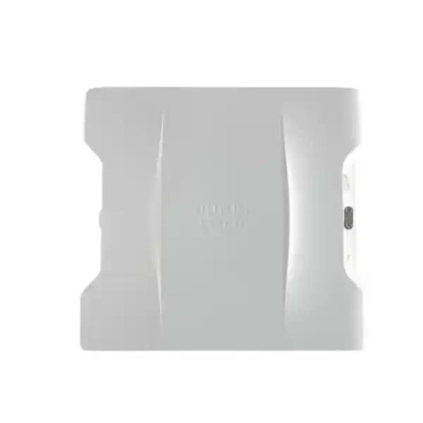
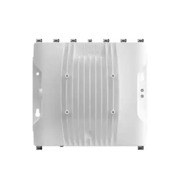
Cisco Catalyst IW9167I Industrial Access Point
The Cisco Catalyst IW9167I is a heavy-duty industrial and outdoor wireless access point designed for organizations that need enterprise-class Wi‑Fi in places where ordinary indoor access points are not physically suitable. Its cast-aluminum enclosure, integrated antennas, IP67 environmental protection, tri-radio architecture, Wi‑Fi 6E capability, multigigabit wired connectivity, SFP support, Bluetooth Low Energy radio and integrated GNSS make it a strong platform for factories, warehouses, logistics yards, ports, energy sites, transport infrastructure, campuses and other operational environments across the UAE.
Choose the IW9167I when you need ruggedized, integrated-antenna Wi‑Fi 6E with 4×4:4 spatial streams, up to 5 Gbps copper Ethernet, an SFP interface supporting up to 10 Gbps, PoE or DC input, and controller-based Cisco enterprise wireless operations. Confirm the exact UAE regulatory domain and permitted 6 GHz operation before ordering and commissioning.
What the Cisco Catalyst IW9167I is designed to solve
Industrial wireless design is not simply an indoor WLAN design moved outside. Production floors introduce metal surfaces, moving machinery, high racking, motors, electrical noise, constantly changing propagation paths and strict availability expectations. Outdoor yards introduce heat, dust, moisture, wind-driven particles, long cable runs, pole mounting, lightning and surge considerations, uncertain line of sight and rapidly changing client locations. Warehouses and logistics hubs introduce handheld terminals, vehicle-mounted terminals, scanners, cameras, voice devices and roaming clients that can move through a large coverage domain without regard for convenient access-point placement. The IW9167I addresses the physical side of this challenge with a rugged enclosure and integrated omnidirectional antennas while preserving the enterprise WLAN behavior expected from Cisco Catalyst wireless infrastructure.
For UAE buyers, the product is especially relevant where wireless equipment must operate in mixed indoor-outdoor industrial estates, distribution centers, airport-related facilities, seaports, oil and gas support environments, utilities, large campuses and manufacturing compounds. The correct design begins by identifying which clients must connect, what applications they run, how fast they move, what latency and availability targets apply, and what wired and power infrastructure exists at each mounting location. Only after these questions are answered should the access-point count, channel plan, mounting height and power method be finalized.
FourTeck positions the IW9167I as an engineering component rather than a standalone coverage gadget. A complete deployment normally includes compatible switching, appropriate PoE power, fiber or copper uplinks, controller software, Cisco licensing, grounding and surge strategy, mounting hardware, validated regulatory-domain selection, structured cabling, environmental sealing and a post-installation RF validation. Organizations that need a broader enterprise network design can also coordinate switching, security, segmentation and infrastructure requirements through FourTeck UAE.
Tri-radio Wi‑Fi 6E architecture and spectrum planning
The IW9167I incorporates radios for 2.4 GHz, 5 GHz and 6 GHz operation. Cisco documents 4×4 uplink and downlink MU-MIMO with four spatial streams for 802.11ax operation across these bands, subject to regional regulatory permissions and supported software configuration. This architecture is important because industrial networks often contain a mixture of legacy clients and newer devices. Some scanners and embedded endpoints may still require 2.4 GHz. Most modern enterprise clients operate efficiently on 5 GHz. Newer Wi‑Fi 6E-capable devices can take advantage of 6 GHz where the band is permitted and the deployment is engineered for it.
The 2.4 GHz band should generally be treated as a compatibility and coverage layer rather than the primary capacity band for a dense industrial design. Its limited non-overlapping channel availability means excessive transmit power or excessive AP density can increase co-channel contention. The 5 GHz band offers much more design flexibility and remains the workhorse for many enterprise WLANs. The 6 GHz band adds substantial spectrum potential for Wi‑Fi 6E clients, but its use must be designed around the local regulatory framework, client support and the propagation characteristics of the environment. Higher-frequency signals typically experience greater attenuation through obstacles, so a 6 GHz capacity layer may require a denser cell plan than a simple 2.4 GHz coverage calculation would suggest.
Cisco specifies 20 MHz operation at 2.4 GHz, 20/40/80 MHz operation on the 5 GHz radio and support for 20/40/80/160 MHz channels on the 6 GHz-capable radio in the applicable 802.11ax configuration. Wider channels can deliver higher peak PHY rates, but industrial WLANs should not automatically use the widest channel. A 160 MHz channel consumes a large amount of spectrum and may not be appropriate when many access points must coexist. In factories, distribution centers and yards, a stable 20 MHz or 40 MHz plan can deliver better channel reuse and more predictable performance. The design should balance per-client throughput against the number of usable channels, contention domain size, interference sources and roaming behavior.
Wi‑Fi 6 features such as uplink and downlink OFDMA, uplink and downlink MU-MIMO, BSS coloring, Target Wake Time, beamforming and modern aggregation mechanisms are relevant in industrial environments because they can improve airtime efficiency when many compatible devices share the same cell. OFDMA allows the system to divide channel resources more efficiently among clients, while BSS coloring helps devices distinguish transmissions from overlapping basic service sets. These features do not eliminate RF design requirements; they make a well-designed network more efficient. Coverage holes, excessive cell overlap, bad mounting, interference or underpowered switching cannot be corrected by protocol features alone.
Cisco publishes aggregate PHY capability figures that can reach multi-gigabit levels across the radios, including high peak rates when wide channels and four spatial streams are used. Real application throughput is always lower than PHY rate and depends on protocol overhead, contention, client radio capability, channel width, modulation, signal-to-noise ratio, interference, distance and packet mix. A professional UAE deployment should therefore size the WLAN around actual application demand rather than marketing peak-rate arithmetic.
Integrated antenna system: why the IW9167I simplifies many industrial deployments
The defining difference between the IW9167I and the external-antenna variants in the broader IW9167 family is the integrated antenna architecture. Cisco lists internal cross-polarized omnidirectional antennas with peak gain of approximately 3.95 dBi at 2.4 GHz, 4.78 dBi at 5 GHz and 5.81 dBi at 6 GHz. It also includes an internal BLE antenna and an integrated GNSS antenna. For many pole, wall and building-edge installations, this reduces the number of RF components that installers must select, weatherproof, torque, label and maintain.
Integrated antennas are particularly useful when the design objective is broad local coverage rather than a highly directional point-to-point or corridor pattern. The omnidirectional pattern can serve yards, loading zones, manufacturing bays, open process areas and outdoor circulation spaces when the AP is positioned with appropriate height and obstruction clearance. Because antenna geometry is fixed within the enclosure, designers also gain consistency between surveyed expectations and installed hardware. There is less risk that an installer substitutes an unapproved antenna, uses the wrong cable, introduces excessive coaxial loss or misaligns directional elements.
However, an integrated-antenna AP is not automatically the best choice for every industrial topology. Long narrow conveyors, railway alignments, tunnel-like spaces, fence lines, distant yards and point-to-point backhaul links may benefit from directional or sector antennas available with other platform variants. The decision between integrated and external antennas should be made from the RF design. If a site needs broad coverage around each mounting point and prefers a simplified sealed installation, IW9167I is attractive. If the site needs to shape RF energy precisely, isolate cells, extend coverage along a specific axis or attach specialty antennas, an external-antenna model may be more suitable.
Mounting height also matters. Installing an omnidirectional AP too high can create an unnecessarily large cell, increase co-channel contention and reduce the useful signal level at low-mounted handheld devices. Mounting too low can expose the AP to obstruction by vehicles, racks or machinery. A professional survey should model both access point and client antenna characteristics. A rugged AP can transmit effectively, but a small handheld scanner with a lower-power radio still has to transmit back to the infrastructure. WLAN design must therefore be bidirectional rather than based on access-point transmit power alone.
For challenging UAE facilities, FourTeck can combine the access-point design with structured cabling, switching, VLANs, firewall policy and ongoing infrastructure support through FourTeck IT Services UAE, helping ensure that the wireless layer is not isolated from the rest of the production network architecture.
Wired uplinks: multigigabit copper plus SFP flexibility
Multigigabit Ethernet
Cisco specifies one 100 Mbps / 1 Gbps / 2.5 Gbps / 5 Gbps autosensing multigigabit copper Ethernet interface. This port can receive PoE and enables an access layer design that does not bottleneck a high-capacity tri-radio WLAN at a traditional 1 Gbps uplink when the switching platform, cabling and power mode support higher rates.
SFP interface
The platform also provides an SFP interface that can support copper multigigabit connectivity or fiber connectivity up to 10 Gbps depending on the selected transceiver and mode. Fiber can be valuable in outdoor and industrial sites where distance, electrical isolation, lightning exposure or electromagnetic conditions make copper less desirable.
The availability of both copper and SFP paths gives designers options. A warehouse may use a nearby industrial switch and power the access point over copper. A yard or production area may require a longer fiber run to a protected switch cabinet while powering the AP locally from DC. A campus may use fiber between buildings while using the copper port for service or a different topology. The final design should define which interface carries production traffic, whether redundancy is required, how spanning-tree or routed boundaries are handled, what transceivers are approved, and how enclosure penetrations maintain the required environmental protection.
Power engineering: PoE+, UPOE-class input and 24–48 VDC
Industrial access points must be sized from the power source backward. Cisco lists support for IEEE 802.3at PoE+, higher-power 802.3bt/UPOE-class input and a 24 to 48 VDC nominal source with a broader documented operating input range. The selected source affects available radio and interface capabilities. Under higher-power input, Cisco documents full 4×4 operation and high-speed interface capability with an access-point power draw in the vicinity of 48 W for the full configuration. Under 802.3at PoE+, Cisco documents a reduced-power profile with 2×2 radio operation, 1 Gbps copper behavior and lower power draw around 25 W.
This is a critical design point for procurement teams. Ordering a sophisticated 4×4 access point but connecting it to a switch that can only deliver a lower PoE class can restrict the capability available at the edge. The bill of materials should therefore identify the exact switch model, per-port PoE capability, total chassis PoE budget, cable distance, expected cable loss, redundant power-supply arrangement and any midspan injector requirements. If dozens of access points share a switch, the total PoE budget can become more important than the nominal rating of a single port.
DC power is equally useful in industrial environments. Control cabinets, transport systems, utility sites and production equipment may already provide conditioned DC power. A local DC feed can free the uplink design to use fiber and can reduce dependence on long high-power copper runs. It also introduces its own engineering responsibilities: appropriate conductor sizing, fusing, isolation, grounding, surge protection, disconnect method, enclosure entry, terminal quality and compliance with site electrical standards.
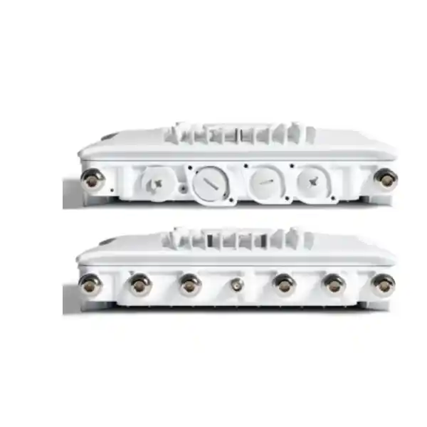
For outdoor UAE installations, cable routing and thermal conditions should be included in power calculations. Long copper runs, high ambient temperature and bundle density can affect resistance and thermal performance. Use cable types, connectors, glands and surge-protection practices compatible with the installation environment. Cisco notes that proper PG 13.5 glands or approved M12 converters are needed on relevant interfaces to maintain the IP67 rating. Environmental protection is an installed-system property, not merely an enclosure specification printed on a datasheet.
A pre-sales power audit should answer six questions: what powers the AP, how much power can the source deliver at the endpoint, what mode is expected, which wired interface is active, what happens during a switch or PSU failure, and how maintenance staff can safely isolate the device. Getting those answers into the design document prevents field surprises.
Rugged construction, IP67 protection and environmental suitability
Cisco builds the IW9167I around a cast-aluminum enclosure for industrial and outdoor locations. The platform is IP67-rated when installed in accordance with the hardware guidance and correct sealing accessories. In practical terms, that means the enclosure is engineered for ingress protection against dust and temporary water immersion conditions defined by the rating, but the deployment must still follow installation requirements. Open ports, incorrect glands, loose fittings, unsuitable cable jackets or poor service-loop practices can compromise environmental protection even when the access point itself is ruggedized.
Cisco lists an operating temperature range for the IW9167I of approximately -50°C to 65°C. That range gives substantial thermal headroom for many UAE industrial and outdoor installations, but ambient air temperature is not the only consideration. A unit mounted in direct solar exposure on a dark wall or metal pole can absorb significant radiant heat. The surrounding structure, airflow, mounting orientation and cable-entry details can all influence real thermal stress. Site engineering should therefore evaluate the microenvironment rather than relying only on a city weather forecast.
The physical dimensions are approximately 11.5 x 10.5 x 3.0 inches, or 29.2 x 26.7 x 7.6 cm, with a weight around 8 lb or 3.6 kg. These figures matter for pole loading, bracket selection, installation labor, lift access and maintenance planning. The access point is substantially more robust than a typical indoor ceiling AP, so installers should prepare mounting points accordingly. A wall must have suitable structural strength and fasteners; a pole mount must use correct brackets and hardware; rooftop or yard placements should account for wind and cable movement.
The product also includes surge protection characteristics on its wired interfaces, but a complete lightning and surge strategy may require external measures according to site design, exposure and local practice. Bonding, grounding, shield termination, surge devices, cable route and separation from high-energy conductors should be considered as a system. Outdoor copper entering a building deserves particular attention because it can create a path for transient energy. Fiber can provide galvanic isolation between network zones, although local power still requires proper surge and grounding design.
For harsh industrial sites, also evaluate chemicals, vibration sources, wash-down practices, nearby process heat, explosive-atmosphere classification and corrosive conditions. The IW9167I is a rugged industrial access point, but it is not the hazardous-location version of the series. Where a site is classified for hazardous gases or dusts, select hardware that carries the required hazardous-location approvals and confirm the certification against the exact zone or class. Do not substitute a standard rugged model where a certified hazardous-location product is mandated.
Cisco Catalyst controller integration, software and licensing
In Wi‑Fi access-point mode, Cisco documents the IW9167I for operation with Cisco Catalyst 9800 Series Wireless Controllers, including physical or virtual controller options. Cisco also specifies IOS XE software requirements for the platform, with IW9167I access-point support beginning from the documented release train. For a production design, compatibility should be checked against the exact controller model, controller software release, access-point image, licensing state and any high-availability architecture before change approval.
Controller-based operation is valuable for industrial WLANs because it centralizes SSID configuration, security policy, RF management, telemetry, client visibility, software lifecycle and troubleshooting. Large operational sites often have hundreds or thousands of devices, and manual AP-by-AP management quickly becomes unsustainable. A Catalyst controller architecture can provide consistent WLAN policy across indoor and industrial access points while still allowing site-specific RF profiles, tags and network segmentation.
Cisco lists Industrial Wireless Cisco DNA Essentials and DNA Advantage licensing options for Wi‑Fi deployments. The appropriate tier depends on the required management and feature set, organizational agreement and lifecycle strategy. Licensing should be quoted as part of the solution rather than treated as an afterthought. Procurement teams should identify license term, support coverage, controller entitlements, renewal ownership and whether the project is part of a broader Cisco enterprise agreement.
The access point also includes 2 GB DDR4 memory and 1 GB NAND flash according to Cisco hardware documentation. These internal resources support the software platform and operational features; they are not user storage for application data. The device includes a management console port, reset control and multicolor system LED for installation and service workflows. Access to these interfaces should be considered during mounting so technicians can service the AP without unnecessary removal or unsafe access procedures.
For enterprise deployments, the wireless controller should not be designed in isolation. Confirm IP addressing, DHCP behavior, DNS, NTP, authentication services, RADIUS reachability, certificate requirements, firewall rules, QoS, multicast behavior and telemetry paths. Where WLAN traffic crosses security zones, FourTeck Firewall Dubai can support policy design so industrial wireless traffic is segmented appropriately from corporate, guest, server and operational technology networks.
Wi‑Fi 6 functions that matter in real industrial networks
Wi‑Fi 6 improves the way a shared radio channel is used. In industrial settings, that is more important than a single-client speed test. A warehouse cell may contain handheld scanners, forklift terminals, tablets, voice clients, cameras, sensors and maintenance laptops at the same time. The objective is to keep airtime contention controlled and application latency predictable while clients move between cells. Features such as OFDMA and MU-MIMO help the infrastructure schedule transmissions more efficiently when clients support them.
OFDMA divides a channel into smaller resource units so multiple clients can be served within the same scheduling interval. For applications that send small, frequent packets, this can reduce the inefficiency associated with every client contending for an entire channel. MU-MIMO allows simultaneous spatial communication with multiple compatible clients under suitable RF conditions. BSS coloring adds a mechanism to identify overlapping basic service sets and can improve spatial reuse in dense deployments. Target Wake Time can improve power efficiency for compatible clients by coordinating wake schedules, which can matter for battery-powered devices.
These protocol improvements work best when clients are modern and properly configured. A WLAN serving a mixed fleet must still accommodate older devices. Some industrial scanners remain in service for many years and may support older 802.11 generations, limited channel widths, basic roaming behavior or only 2.4/5 GHz. A design should inventory the client radio chipset, driver version, supported channels, security methods, minimum data rates and roaming behavior. The access point can be technically advanced while the application experience is constrained by the least capable endpoint.
WPA3 support is another important capability. Security policy should be selected according to client compatibility and the organization’s authentication architecture. Enterprise networks often use 802.1X with RADIUS-backed identity, certificate-based EAP methods, role or VLAN assignment and centralized policy. Industrial IoT devices that cannot support enterprise authentication may require dedicated SSIDs or alternate segmentation. Avoid building one large shared pre-shared-key WLAN for every device type merely for convenience; operational simplicity at deployment time can create security and lifecycle complexity later.
The correct approach is to map wireless features to business outcomes: reduced contention for scanners, predictable roaming for mobile terminals, stronger identity controls for workforce devices, isolated access for contractors, and capacity headroom for future Wi‑Fi 6E clients. Feature lists become valuable only when they are translated into a documented WLAN policy.
UAE deployment scenarios for the Cisco IW9167I
Warehousing and distribution
Use rugged wireless cells for scanners, tablets, voice devices, printers, vehicle-mounted terminals and maintenance laptops across loading docks, external staging areas and semi-open warehouses. RF design should consider rack geometry, inventory density and moving vehicles.
Manufacturing
Connect operator terminals, engineering laptops, industrial mobile devices and approved OT endpoints where dust, heat and process conditions require more rugged hardware than office access points. Segment production traffic from corporate WLANs.
Ports and logistics yards
Provide broad outdoor coverage for handhelds, vehicle terminals and workforce devices. Plan mounting around containers, cranes, trailers and constantly changing obstructions, and use fiber where electrical isolation or long distance makes it preferable.
Utilities and infrastructure
Deploy at substations, treatment facilities, campuses and field compounds where rugged wireless is needed for authorized staff and operational applications. Confirm electrical, grounding, security and site-access requirements before installation.
Transport facilities
Support yards, depots, maintenance zones and passenger-service back-of-house areas with enterprise WLAN coverage. Validate fast-moving client behavior and application roaming requirements with actual device tests.
Large campuses
Extend controller-managed wireless beyond office ceilings to courtyards, perimeter areas, service roads, plant spaces and building exteriors while preserving centralized security and operational visibility.
RF sizing methodology: coverage, capacity and roaming
A reliable IW9167I deployment begins with a predictive design and, where business impact warrants it, a physical site survey. The first step is to build an accurate floor plan or site map with dimensions, wall materials, rack locations, machinery, open yards, mounting candidates and network closets. The second step is to classify client types and applications. A scanner performing barcode transactions has different throughput and roaming needs from a video endpoint or maintenance laptop. The third step is to define service-level targets such as minimum received signal strength, signal-to-noise ratio, tolerated packet loss, application latency and roaming continuity.
Coverage is not the same as usable service. A client may display a Wi‑Fi icon while operating at a low modulation rate that consumes excessive airtime. A good design aims for enough signal and SNR to sustain the required data rate throughout the operational area, including cell edges. Capacity is then layered onto the coverage design by calculating active clients per cell, expected airtime consumption and traffic patterns. High-density locations such as loading docks or shift-change areas may require more APs even if a single AP can physically cover the space.
Roaming design requires controlled overlap. Too little overlap creates dead zones; too much overlap causes sticky clients and co-channel interference. The optimal cell size depends on client behavior and band. Industrial handhelds sometimes roam differently from laptops or phones, and vehicle-mounted devices can cross coverage boundaries quickly. Validate actual production hardware, not just a generic survey adapter. Driver settings, roaming aggressiveness, power-save mode and antenna placement can materially affect behavior.
Mounting position should be chosen from the client perspective. In a tall warehouse, putting APs at roof height can create an easy installation but a poor RF outcome because racks and stock attenuate signals vertically and laterally. Side-wall or under-rack placements may improve service depending on the environment. In an outdoor yard, mounting on perimeter poles can simplify infrastructure but may leave vehicle shadow zones behind dense rows of containers or equipment. Sometimes a grid of lower-height poles delivers more predictable coverage than a few high-power perimeter nodes.
Channel width is another sizing parameter. Wider channels improve potential peak throughput but reduce the number of independent channels available for reuse. In dense deployments, 20 or 40 MHz channels may create a healthier airtime environment. Transmit power should be balanced with client capability; excessive AP transmit power can create one-way coverage where clients hear the AP but cannot respond reliably. Automatic RF management can optimize within defined boundaries, but the engineer should establish sensible channel and power policies first.
After installation, conduct validation measurements using the production configuration. Confirm coverage, SNR, noise floor, channel utilization, retry rates, roaming events, client data rates and application performance. Compare observed results with the design targets and make controlled adjustments. A post-deployment survey turns the WLAN from an assumption into an engineered service.
Deployment topology choices
The IW9167I can be used in multiple physical network designs. The most common enterprise topology is a controller-managed access point connected by copper to a nearby switch that provides both Ethernet and sufficient PoE. This is straightforward when network cabinets are within copper distance and the switching platform supports the required power class and multigigabit rate. The design should reserve enough switch capacity for all APs and future growth.
A second topology uses fiber for the production uplink and local DC power for the AP. This can be attractive in large yards, electrically noisy industrial environments or between network zones where copper length is impractical. Fiber removes the copper-distance constraint and improves electrical isolation, but it requires compatible optics, clean fiber management, local power engineering and protected splice or termination points. The SFP selection must match the fiber type, distance and switch optics.
A third topology uses industrial access switching positioned closer to the operational area. The switch can aggregate several IW9167I units and other edge devices, then uplink over resilient fiber to the core. This approach can reduce long home-run cabling, but it shifts environmental and power requirements to the switch cabinet. Ensure the access switch has the appropriate industrial rating, temperature capability, redundant input design and PoE budget.
High-availability designs should examine the entire path. A WLAN with redundant wireless controllers can still fail if every AP depends on one access switch, one power supply or one fiber. Conversely, duplicating every component may be unnecessary for noncritical coverage areas. Classify zones by business impact and apply redundancy where the operational requirement justifies it. Production lines, automated yards or safety-related communication zones may warrant stronger resiliency than visitor parking.
Where the wireless system supports applications hosted in local data centers or edge servers, check latency, routing and firewall policy end to end. FourTeck can align the WLAN with compute and data-center connectivity through Server Dubai, particularly for UAE customers consolidating wireless, switching, security and infrastructure requirements into one deployment plan.
Security architecture for industrial WLANs
Industrial wireless should be treated as a security boundary, not simply a radio extension of the office LAN. The IW9167I supports modern enterprise WLAN security features through the Cisco Catalyst architecture, including WPA3 capabilities. The production policy should define which identities are allowed onto each SSID, how they authenticate, what network segment they receive, what applications they may reach and what happens when a device no longer meets policy.
For employee and managed-device WLANs, 802.1X authentication with a RADIUS service is generally preferable to a shared password because credentials can be tied to user or device identity and revoked individually. Certificate-based methods can strengthen device authentication and reduce reliance on user-entered passwords. Industrial devices may not support every enterprise EAP method, so compatibility testing is necessary. Where older or embedded clients need pre-shared credentials, isolate them in dedicated segments and restrict their permitted destinations.
Segmentation should map to operational risk. Corporate users, contractors, guest devices, scanners, OT maintenance clients, cameras and IoT endpoints should not automatically share one broadcast domain. Separate VLANs or policy segments can limit lateral movement and allow firewalls or access-control systems to enforce least-privilege communication. A scanner might need only the warehouse-management application, DNS, DHCP and time services. A camera might need only a recorder. A maintenance laptop may need broader access but only during authorized windows.
Wireless intrusion monitoring and RF visibility are also important in operational spaces. Unauthorized access points, personal hotspots and non-Wi‑Fi interference can affect performance and security. Controller telemetry should be integrated into operational monitoring so teams can distinguish an RF problem from an authentication, DHCP, routing or application issue. Logging must have synchronized time and enough retention to investigate incidents after the fact.
Security design should also cover the management plane. Use secure administrative access, role-based privileges, centralized identity, backup procedures, controlled software upgrades and configuration-change records. Industrial networks often have longer change windows than office IT, so a defined lifecycle is essential. The access point is one component of a larger trust architecture that includes controller, switch, firewall, RADIUS, DNS, DHCP, monitoring and endpoint configuration.
Installation engineering and field workmanship
Rugged wireless performance depends heavily on installation quality. Start with the mounting drawing and verify that the bracket, pole diameter, wall substrate and fasteners are appropriate. Maintain access to the service interfaces and make sure cable entries are not placed where water can pool. Use drip loops where appropriate, support cable weight and avoid tight bend radii. If the device is installed above production equipment or traffic, follow site safety procedures for working at height and secure all hardware against vibration.
Cable selection should match both bandwidth and environment. A multigigabit copper uplink may require high-quality balanced cabling with correct category performance, shield handling and termination. Outdoor cable needs suitable jacket ratings and pathway protection. Industrial areas may require separation from high-voltage conductors, variable-frequency drives or motors. If M12 interface conversion is used, verify the exact Cisco-supported converter and make sure installation preserves the intended ingress protection.
Cisco notes that PG 13.5 glands or appropriate M12 converters are required with Ethernet and power interfaces to maintain IP67. This requirement should be included in the bill of materials and method statement. A common field error is to order the main access point and postpone the small accessories until installation. That causes delays or encourages improvised sealing, which is unacceptable for a rugged outdoor project.
Grounding and bonding should be designed with the site electrical engineer. Do not assume the shield of a network cable is a substitute for a proper bonding conductor. For outdoor placements, assess lightning exposure and surge paths. Where copper transitions from outdoors to indoors, use appropriate protection and bonding practices according to the project standard. Fiber is often attractive for long exposed uplinks because it is nonconductive, but power conductors and mounting metalwork still need appropriate protection.
Commissioning should be systematic. Record serial numbers, regulatory domain, software version, switch port, cable ID, IP information, mounting coordinates and photos. Verify PoE negotiation or DC input, wired link speed, controller join, SSID availability, authentication, DHCP, DNS, application reachability and RF metrics. A documented commissioning pack makes future troubleshooting much faster than relying on technician memory.
Finally, plan maintenance access. Outdoor APs may need inspection after severe weather or construction changes. Industrial facilities may accumulate dust or introduce new metal structures that affect propagation. Keep an up-to-date as-built drawing and schedule periodic wireless health reviews so the network evolves with the site.
Performance expectations and realistic throughput planning
The IW9167I is capable of very high PHY rates when client capability, modulation, channel width and spatial streams align, but enterprise planning should separate radio link rate from usable application throughput. Wi‑Fi is a shared, half-duplex medium. Management frames, acknowledgments, contention, retransmissions, encryption overhead and neighboring clients all consume airtime. A four-spatial-stream AP does not make a two-stream handheld become a four-stream device. Most mobile endpoints use fewer spatial streams than the infrastructure.
Capacity calculations should therefore begin with expected application traffic. Barcode scanning may use little bandwidth but be sensitive to latency and roaming interruption. Voice requires modest bandwidth but consistent jitter and packet delivery. Video can consume substantial sustained throughput. Software updates or file transfers can create bursts. Instead of promising a fixed Mbps number per client, model the busy hour and confirm that channel utilization remains within an acceptable operating range.
Signal quality also affects airtime. A client at the edge of coverage transmits more slowly and may require retries, consuming a disproportionate share of the channel. This is why a WLAN with strong coverage often supports more clients than one that merely reaches the same area. Minimum data-rate policies can prevent very slow legacy rates from consuming excessive airtime, but those settings must be tested against older industrial clients.
When multigigabit uplinks are used, ensure the upstream path can actually carry the traffic. The access switch uplinks, distribution layer, firewall, WAN, application servers and internet circuit may become the next bottleneck. For a large site, performance monitoring should correlate wireless channel utilization with wired interface utilization and application latency. This makes it possible to determine whether a user complaint originates on the RF link or elsewhere.
For high-capacity projects, use a pilot zone before broad rollout. Test the target client population, actual applications, roaming routes and busy-hour behavior. Pilot results can refine access-point spacing, channel width, transmit power and QoS policy before the project scales across dozens of locations.
6 GHz readiness and UAE regulatory planning
Cisco includes 6 GHz hardware support in the IW9167I, enabling Wi‑Fi 6E capability where the applicable country regulations, regulatory domain, software and deployment rules permit operation. Procurement teams should not assume that a product described globally as Wi‑Fi 6E can use every 6 GHz channel at every power level in every country. Cisco explicitly makes 6 GHz usage subject to the approvals of the local regulatory agency.
For a UAE order, confirm the current Cisco regulatory-domain mapping and local permitted operating conditions at the time of quotation. Regulatory approvals and channel rules can evolve. The exact orderable part number contains a regulatory-domain designator, and the correct selection should be verified before purchase. This protects the customer from receiving hardware whose permitted channel set does not match the deployment country.
Client readiness is equally important. Existing industrial devices may have no 6 GHz radio, while newer laptops, tablets and phones may support Wi‑Fi 6E. A phased design can keep legacy devices on 2.4/5 GHz and introduce 6 GHz for compatible clients. Because 6 GHz does not have the same legacy-client population as older bands, it can provide a cleaner capacity layer, but coverage should be validated because propagation through walls, racks and machinery may differ from 5 GHz.
Security requirements for 6 GHz should also be incorporated into client testing. Modern security modes are integral to the Wi‑Fi 6E ecosystem, and some legacy security configurations are not appropriate for 6 GHz operation. Validate authentication, certificates, supplicant behavior and roaming before migrating production applications.
The recommended procurement language is therefore precise: the IW9167I is 6 GHz hardware capable and supports Wi‑Fi 6E under approved regulatory conditions. FourTeck will confirm the appropriate UAE part number, controller compatibility and proposed operating bands for the project rather than making a blanket assumption about spectrum availability.
BLE and GNSS capabilities
Beyond the primary Wi‑Fi radios, the IW9167I includes Bluetooth Low Energy and integrated GNSS hardware. BLE can support location, proximity or IoT-related workflows in compatible Cisco architectures and applications. The built-in BLE antenna keeps the radio function within the sealed integrated enclosure. For organizations considering asset tags, location services or operational telemetry, the presence of BLE can reduce the need for a separate radio platform at each coverage point.
GNSS capability can support positioning and time-related platform functions where the antenna has an adequate view of the sky and the software use case supports it. Site placement matters because metal roofs, indoor mounting and dense structures can reduce satellite visibility. The integrated GNSS antenna is therefore a capability to be designed around, not a guarantee that every mounting location will produce the same reception quality.
For projects that plan to use BLE or GNSS operationally, include those requirements during the RF and physical survey. A location chosen only for Wi‑Fi coverage may not be optimal for GNSS reception. Similarly, BLE design may require different density or placement considerations depending on the application and tags. When these functions are not part of the initial project, their presence can still preserve options for future services.
Treat IoT integration as an architecture project rather than a feature checkbox. Define which platform consumes the telemetry, how devices are identified, where data is stored, what network access is required and how privacy and security policies are enforced. This avoids installing a capable radio layer without a complete operational workflow.
How to compare the IW9167I with other industrial access-point choices
Select the IW9167I primarily when an integrated omnidirectional antenna system matches the RF design. Compared with an external-antenna industrial AP, it simplifies the bill of materials and reduces the number of exposed RF connectors and coaxial components. That can reduce installation variability and make field replacement easier. The tradeoff is less freedom to choose directional, sector or specialty antennas.
Compare environmental ratings carefully. A rugged outdoor AP and a hazardous-location AP solve different problems. IP67 indicates ingress protection; it does not automatically certify the device for explosive atmospheres. If the facility has classified zones, use the variant that carries the necessary hazardous-location certifications and verify that the certification matches the project specification.
Compare radio architecture based on client requirements. The IW9167I’s 4×4:4 radios provide strong infrastructure capability, but the benefits depend on channel plan, client spatial streams and actual airtime. A smaller 2×2 AP may be sufficient for low-density telemetry, while 4×4 hardware provides greater flexibility for demanding enterprise access. The question is not which number is larger; it is which architecture meets the service target with appropriate cell density.
Compare wired interfaces and power. If the intended switch can provide only 1 Gbps and limited PoE, the system may not realize the access point’s full capability. If the site requires fiber directly to the AP, the integrated SFP option is valuable. If a local DC system is already available, the dual power choices can simplify the physical architecture.
Finally, compare management ecosystem and lifecycle. Organizations standardized on Cisco Catalyst 9800 controllers, Cisco enterprise identity and Cisco network operations may gain operational consistency from the IW9167I. A technically capable access point is more valuable when it fits the organization’s monitoring, software upgrade, support and troubleshooting processes.
The best comparison therefore weighs six dimensions together: RF pattern, environmental certification, client density, uplink and power, controller ecosystem and lifecycle support. Purchase price alone is a weak decision metric for infrastructure expected to operate for years in difficult locations.
Lifecycle operations, monitoring and maintenance
Industrial WLANs should be operated with measurable health indicators. Monitor client counts, channel utilization, retry rates, noise, SNR, authentication failures, DHCP latency, roaming events, switch interface errors, PoE state and uplink utilization. Establish a baseline during commissioning so later deviations are easier to identify. A raw alarm without a baseline may show that something changed but not whether the change matters to production.
Software lifecycle is equally important. Cisco periodically publishes software updates, security advisories, field notices and compatibility guidance. Before upgrading a production controller, confirm the release supports the access-point hardware and key client functions. Use a staged rollout, starting with a test controller or limited site group where possible. Industrial clients can expose driver or roaming behaviors that were never visible in office testing.
Maintain configuration backups and a rollback plan. Document which access points serve critical areas and schedule changes around production windows. If the network uses certificates, monitor expiration dates. If licensing has a term, track renewal ownership early enough to avoid operational surprises. If RADIUS, DHCP or DNS services are redundant, test that failover actually works from the wireless client perspective.
Physical maintenance should inspect cable glands, brackets, visible corrosion, damaged jackets, loose service loops and signs of water ingress. In dusty environments, external surfaces may accumulate material that changes thermal behavior. In yards, construction or new racking can alter RF propagation. Update the site survey when major physical changes occur rather than assuming the original design remains valid forever.
Spare strategy depends on business impact. A small noncritical campus may rely on supplier lead time, while a production plant may hold one or more configured spares. Keep mounting and interface accessories with the spare so a failed unit can be replaced without waiting for small parts. Record replacement serial numbers and synchronize asset-management data after every change.
Procurement and bill-of-materials planning for UAE projects
A complete IW9167I quotation should include more than the base access point. Start with the correct orderable AP part number and regulatory domain. Add the required Cisco wireless licensing and support coverage. Identify mounting brackets and any approved M12 converters or cable glands needed by the chosen interface method. If copper is used, specify cable category, surge protection and switch-side transceivers or ports. If fiber is used, specify SFP optics, fiber type, patch cords, termination hardware and local DC power.
Switching must be quoted with enough PoE class and total budget. Check whether the access switch supports 2.5/5 Gbps multigigabit Ethernet, whether it can deliver the intended PoE class on all simultaneously active ports, and whether its uplink capacity is adequate. For industrial switches, confirm temperature, redundancy and mounting compatibility. If standard enterprise switches are used in air-conditioned cabinets, ensure the field cable run stays within design limits.
Controller capacity should include current AP count plus growth. Confirm whether the customer already operates a Catalyst 9800 controller, whether the model supports the planned scale, how high availability is configured and how licenses are assigned. Greenfield customers may need a physical or virtual controller architecture, management platform integration and identity services. These infrastructure components can be more important to project success than the individual AP model.
For UAE procurement, also capture delivery location, access restrictions, installation hours, permit requirements, lift or scaffold needs and any site induction procedures. An access point mounted on a twelve-meter yard pole has a very different labor and safety profile from one mounted on a warehouse wall. Separating hardware cost from installation method prevents surprises during project execution.
Spare units, spare optics, spare glands and replacement brackets may be worthwhile for mission-critical sites. If the customer has multiple facilities, standardize the BOM where practical so field teams carry fewer unique components. At the same time, do not force one universal design onto locations with different RF conditions. Standardize the platform and process while allowing the survey to determine AP quantity and placement.
The final commercial proposal should state assumptions clearly: number of APs, controller status, licensing tier, regulatory-domain verification, 6 GHz conditions, power source, uplink media, mounting hardware, survey scope, installation scope, configuration scope, acceptance testing and support period. Clear assumptions protect both the customer and the implementation team.
Technical specification summary
| Area | IW9167I capability | Design implication |
|---|---|---|
| Wireless | Wi‑Fi 6 / 6E hardware support; 2.4, 5 and 6 GHz radios | Confirm UAE regulatory domain, client support and channel plan. |
| MIMO | 4×4:4 integrated radio/antenna architecture | Useful for capacity, but client spatial-stream capability still governs each link. |
| Copper uplink | 100M / 1G / 2.5G / 5G multigigabit Ethernet | Pair with multigigabit access switching to avoid unnecessary wired bottlenecks. |
| SFP | Fiber or copper options, up to 10 Gbps depending on interface/media | Useful for long-distance or electrically isolated industrial uplinks. |
| Power | PoE+, higher-power PoE/UPOE-class input, or 24–48 VDC nominal | Power class can affect radio and interface operation; size switch budget carefully. |
| Environmental | IP67, rugged cast-aluminum enclosure | Correct glands, adapters and field workmanship are required to maintain protection. |
| Temperature | Approximately -50°C to 65°C operating range | Evaluate direct solar load and local microenvironment, not just ambient weather. |
| Integrated services | BLE and GNSS | Can support compatible IoT, location and operational workflows. |
| Management | Cisco Catalyst 9800 controller support in AP mode | Integrate licensing, controller compatibility, identity and lifecycle management. |
Frequently asked engineering questions
Is the IW9167I suitable outdoors?
Yes. It is built for industrial and outdoor environments and carries an IP67 rating when installed correctly with the required interface sealing components. Mounting, cable glands, surge protection and grounding remain part of the complete outdoor design.
Does it support Wi‑Fi 6E?
The hardware includes 6 GHz support and can operate as Wi‑Fi 6E where the applicable country regulation, software and configuration permit. Confirm the UAE regulatory domain and allowed 6 GHz operation before ordering.
Does it have internal antennas?
Yes. The IW9167I uses integrated omnidirectional antennas for 2.4, 5 and 6 GHz, plus integrated BLE and GNSS antennas. This simplifies installations that do not require a custom directional RF pattern.
Can it use fiber?
Yes. The SFP interface can support fiber up to 10 Gbps with the appropriate design and transceiver. A fiber deployment normally uses local DC power because fiber does not deliver PoE.
Can standard PoE+ power it?
Cisco supports 802.3at PoE+, but the AP operates in a reduced-power profile compared with higher-power input. If full 4×4 radio behavior and high-speed interfaces are required, design for the appropriate higher-power source.
Which controller is used?
Cisco documents support for Catalyst 9800 Series Wireless Controllers in Wi‑Fi access-point mode. Validate the exact controller platform and software release against the final AP configuration before deployment.
Decision recap: when the IW9167I is the right fit
The Cisco Catalyst IW9167I is a strong fit when the project needs Cisco enterprise wireless in a ruggedized integrated-antenna format. It is particularly compelling for broad omnidirectional coverage where the physical environment requires IP67 protection and where the network design can benefit from Wi‑Fi 6E readiness, 4×4 radios, a multigigabit copper interface, SFP flexibility, BLE and GNSS. It is less appropriate when the RF plan requires highly directional external antennas or when the site requires hazardous-location certifications that belong to a different product variant.
Strong reasons to select
Rugged outdoor/industrial build, integrated antennas, 4×4:4 radios, Wi‑Fi 6E capability, multigigabit Ethernet, SFP up to 10 Gbps, BLE, GNSS, PoE or DC power, and integration with Cisco Catalyst wireless operations.
Items to verify before PO
UAE regulatory domain, 6 GHz permissions, controller software compatibility, Cisco licensing, PoE class, switch budget, uplink medium, SFP type, mounting kit, cable glands or M12 adapters, grounding, surge strategy and survey-derived quantity.
Quotation input checklist
For an accurate FourTeck UAE quotation, provide as much of the following information as available. Missing details can be developed during a survey or design workshop, but capturing them early improves BOM accuracy and avoids over- or under-specification.
Plan the IW9167I as a complete industrial wireless system
A successful industrial WLAN is the result of matched radio design, switching, power, controller software, security policy, cabling, environmental protection and lifecycle operations. FourTeck can help UAE organizations turn the Cisco Catalyst IW9167I specification into a deployable architecture with a clear bill of materials and acceptance plan.
For best results, begin with a site map and client inventory, then validate regulatory-domain requirements, controller compatibility, power class and uplink method. From there, define AP placement, channel widths, security segments, installation materials and post-deployment validation. This process reduces rework and helps ensure the selected access points deliver the intended operational outcome rather than simply appearing on a hardware list.

Reviews
There are no reviews yet.