
Cloud-managed multigigabit access switching for modern UAE networks
Cisco Meraki MS130-24X in Dubai, UAE
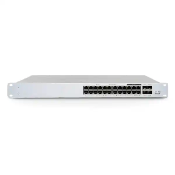
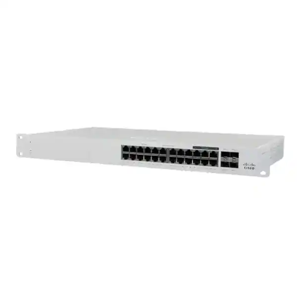
The Cisco Meraki MS130-24X combines 18 Gigabit Ethernet access ports, six 2.5GbE multigigabit ports, four 10GbE SFP+ uplinks, a 370W PoE budget and centralized Meraki Dashboard management in a 1U access-switch platform. It is particularly relevant when a branch, office, education site or distributed campus needs more bandwidth for Wi-Fi access points and selected high-speed endpoints without moving every copper port to multigigabit speeds.
Direct answer: what is the Cisco Meraki MS130-24X?
The MS130-24X is a Cisco Meraki cloud-managed Layer 2 access switch in the MS130 family. It is the 24-port-density X model, distinguished by six multigigabit copper ports, four 10GbE SFP+ uplinks, PoE capability and Meraki Dashboard operation.
It is mainly used as an access-layer switch for users, Wi-Fi access points, IP phones, cameras, IoT devices and other Ethernet endpoints where several ports benefit from 2.5GbE and the switch needs faster fibre or DAC uplinks to distribution infrastructure.
UAE organizations standardizing on Meraki cloud management, especially branches and medium-density campus areas with newer wireless access points, should consider it when 24-class port density and selective multigigabit access are appropriate.
Confirm the Meraki licensing model and tier, the required license term, total PoE demand, which endpoints truly need 2.5GbE, the type and reach of each uplink, and whether 24-class access density leaves enough spare capacity for growth.
FourTeck can help map ports to endpoints, calculate PoE demand, identify suitable SFP/SFP+ optics or twinax cables, review existing Meraki organization licensing, plan rack and power requirements, and compare the MS130-24X with smaller, non-mGig or 48-port alternatives.
Where the MS130-24X fits in a business network
The strongest reason to shortlist the Cisco Meraki MS130-24X is not simply that it is a managed 24-port switch. Its value comes from the specific mix of port speeds and cloud operations. Many modern access networks are in transition: most desktop devices, printers, phones and general-purpose endpoints still operate comfortably at 1GbE, while selected Wi-Fi access points, high-performance workstations, edge appliances or local devices can benefit from more than 1GbE. Building every copper access port as 2.5GbE can increase cost without creating a matching business benefit. The MS130-24X takes a selective approach by giving the buyer eighteen conventional 1GbE copper ports and six 2.5GbE-capable mGig copper ports.
That port mix can make the switch well matched to an office floor or branch where a modest number of modern wireless access points need multigigabit connections but the remainder of the connected estate remains Gigabit Ethernet. It also gives the network designer a way to separate bandwidth-sensitive endpoints from ordinary access ports without adding a second switch solely to obtain higher-speed copper. The four 10GbE SFP+ interfaces then provide headroom for uplinks to aggregation or distribution switching, server-side connectivity in suitable designs, or resilient uplink arrangements where the broader topology supports them.
The model is a Layer 2 access switch rather than a general replacement for every distribution or core requirement. That distinction matters during procurement. A buyer whose main problem is user and device access can focus on port density, PoE, VLAN segmentation, authentication, monitoring and uplink design. A buyer who actually needs a different forwarding architecture, substantially larger port counts, different redundancy characteristics or higher aggregation capacity should compare a different Meraki family or a larger platform rather than choosing the MS130-24X simply because its uplinks are fast.
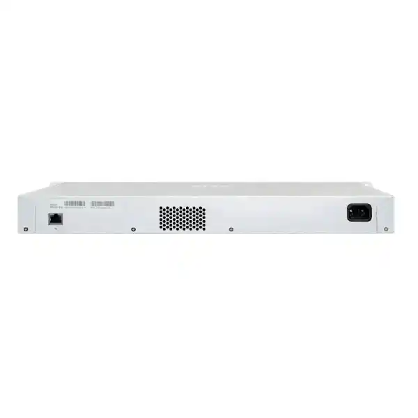
For Dubai and wider UAE deployments, practical site considerations also deserve attention. The MS130-24X uses an integrated 1U rack-mount form factor, an internal fixed power supply and active fan operation. It should therefore be installed in an appropriate communications rack or controlled equipment area with suitable ventilation, power protection and cable management. Its published operating temperature range is 0°C to 45°C. That specification is especially relevant in the UAE because a communications room, warehouse cabinet or remote site can exceed acceptable equipment temperatures if cooling is inadequate. The correct design is to treat the switch as network infrastructure requiring an engineered environment rather than assume that any enclosed cabinet will be suitable.
Verified Cisco Meraki MS130-24X specifications
The table below concentrates on model-specific data that materially affects sizing, installation and quotation. It is intended to help a buyer distinguish the MS130-24X from the ordinary MS130-24 and MS130-24P variants rather than rely on family-level descriptions.
| Specification | MS130-24X detail | Buyer relevance |
|---|---|---|
| Standard copper ports | 18 × 1GbE RJ45 | Suitable for standard user devices, phones, printers, cameras and other Gigabit endpoints. |
| Multigigabit copper ports | 6 × 100M/1G/2.5GbE mGig RJ45 | Provides selective higher-speed access for compatible Wi-Fi APs or other endpoints without making every copper port multigigabit. |
| Uplink interfaces | 4 × 10GbE SFP+ | Enables higher-speed fibre or compatible direct-attach uplinks. Optic type and link distance must be matched to the network design. |
| Dedicated management | 1 dedicated management interface | Useful for implementation and management design where a dedicated interface is required. |
| PoE type and per-port level | 802.3bt, up to 30W per port | Endpoint draw still needs to be checked individually; the label alone does not prove every device can be powered in every combination. |
| Total PoE switch budget | 370W | Calculate the actual combined draw of phones, APs, cameras and other powered devices with sensible growth margin. |
| Switching capacity | 146Gbps | Helps position the model for its access-layer role and differentiate it from non-X MS130 variants. |
| Power input | 100–240V AC, 8A–4A, 50–60Hz | Confirm suitable rack PDU, regional power cord and UPS design for the installation. |
| Power load | 50W idle / 421W maximum | Useful for UPS sizing, cabinet thermal planning and electrical load calculations. |
| Operating temperature | 0°C to 45°C | Communications rooms and cabinets in UAE sites require dependable cooling and airflow. |
| Storage / transport temperature | -20°C to 70°C | Relevant for logistics and storage, but not a substitute for the narrower operating range once powered. |
| Humidity | 5% to 95% | Installation should still use a clean, suitable network equipment environment and follow Cisco conditions. |
| Mounting | Integrated 1U rack mount | Plan one rack unit plus practical space for cable management and ventilation. |
| Power supply | Fixed internal | The power architecture should be considered when comparing resilience expectations with other switch families. |
| Fan operation | Fixed internal fan | Best placed in a proper communications room or cabinet rather than beside users in a quiet work area. |
| Dimensions | 1.73 × 17.32 × 10in / 4.4 × 44 × 25cm | Check usable rack depth, especially in wall-mounted cabinets with patch panels and rear power connections. |
| Weight | 9.37lb / 4.25kg | Relevant for rack handling and cabinet planning, particularly in smaller wall racks. |
Why the six 2.5GbE ports matter
Wi-Fi access point uplinks
Modern wireless deployments can create more than 1Gbps of aggregate traffic under suitable conditions. A 2.5GbE wired connection can therefore be useful for selected access points because it reduces the chance that a single 1GbE Ethernet link becomes the first obvious bottleneck. The MS130-24X gives six such ports, so a buyer can reserve them for higher-throughput AP locations and continue using the remaining eighteen 1GbE ports for ordinary access devices. The important sizing question is the number of APs that genuinely require mGig at each closet, not the total number of wireless access points across the organization.
A practical migration stage
Many organizations replace access switching before every endpoint is ready for multigigabit speeds. The mixed-speed design allows a staged migration. Existing Gigabit devices continue to use the standard ports while newly deployed devices can be placed on the mGig interfaces. This can make budgeting more controlled, but it also means the port map should be planned in advance. If the site already expects more than six devices that require 2.5GbE, the MS130-24X may be undersized for that specific closet even if the total copper-port count looks adequate.
Cabling remains part of the result
A switch port marked 2.5GbE does not guarantee that every installed horizontal cable run will deliver the intended result. Cable category, termination quality, run length, patch leads, patch panels, interference and the endpoint’s own Ethernet capability all matter. When an MS130-24X is being introduced specifically to improve AP uplink bandwidth, the correct project scope should include verification of the existing structured cabling rather than treating the switch replacement as an isolated hardware task.
Do not overvalue unused mGig
The X variant deserves its premium when its extra interfaces solve a real access-layer requirement. If a branch has no realistic need for multigigabit copper and 10GbE uplinks, an MS130-24 or MS130-24P may be more economical depending on PoE needs and the intended uplink design. Conversely, if a site needs more than six mGig edge ports or a larger PoE pool, the 48-port X model or another switch family may deserve comparison. Accurate purchasing starts with port mapping rather than model naming.
PoE planning: 370W is a budget, not a device-count guarantee
The MS130-24X provides a published 370W PoE switch budget and supports up to 30W per port. Those figures are useful, but a professional design should not convert 370W into a simplistic device count. Access points, desk phones, cameras, sensors and other powered devices can have very different maximum draw. Some endpoints operate far below their nameplate maximum most of the time but still need enough available power for boot, radio operation, accessory modules or peak conditions. The safe approach is to list each powered endpoint model, record its required PoE standard and maximum expected draw, then total the closet requirement with allowance for sensible expansion.
Port speed and PoE requirements should be planned together. For example, a high-performance wireless access point may be one of the best candidates for a 2.5GbE port and may also be one of the larger PoE consumers in the closet. If six such APs are assigned to the six mGig ports, calculate their combined power demand first, then add phones, cameras and other powered devices expected on the remaining ports. This prevents a design in which the copper-port count is correct but the power pool is tight.
Growth should be treated realistically. Reserving twenty or thirty percent unused power simply as a universal rule can be too conservative in one project and too aggressive in another. Instead, identify likely additions during the expected service life: new access points, additional cameras, new phones, door controllers or other edge devices. If the organization expects a substantial expansion in powered endpoints, it may be better to select a larger switch or distribute loads across multiple access switches rather than consume nearly the entire PoE budget on day one.
Power planning also extends upstream. The switch itself has a published maximum load of 421W and uses an internal power supply. UPS capacity, runtime targets, PDU outlet availability and circuit loading should therefore be considered along with endpoint PoE. A UPS chosen only around the switch’s idle consumption can give misleading runtime expectations once many PoE devices are powered. For critical sites, the battery-backed load should include the networking chain needed for service continuity: switch, upstream router or firewall, ISP termination, and any local systems that must remain available during an outage.
10GbE SFP+ uplink design and optic selection
The four SFP+ interfaces are one of the defining differences between the MS130-24X and the standard 24-port MS130 variants. They can provide up to 10GbE per compatible uplink interface and allow the access switch to connect to suitable aggregation, distribution or other infrastructure without restricting every uplink to Gigabit Ethernet. The presence of SFP+ slots, however, does not determine the physical media by itself. The buyer still has to choose the right optic or direct-attach cable for the topology.
Short-range fibre
Cisco Meraki lists MA-SFP-10GB-SR among supported SFP+ modules for the MS130-24X. Short-range optics are commonly evaluated for suitable multimode fibre links within buildings or data rooms, but the installed fibre type, connector path and required distance must be confirmed before ordering.
Longer optical links
MA-SFP-10GB-LR and MA-SFP-10GB-ER are also listed for SFP+ models in the family. Selection should follow the real fibre plant and reach requirement. Buying a longer-reach optic simply because it sounds more capable can be wasteful and may introduce optical-budget considerations that are unnecessary for short campus links.
Direct-attach options
Cisco Meraki lists MA-CBL-TA-1M and MA-CBL-TA-3M for the SFP+ models. These can be relevant when equipment is close enough for a compatible twinax direct-attach connection, such as within or between nearby rack positions. Port compatibility on both connected devices still needs confirmation.
The MS130-24X also supports listed 1GbE SFP modules on its SFP+ ports, including MA-SFP-1GB-SX, MA-SFP-1GB-LX10 and MA-SFP-1GB-TX. This can be useful in migration scenarios where the switch is capable of 10GbE but an existing uplink remains 1GbE for a period. The presence of that compatibility should not remove the need to understand why the X model is being selected; if all uplinks will remain 1GbE and no mGig access ports are needed, the design should be compared against lower-cost alternatives.
For a quotation, provide the number of uplinks, desired speed, fibre type, approximate link length, connector or patching details where known, and the model of the device at the far end. If redundant links or link aggregation are planned, include that topology as well. These inputs let the quotation reflect the actual cable and transceiver requirement rather than list a switch alone and leave the most important connectivity accessories unresolved.
Meraki Dashboard management and the licensing decision
The MS130-24X is designed to be managed through Cisco Meraki Dashboard. That operating model is central to the product, not an optional convenience to consider after the hardware arrives. Initial deployment normally involves claiming the device into a Meraki organization, adding it to the intended Dashboard network, connecting it so that it can reach the Meraki cloud, allowing firmware activity to complete, and then applying VLAN and port configuration through Dashboard. Organizations purchasing Meraki switching for the first time should therefore plan both the hardware and the management lifecycle.
Cisco documents Enterprise and Advanced license tiers for the MS130 family. For the 24-port class that includes MS130-24, MS130-24P and MS130-24X, the Enterprise license family is LIC-MS130-24-xY and the Advanced family is LIC-MS130-24A-xY, where the term varies by the chosen license duration. Cisco states that Enterprise is available in 1, 3, 5, 7 and 10 year terms, while Advanced is available in the same set except the 7 and 10 year terms. That difference matters to budgeting because a buyer cannot simply assume every tier has every duration.
Cisco also documents organization-level mixing rules that depend on the licensing model. Under co-termination, organizations using switches that offer both Enterprise and Advanced tiers must align the tier appropriately; the documented guidance says MS130 Enterprise and Advanced cannot simply be mixed within the same co-term organization. Existing advanced-capable switch families in that organization can therefore influence what should be purchased for the new MS130-24X. Under per-device licensing, tier mixing can be possible at the organization level, but features such as Adaptive Policy can introduce their own requirement for Advanced coverage across relevant devices.
For the MS130, Cisco identifies Adaptive Policy as the additional Advanced-license feature. The X models are described as hardware-ready for Adaptive Policy with a future firmware upgrade and Advanced licensing. A buyer should therefore avoid selecting Advanced merely because it is the higher tier; confirm whether the intended network architecture will actually use the feature and whether the required software support is available for the planned deployment timeline. Conversely, if Adaptive Policy is a real design requirement, the licensing decision should be made at the organization level rather than one switch at a time.
Cisco also offers the MS130 under subscription licensing, with the MS130-24X falling into the MS100 Medium class. Because Meraki customers may operate under different licensing models depending on organization history and commercial structure, the exact SKU should not be guessed from the switch model alone. The most reliable procurement input is the organization’s current licensing mode, existing switch license tier, desired term, and whether the new switch is joining an existing organization or creating a new one.
This is one of the areas where a quotation can become inaccurate if the request contains only “MS130-24X price.” The hardware part is only one element of a usable Meraki deployment. Ask for the license at the same time, and make clear whether support and management continuity across the intended ownership period matter. That makes hardware cost comparisons more meaningful and reduces the risk of receiving a price that omits a required commercial component.
Operational capabilities relevant to IT teams
At the operational level, the MS130 family includes cloud management through Meraki Dashboard, remote packet-capture tools, automatic firmware upgrades, SNMP and syslog integration, IPv4 and IPv6 access control list support, 802.1Q VLAN tagging, DHCP snooping and 802.1X authentication. These features matter because access switching is not only about forwarding Ethernet frames. The switch becomes part of the organization’s operational, security and troubleshooting workflow.
Centralized visibility
Dashboard management can reduce the need to treat every switch as an isolated command-line configuration task. For multi-branch organizations, the operational value is strongest when switching, wireless and other Meraki components are managed with consistent naming, network templates, alerting and administrative practices. The design should include organizational structure and change control, not just the physical installation.
Remote troubleshooting
Remote packet capture and cloud-visible status can be particularly useful for distributed UAE sites where specialist network engineers are not permanently present in every branch. These tools do not eliminate the need for structured troubleshooting, but they can shorten the path to useful evidence when investigating connectivity, VLAN, DHCP, authentication or uplink problems.
Access control and segmentation
802.1X support, VLAN tagging and ACL capabilities help the switch participate in a wider access-control design. The switch does not make segmentation secure by itself; authentication services, RADIUS policy, VLAN architecture, endpoint behavior and upstream controls must also be coordinated. Treat the switch as an enforcement and connectivity component within a complete policy design.
Firmware lifecycle
Meraki’s cloud-managed firmware model simplifies centralized lifecycle operations, but organizations should still plan maintenance windows, release strategy and validation. During initial setup the switch may need to complete firmware activity before production configuration is considered final. For critical environments, deployment schedules should leave room for firmware, testing and rollback planning rather than treat racking as the end of the project.
Sizing the MS130-24X for a real UAE branch or floor
A useful sizing exercise begins with endpoint count rather than the switch name. Create a port schedule for the communications room. Count wired users, printers, IP phones, access points, cameras, access-control devices, building systems, local servers or appliances, out-of-band devices and reserved ports. Then classify each port by required speed and PoE draw. The MS130-24X has twenty-four copper access interfaces in total, but only six are multigigabit. If the plan contains twenty-two ordinary endpoints and four mGig APs, the total would be twenty-six copper connections and the switch is too small even though only four devices need mGig.
Spare capacity should be intentional. A small branch with sixteen active access ports today may fit comfortably on a 24-class switch, while a floor with twenty-three active ports leaves almost no room for growth, emergency moves or temporary equipment. In the second case, adding a second 24-port switch or evaluating a 48-port model may produce a cleaner operational design. Port density should also align with patch-panel layout; a 24-port switch paired with a 24-port patch panel can make patching simple, but only when the growth forecast supports that structure.
Next, identify which endpoints require more than 1GbE. It is common to assume every new Wi-Fi access point needs a multigigabit wired link, but requirements should be based on the AP model, radio design, expected client density, application behavior and backhaul goals. Some locations may remain well served by 1GbE, while conference areas, dense classrooms or performance-sensitive spaces may justify 2.5GbE. The six mGig ports become a finite design resource that should be allocated deliberately.
Then model uplinks. A single 10GbE uplink may be sufficient for one branch architecture, while another may use two links for redundancy or aggregation subject to design support. If the closet has downstream switches, local high-bandwidth devices or separate paths, the four SFP+ interfaces provide options, but each use consumes an uplink slot. The topology should be drawn before optics are purchased so the number, speed and media of uplinks is explicit.
PoE is the fourth sizing dimension. Total the maximum or design draw for all powered endpoints and compare it with the 370W switch budget. Remember that port count and power count are different constraints. A design can fit within twenty-four ports but exceed the expected PoE budget, or it can fit comfortably under 370W while running out of interfaces. Both conditions must be satisfied at the same time.
Finally, check environmental and operational constraints. The switch is 1U rack-mounted, actively cooled, and rated for operation up to 45°C. Confirm rack space, cabinet depth, airflow, UPS load, regional power cord, patching, uplink optics and Internet reachability for Meraki cloud management. A switch that is correctly sized electrically and logically can still be the wrong choice for a poorly ventilated cabinet or a site where cloud-management connectivity has not been planned.
MS130-24X compared with nearby MS130 choices
| Model | Access-port profile | Uplink profile | PoE position | When to compare |
|---|---|---|---|---|
| MS130-24 | 24 × 1GbE RJ45 | 4 × 1GbE SFP | No PoE | Compare when endpoints do not need switch-supplied power, mGig or 10GbE SFP+ uplinks. |
| MS130-24P | 24 × 1GbE RJ45 | 4 × 1GbE SFP | 370W PoE budget | Compare when PoE matters but there is no strong need for 2.5GbE access or 10GbE SFP+ uplinks. |
| MS130-24X | 18 × 1GbE + 6 × 2.5GbE mGig | 4 × 10GbE SFP+ | 370W PoE budget | Best fit among these three when selective mGig access and faster uplinks justify the X variant. |
| MS130-48X | 40 × 1GbE + 8 × 2.5GbE mGig | 4 × 10GbE SFP+ | 740W PoE budget | Compare when access-port count, mGig count or PoE demand is materially above what the 24X can accommodate. |
The choice between these models should be driven by the future port schedule, not by an assumption that X automatically means “better.” The MS130-24X gives higher-speed interfaces and a strong PoE pool, but those advantages only create value when the connected environment can use them. A standard MS130-24P can be a more disciplined selection for a PoE-heavy Gigabit branch with no 10GbE uplink requirement. The MS130-48X can be more suitable when the 24X would be installed almost full on day one. The objective is to choose the smallest model that meets the current design with credible growth allowance and the required uplink architecture.
Installation and rollout workflow
Validate organization and licensing
Confirm the Meraki organization that will own the device, the licensing model in use, the required Enterprise or Advanced tier, and the term. Existing advanced-capable Meraki switches can affect tier compatibility in co-term organizations, so this step should happen before purchase.
Prepare the rack and power path
Reserve 1U, check usable rack depth, verify cabinet ventilation, plan patch management, choose the correct power cord, and confirm PDU and UPS capacity. The active fan design makes a proper communications environment preferable to desk-side placement.
Claim and pre-stage
Claim the switch into the correct Dashboard organization and add it to the intended network. Pre-create port labels, VLAN assignments, access policies and uplink settings where appropriate so on-site work is predictable.
Connect cloud reachability
The switch needs a routable management address and outbound reachability to the Meraki cloud. DHCP can be used, and many organizations pair it with a reservation for predictable addressing. If required, a static address can be configured through the local status page.
Allow firmware and verify status
During first connection the device may need firmware activity before it becomes fully operational. Cisco documents a solid white status LED when the switch is operational and connected to the cloud; blinking white can indicate firmware update activity. Build this into the commissioning window.
Test endpoints and uplinks
Verify copper negotiation speed, PoE delivery, VLAN placement, DHCP behavior, authentication where used, SFP+ link speed, redundancy or aggregation design, and Dashboard visibility. Test representative devices rather than assuming all ports will behave identically.
Migration from an older access switch
Replacing an older access switch with an MS130-24X should be treated as a migration, even when the physical port count appears similar. Begin by exporting or documenting the old switch’s port assignments. Capture VLAN IDs, native VLAN behavior, trunk versus access mode, allowed VLANs, voice VLAN settings, link aggregation, spanning-tree role, port security, authentication, disabled ports, special speed or duplex settings and any endpoint-specific notes. A clean migration plan converts each old interface into a planned new interface rather than moving cables one by one without context.
Use the migration to identify which devices deserve the six mGig ports. If the previous switch was entirely 1GbE, there may be no historical clue. The best candidates are endpoints that both support 2.5GbE and have an application reason to use it. Wi-Fi access points are common examples, but do not move a device to an mGig port merely because it is new. Confirm the endpoint specification and the cabling path first.
Uplinks often require more planning than access ports. An old switch may use 1GbE fibre while the new design targets 10GbE. That can require new optics at both ends, confirmation that the far-end switch supports the chosen optic and speed, suitable fibre, and potentially a configuration change on the distribution side. If the old uplink must remain active during a staged migration, the MS130-24X’s support for listed 1GbE SFP modules in SFP+ slots can provide flexibility, but the final intended state should be documented.
Authentication and voice networks deserve controlled testing. 802.1X designs can depend on RADIUS reachability, certificates, endpoint supplicants, fallback policy and switch configuration. IP phones can involve voice VLAN assignment, LLDP behavior and PoE. A production cutover should test a representative user device, phone, AP and other critical device class before the full floor is declared complete.
A rollback plan is also valuable. Record the old switch port map, keep old patching information available, define what constitutes a failed migration, and agree on the point at which service should be restored to the previous platform if a critical dependency is discovered. Meraki cloud management can simplify configuration and visibility, but it does not remove the need for disciplined change management around physical cabling and upstream dependencies.
Use cases where the MS130-24X is especially practical
Medium office floor
An office floor may have fifteen to eighteen wired workstations and shared devices, several IP phones, and four to six Wi-Fi access points. The mixed 1GbE and 2.5GbE access ports can align naturally with that profile. The design becomes less attractive if the floor is already close to twenty-four copper connections before growth is considered.
Branch with modern wireless
A branch upgrading to newer Wi-Fi can use the six mGig interfaces for selected APs while preserving Gigabit access for ordinary devices. The 10GbE SFP+ uplinks can then reduce the chance that the branch access layer remains tied to a 1GbE upstream link, provided the upstream network is designed for 10GbE.
Education or training area
Classrooms and training spaces can combine dense wireless use with wired instructor devices, AV endpoints, phones and IoT. A 24X can fit a moderate closet where only a subset of links needs multigigabit. Larger teaching areas may move beyond the available port and PoE envelope quickly and should be sized from room count and AP density.
Retail or customer-facing branch
Retail sites often blend point-of-sale devices, phones, cameras, APs and back-office systems. The MS130-24X can centralize that access layer under Meraki Dashboard, but camera counts and PoE demand need close attention. A site with many powered cameras may run into power or port limits before it benefits from every mGig interface.
Distributed enterprise branch
Organizations with many UAE and regional branches can benefit from a consistent Dashboard-managed access-switch model because visibility and troubleshooting are centralized. The value is operational consistency, especially when remote sites lack full-time network staff. Standardization should still allow exceptions where a branch requires more ports or different resilience.
When the MS130-24X may not be the right choice
A balanced product recommendation includes reasons not to choose the product. The MS130-24X may be unnecessary when the site has only Gigabit endpoints, no meaningful plan for multigigabit access and no need for 10GbE uplinks. In that case, a non-X MS130 model may satisfy the requirement at a lower hardware cost. The presence of advanced interfaces is not beneficial if they remain unused throughout the expected lifecycle.
It may also be too small. The model has twenty-four copper access ports and six of those provide the mGig capability. A floor with twenty-two current devices plus planned AP additions is already close to its physical limit. Similarly, a wireless-heavy area that needs eight or ten 2.5GbE connections would exhaust the available mGig interfaces even if several standard 1GbE ports remain empty. The MS130-48X or another switch family should be compared where those counts are expected.
The MS130-24X uses a fixed internal power supply and fixed internal fan. Buyers with specific power-supply redundancy, modularity or acoustic requirements should compare those needs against other platforms. A quiet meeting room or executive area is not the ideal placement for an actively cooled rack switch; the unit belongs in a properly designed network cabinet or equipment room.
It is also the wrong choice if the organization does not want the Meraki cloud-management and licensing operating model. The Dashboard model is integral to the product lifecycle. Organizations that require a different management architecture, different licensing economics or specific local-control characteristics should evaluate alternatives instead of trying to operate a Meraki switch as if it were a conventional standalone unmanaged or command-line-only device.
Finally, do not choose the MS130-24X to solve a distribution or core requirement simply because it has four 10GbE interfaces. It is positioned as a Layer 2 access switch. Network hierarchy, resiliency, convergence, route design and aggregation capacity should be evaluated at the architecture level. A strong access switch is not automatically the correct device for every layer of the network.
Accessories and quotation dependencies
The switch should not be quoted in isolation when the project requires fibre uplinks, direct-attach links, a regional power cord, licensing, installation or migration work. Cisco’s current MS130 documentation states that region-specific power cords are not included generally and lists separate power-cord options, with US orders receiving a US cord automatically. For a UAE project, the supplied quotation should therefore explicitly identify the appropriate regional power-cord arrangement instead of assuming that every distribution path includes the same cord.
For optical connectivity, Cisco lists multiple modules for SFP+ models such as the MS130-24X: MA-SFP-1GB-SX, MA-SFP-1GB-LX10, MA-SFP-1GB-TX, MA-SFP-10GB-SR, MA-SFP-10GB-LR and MA-SFP-10GB-ER. The list confirms supported module families but does not mean they are interchangeable for every link. A correct selection depends on target speed, media, wavelength, fibre type, distance and the far-end interface. If the customer already owns optics, record their exact part numbers and validate compatibility rather than assuming any SFP or SFP+ module will work.
Cisco also lists MA-CBL-TA-1M and MA-CBL-TA-3M direct-attach options for the SFP+ models. These can simplify short rack-level 10GbE links when both ends support the chosen cable and the distance is appropriate. A direct-attach cable is not a general replacement for fibre between communications rooms, so the physical topology still determines which accessory belongs on the bill of materials.
Rack mounting is comparatively straightforward because the MS130-24X uses an integrated 1U rack-mount form and Cisco documents rack-mount screws with the 24 and 48 port models. However, actual rack installation also requires suitable cage nuts or rack hardware for the cabinet, patch leads of appropriate category and length, horizontal or vertical cable management where needed, labeling materials and adequate rear/front clearance. These site items may not be part of the switch carton.
Licensing is the most important non-physical dependency. Provide the current Meraki organization licensing model, desired tier and term. A quotation can then include the appropriate hardware and licensing combination. For greenfield deployments, also state whether the customer wants design, staging, installation, VLAN configuration, port labeling, uplink commissioning, wireless integration or migration support so the scope is commercially complete.
Environmental and rack planning for Dubai and the UAE
The UAE climate makes equipment-room design a practical purchasing issue. Cisco specifies an operating range of 0°C to 45°C for the MS130-24X. That does not mean an enclosed cabinet at 44°C is a desirable target. Network hardware, UPS batteries, power supplies and optics all benefit from controlled thermal conditions. A communications room should have dependable cooling, sensible airflow and monitoring appropriate to the business criticality of the site. Warehouses, guard rooms, shop back areas and rooftop service spaces deserve special review because ambient conditions can change significantly outside normal office hours.
The chassis is approximately 44cm wide and 25cm deep, excluding the practical space needed for cabling and power connections. Depth should therefore be checked against the usable rack depth rather than only the published chassis measurement. A shallow wall cabinet may technically hold a 25cm-deep device but still become difficult to patch if the front door presses against copper bend radii or if the rear power cable has insufficient clearance.
Cable management matters more on a 24-port access switch than the chassis dimensions suggest. Twenty-four copper connections plus up to four SFP+ uplinks can create a dense front-panel patching area. Short, correctly routed patch leads and visible labels make later troubleshooting easier. Avoid cable bundles that block ventilation or put lateral force on fibre transceivers. If the rack uses a patch panel directly above or below the switch, leave enough organization to replace a cable without disturbing unrelated ports.
Power continuity should reflect the site’s service expectations. The switch can power phones, APs and cameras, so a loss of switch power can remove several services at once. UPS sizing should account for the switch under realistic PoE load rather than just idle consumption. If the internet edge and upstream devices are not backed by the same continuity plan, keeping the access switch powered may provide little practical benefit, so the complete network path should be considered.
Finally, keep network equipment access controlled. Meraki Dashboard provides centralized logical management, but physical security still matters. Cabinets should be protected from accidental disconnection, unauthorized patching, dust, water exposure and general storage clutter. A well-designed access switch deployment is both a logical and a facilities project.
Troubleshooting and support considerations
Cisco’s MS130 documentation provides straightforward status indicators that can help during commissioning. A solid orange power/status condition indicates that the switch is unable to connect to the Meraki cloud, while blinking white indicates firmware upgrade activity and solid white indicates that the switch is fully operational and connected to the cloud. Port LEDs also indicate whether an interface is operating at full speed. On the MS130-24X, that distinction is useful because a 2.5GbE port linked at only 1GbE may be functional but not delivering the speed intended by the design.
When a switch is not checking in, troubleshooting should start with fundamentals: power, IP addressing, default gateway, DNS and Internet reachability. Cisco recommends using the local status page for information about the switch’s ability to reach the local gateway, Internet and Meraki cloud services. Where an upstream firewall restricts outbound connections, the current Meraki Dashboard firewall information should be used to make sure required cloud destinations are allowed.
For an mGig performance complaint, verify both sides of the Ethernet link. Confirm that the endpoint supports 2.5GbE, that the switch port is configured correctly, that auto-negotiation completes as expected, and that the structured cabling passes appropriate tests. A client connected at 1GbE on a 2.5GbE-capable port is not automatically a switch fault. The endpoint NIC or cable path may be the limiting element.
For optical uplinks, check transceiver compatibility, seating, fibre polarity, connector cleanliness, the far-end optic, configured speed and light levels where diagnostic tools support them. Replacing fibre at random can delay resolution if the real issue is an incompatible optic or a disabled far-end port. Keep exact module part numbers recorded in the network documentation.
The published MTBF figure for the MS130-24X is 677,546 hours at 25°C. MTBF is a statistical reliability measure rather than a prediction that an individual unit will operate for that exact time. It should not replace support planning, spare strategy or environmental control. Business-critical networks may still justify maintaining replacement arrangements and documented escalation procedures even when equipment has a strong reliability specification.
Procurement questions that prevent an incomplete order
How many total copper devices will connect?
Include present devices, known additions and a realistic reserve. The MS130-24X has twenty-four copper access interfaces. Uplink SFP+ ports should not be counted as ordinary RJ45 access ports when planning desk, phone, AP and camera connections.
How many devices need 2.5GbE?
The answer must be six or fewer for a single MS130-24X if each device requires a dedicated mGig port. If the count is higher, compare the 48X or an architecture with multiple switches rather than planning to “upgrade later” without available ports.
What is the PoE requirement?
List each powered endpoint model and expected draw. Compare the total with the 370W switch budget and the 30W per-port level. If endpoints have special power needs, validate them rather than assuming the general PoE specification covers every case.
What are the uplink media and distances?
State whether links are multimode fibre, single-mode fibre or suitable direct attach; include approximate distance and far-end hardware. This information determines whether SR, LR, ER, 1GbE optics or twinax accessories are relevant.
Which Meraki licensing model is in use?
Co-term, per-device and subscription approaches have different commercial and operational implications. Provide the existing organization details and current tier if the switch is joining an established Meraki deployment.
Is installation part of the requirement?
If so, define rack location, patching, old-switch migration, port configuration, VLAN work, testing, after-hours change windows and documentation. Hardware supply and managed migration are different scopes and should be quoted transparently.
UAE availability, deployment support and related FourTeck resources
For a Cisco Meraki MS130-24X requirement in Dubai, Abu Dhabi, Sharjah or another UAE location, the most useful enquiry includes the quantity, required license tier and term, number of PoE endpoints, number of mGig endpoints, uplink type and whether installation or migration is required. This lets the response address the full working deployment instead of returning only a bare hardware line item.
For general UAE technology procurement and infrastructure enquiries, visit FourTeck UAE. For wider corporate information and multi-region requirements, use FourTeck. Organizations planning associated switching, cabling, endpoint, support or managed infrastructure work can also review FourTeck IT Services UAE.
When the access-switch project also affects firewall interfaces, VLAN handoff, internet-edge policy or network-security migration, the Firewall Dubai by FourTeck specialist site provides a relevant route for connected security requirements. Keeping switching and firewall changes coordinated is particularly important during branch refresh projects where VLANs, uplinks, addressing or WAN handoff are changing at the same time.
Frequently asked buyer questions
Is the MS130-24X a Layer 3 switch?
Cisco positions the MS130 family as Layer 2 access switching. It includes access-layer capabilities such as VLAN tagging, DHCP snooping, 802.1X authentication and ACL support, but buyers needing a different routing or distribution architecture should evaluate that requirement separately rather than assume the 10GbE uplinks make it a core or distribution platform.
How many 2.5GbE ports does it have?
It has six multigigabit RJ45 ports supporting 100M, 1GbE and 2.5GbE operation. The other eighteen copper access ports are 1GbE RJ45. This mixed profile is important when mapping access points and other higher-speed devices.
Does it have 10GbE uplinks?
Yes. The MS130-24X provides four SFP+ interfaces capable of 10GbE with supported modules or compatible listed direct-attach cables. Optics are selected according to link media, distance and far-end compatibility; the switch model alone does not determine which transceiver should be purchased.
What is the PoE budget?
The published switch PoE budget is 370W, with up to 30W per port. The practical number of powered endpoints depends on the individual device loads. A quotation or design should therefore calculate the real combined requirement rather than divide 370 by an arbitrary average.
Does the switch require a Meraki license?
Meraki switching uses Dashboard licensing. Cisco documents Enterprise and Advanced tiers for the MS130, along with subscription licensing options. The exact commercial SKU depends on the licensing model, tier and term, so the organization’s current licensing position should be confirmed before purchase.
What additional feature does the Advanced tier provide on MS130?
Cisco documents Adaptive Policy as the additional MS130 Advanced-license feature. The MS130 X models are described as hardware-ready for Adaptive Policy with a future firmware upgrade and Advanced license. Buyers should confirm feature availability and organization-wide licensing implications for the intended deployment date.
Can Enterprise and Advanced MS130 licenses be mixed?
Cisco’s rules depend on the organization’s licensing model. Under co-termination, the documented guidance requires consistency between Enterprise and Advanced on relevant switch families and does not allow an arbitrary mix of MS130 tiers within the organization. Per-device licensing can allow tier mixing at the organization level, although certain features can still require Advanced coverage on all relevant devices.
Is the MS130-24X fanless?
No. Cisco lists fixed internal fan operation for the MS130-24X. If acoustic noise is a concern, place the unit in an appropriate communications cabinet or equipment room and compare other models where the deployment must be near occupied desks or quiet spaces.
What rack space is required?
The switch uses an integrated 1U rack-mount design. Its chassis is about 44cm wide and 25cm deep. Allow additional practical room for power, copper bend radius, fibre patching, cable management and ventilation rather than sizing the cabinet to the bare chassis dimensions alone.
Which uplink modules are supported?
Cisco’s MS130 documentation lists 1GbE SX, LX10 and TX modules plus 10GbE SR, LR and ER modules for the SFP+ models, including the MS130-24X. Cisco also lists one-metre and three-metre twinax direct-attach cables. The correct choice depends on the physical link and the far-end device.
Can existing 1GbE fibre uplinks be retained during migration?
Potentially yes, because Cisco lists supported 1GbE SFP modules for the SFP+ models. This can be useful in a staged upgrade, but the exact existing optic, fibre path and far-end interface should be checked. A temporary 1GbE uplink should also be distinguished from the final design if the project expects 10GbE.
What is the switching capacity?
Cisco publishes a 146Gbps switching capacity for the MS130-24X. This is materially higher than the 56Gbps figure shown for the standard MS130-24 and MS130-24P and aligns with the 24X model’s combination of multigigabit access and 10GbE SFP+ connectivity.
What should be included in a Dubai quotation request?
Include quantity, target Meraki organization, licensing model, tier and term, total copper endpoints, number of mGig endpoints, PoE device list, uplink count and media, rack location, installation requirement and migration scope. This produces a far more accurate commercial response than requesting only a unit price.
Decision recap: six checks before selecting the MS130-24X
Choose the 24X when a 24-port access footprint is appropriate and the six mGig plus four 10GbE SFP+ interfaces solve actual requirements. Do not pay for X capabilities purely as a naming upgrade.
Confirm total copper-device count, mGig count and growth. Twenty-four copper connections and six mGig interfaces are separate limits that must both fit the site.
Total the real powered-device load against the 370W budget and confirm per-port requirements. Include expected expansion rather than only currently installed phones and APs.
Identify co-term, per-device or subscription licensing, existing organization tier, intended Enterprise or Advanced choice and the required term before the purchase order is prepared.
Validate endpoint Ethernet speed, structured cabling, optical modules, fibre type, direct-attach compatibility, upstream switch interfaces and cloud reachability.
Confirm 1U rack space, cabinet depth, airflow, UPS load, regional power cord, patch management, staging and the cutover method for any existing switch.
What FourTeck needs from you for an accurate quotation
A short but complete requirement lets the commercial and technical teams distinguish a simple hardware supply from a working deployment. The following inputs are particularly useful for the Cisco Meraki MS130-24X:
Number of MS130-24X units required and whether spares are part of the request.
New or existing organization, plus current licensing model where known.
Enterprise or Advanced tier and preferred term, or request help choosing.
Total 1GbE endpoints, required 2.5GbE endpoints and expected growth.
AP, phone, camera and other powered-device models or maximum power requirements.
Required link speed, fibre type, distance, far-end switch and redundancy plan.
Dubai/UAE location, rack format, power and UPS conditions, and cooling constraints.
Supply only, staging, installation, configuration, migration, testing, documentation or support.
Plan the Cisco Meraki MS130-24X as a complete access-switch solution
The MS130-24X is a strong fit when your network genuinely needs a 24-class access switch with selective 2.5GbE copper, 10GbE SFP+ uplinks, a 370W PoE budget and centralized Meraki Dashboard operations. The most important step is to match those capabilities to the real port schedule, PoE load, licensing model, uplink media and growth plan. Send FourTeck the site and licensing details and the quotation can be built around the working deployment rather than the chassis alone.

Reviews
There are no reviews yet.