
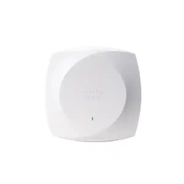
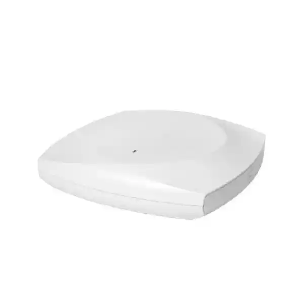
Cisco Wireless CW9174I Wi-Fi 7 Access Point
The Cisco Wireless CW9174I is an indoor, global-use Wi-Fi 7 access point engineered for organizations that need more spectrum flexibility, higher aggregate wireless capacity, multigigabit wired connectivity, advanced RF intelligence, integrated IoT capability, and a practical migration path between Cisco Catalyst and Meraki operating models. For enterprises in Dubai, Abu Dhabi, Sharjah and the wider United Arab Emirates, the CW9174I is particularly relevant where existing Wi-Fi 5, Wi-Fi 6 or Wi-Fi 6E infrastructure is reaching limits caused by dense client populations, high-throughput applications, collaborative workspaces, cloud applications, video, real-time communication, location-aware services and a growing number of wireless edge devices.
CW9174I at a glance
- Wi-Fi 7 / IEEE 802.11be enterprise indoor access point
- Up to 10 spatial streams in tri-band operation
- 2.4 GHz, 5 GHz and 6 GHz capability where locally permitted
- 5 Gbps multigigabit Ethernet uplink
- Integrated omnidirectional antennas
- Dedicated IoT and tri-band scanning radios
- Catalyst and Meraki management flexibility
- Global-use hardware model for simplified procurement
Why the Cisco CW9174I matters for modern UAE wireless networks
Enterprise wireless design in the UAE is no longer mainly about providing basic connectivity to laptops and phones. Modern offices may host collaboration suites, 4K and interactive video, virtual desktop sessions, real-time voice, cloud security agents, AI-assisted applications, wireless display systems, building-management sensors, handheld business terminals, asset tags, guest devices and dense populations of mobile endpoints. A wireless network that performed adequately several years ago can become constrained even when internet bandwidth has been upgraded, because the contention domain, channel plan, spatial capacity and access-layer switching architecture were never designed for the current application mix.
The CW9174I addresses this problem as a balanced enterprise Wi-Fi 7 platform rather than as a simple speed upgrade. Its design combines three client-serving frequency bands where permitted, up to ten spatial streams, 4×4 capability on the 5 GHz and 6 GHz radios, multigigabit Ethernet, a dedicated scan radio, integrated IoT functions and flexible management. The practical benefit is architectural headroom. A properly engineered deployment can distribute clients across more usable spectrum, reduce contention, improve airtime efficiency and retain operational visibility without requiring a separate sensor overlay for every RF-monitoring function.
For UAE organizations, the business case is strongest when wireless is treated as production infrastructure. Hospitality properties need consistent roaming and guest density. Healthcare locations need reliable coverage for clinical devices and staff mobility. Education environments face very high concurrent client counts. Retail sites must support point-of-sale, handheld, guest and IoT traffic. Corporate headquarters require stable application performance across meeting rooms and open-plan areas. The CW9174I can fit all of these scenarios, but the outcome depends on correct RF design, access-switch capability, PoE budgeting, controller architecture, licensing and country-specific radio settings. FourTeck approaches the product as part of a complete network design rather than as a standalone ceiling device.
Radio architecture: tri-band performance without ignoring real-world RF constraints
2.4 GHz radio
In the default tri-band arrangement, the 2.4 GHz client-serving radio operates as 2×2:2. This band remains important for legacy endpoints, certain handheld devices, IoT clients and coverage-sensitive applications, but it has relatively limited non-overlapping spectrum. In a well-designed enterprise network, 2.4 GHz is therefore normally treated as a compatibility and coverage layer rather than the primary high-throughput layer. The CW9174I also supports a dual-band configuration in which 2.4 GHz can operate as 4×4:4 while 5 GHz remains 4×4:4 and 6 GHz is disabled.
5 GHz radio
The 5 GHz client-serving radio supports 4×4 uplink and downlink MU-MIMO with four spatial streams. It supports 20, 40, 80 and 160 MHz channels, subject to regulatory channel availability and enterprise design choices. For many UAE deployments, 5 GHz will continue to carry a large percentage of business traffic because the installed client base is mature and because channel-reuse planning can be controlled more predictably than by simply enabling the widest possible channel everywhere.
6 GHz radio
The 6 GHz client-serving radio supports 4×4:4 operation and Wi-Fi 7 channel widths up to 320 MHz where allowed by the active country profile. This band creates valuable clean-spectrum opportunities for compatible clients, especially in modern high-capacity environments. UAE deployments should always validate current Cisco country support, software release requirements and local regulatory operation before assuming a specific 6 GHz channel plan. The correct design principle is to treat 6 GHz as a powerful capacity layer that must be engineered, not as a universal replacement for 5 GHz.
Dedicated scanning and IoT radios
The access point includes a dedicated tri-band scanning radio and a dedicated 2.4 GHz IoT radio. Separating scanning functions from the primary serving radios is valuable because RF visibility can be maintained without continuously sacrificing client-serving airtime. The integrated BLE and 802.15.4 capabilities also help organizations consolidate selected location, sensor and edge use cases into the wireless platform instead of automatically deploying an additional radio infrastructure.
Wi-Fi 7 capabilities: what the specifications mean in an enterprise design
Wi-Fi 7 is based on IEEE 802.11be and introduces several mechanisms that can improve throughput, efficiency and resilience when both infrastructure and clients support them. The CW9174I supports key Wi-Fi 7 capabilities including 4096-QAM, multilink operation, preamble puncturing, uplink and downlink OFDMA, multi-resource-unit mechanisms, larger compressed block acknowledgment structures, and channel widths up to 320 MHz on 6 GHz. These capabilities should be interpreted in the context of practical enterprise RF design rather than as guarantees that every client will achieve a headline PHY rate.
4096-QAM: Higher-order modulation can encode more data per symbol than 1024-QAM used in Wi-Fi 6. The tradeoff is that 4K QAM requires excellent signal quality and low interference. It is therefore most useful at shorter distances or in well-designed high-SNR cells. In a UAE office with concrete walls, reflective glass, dense partitions or large meeting spaces, client experience will still depend on AP placement and RF conditions. The correct takeaway is that 4K QAM provides additional peak efficiency under favorable conditions, not that it eliminates the need for a survey.
Multi-Link Operation: MLO is one of Wi-Fi 7’s most important architectural enhancements. Compatible clients can use multiple links across bands in ways that can improve throughput, latency or resiliency. The exact operational behavior depends on client implementation, software, network configuration and regulatory availability. For latency-sensitive enterprise applications, the ability to exploit multiple links can be more strategically important than raw speed because it creates more flexibility in how traffic uses available spectrum.
Preamble puncturing: Traditional wide-channel operation can be disrupted when part of the channel is affected by interference. Preamble puncturing allows supported systems to work around impaired portions of a wide channel rather than always abandoning the entire channel width. This is especially relevant in dense RF environments where perfectly clean contiguous spectrum may not always exist.
OFDMA and MU-MIMO: The CW9174I carries forward efficiency mechanisms from Wi-Fi 6 while extending the platform into Wi-Fi 7. OFDMA divides channel resources so multiple clients can be served more efficiently, while MU-MIMO uses multiple spatial streams to serve capable clients concurrently. These technologies improve the scheduler’s ability to use airtime productively, which is important in deployments with many active clients even when each individual client is not generating extreme throughput.
Detailed technical specification summary
| Category | Cisco CW9174I specification and design relevance |
|---|---|
| Product type | Enterprise indoor Wi-Fi 7 access point with integrated omnidirectional antennas and global-use hardware architecture. |
| Tri-band mode | 2.4 GHz 2×2:2, 5 GHz 4×4:4 and 6 GHz 4×4:4, providing up to ten spatial streams where 6 GHz is available. |
| Dual-band mode | 2.4 GHz 4×4:4 plus 5 GHz 4×4:4 with 6 GHz disabled, supporting up to eight spatial streams. |
| 5 GHz channels | 20, 40, 80 and 160 MHz channel widths, with channel availability governed by the selected country profile. |
| 6 GHz channels | 20, 40, 80, 160 and 320 MHz channel widths where regulatory and software support permit operation. |
| Wi-Fi 7 features | 4096-QAM, Multi-Link Operation, preamble puncturing, UL/DL OFDMA, Target Wake Time, BSS coloring, MRC, aggregation and other 802.11be functions. |
| Ethernet uplink | One 100M/1G/2.5G/5G multigigabit RJ-45 interface supporting PoE input. |
| Other interfaces | RJ-45 management console, USB 2.0 and 54V DC power jack. |
| Additional radios | Dedicated IoT radio plus dedicated tri-band scanning radio; integrated Bluetooth Low Energy and 802.15.4 capabilities. |
| Dimensions | Approximately 22.6 x 22.6 x 4.9 cm without mounting brackets. |
| Weight | Approximately 1.52 kg for the CW9174I. |
| Operating environment | Indoor operation from 0°C to 50°C and 10% to 90% relative humidity, noncondensing, subject to installation guidance. |
| Management | Cisco Catalyst wireless controller architecture and Meraki cloud-based management path, with platform-specific software requirements. |
5 Gbps multigigabit Ethernet: why the wired edge must be planned with the wireless upgrade
A common Wi-Fi upgrade mistake is to replace access points while leaving the wired access layer untouched. The CW9174I includes a single multigigabit RJ-45 interface that can negotiate 100 Mbps, 1 Gbps, 2.5 Gbps or 5 Gbps. This is important because a modern tri-band AP can move enough aggregate traffic that a legacy 1 GbE access-switch port becomes a structural limit. However, installing a 5 GbE-capable AP does not automatically produce a 5 Gbps end-user result. The switch must support the required mGig rate, the cable path must be suitable, PoE must be sufficient, upstream switch capacity must be dimensioned, and the client population must be capable of generating enough traffic to justify the link.
Cisco specifies Cat 5e, Cat 6 or Cat 6A cabling for multigigabit Ethernet support. In existing UAE buildings, cable quality can vary significantly, especially where horizontal cabling has been extended, patched repeatedly, bundled in high-temperature ceiling spaces or installed many years ago. A Wi-Fi 7 project should therefore include structured-cabling validation rather than assuming every existing drop will negotiate reliably at 5 Gbps. For critical sites, permanent-link certification and switch-port error monitoring can prevent intermittent issues that would otherwise be misdiagnosed as wireless faults.
The switch architecture also matters upstream. Twenty-four access points each connected at 5 Gbps do not mean the network requires 120 Gbps of guaranteed simultaneous uplink bandwidth, because wireless traffic is bursty and client usage varies. But the aggregation design should be based on realistic peak utilization, application behavior, uplink redundancy, oversubscription policy and growth. FourTeck’s UAE IT services practice can align AP deployment with switching, VLAN, PoE, cabling and core-uplink requirements so the wireless refresh does not merely move the bottleneck one layer deeper into the network.
PoE planning: full feature operation depends on power class
Power planning is one of the most important parts of a CW9174I deployment. With 802.3bt Class 5 power or the supported 54V DC option, the access point can run full tri-band 2×2 on 2.4 GHz plus 4×4 on 5 GHz and 4×4 on 6 GHz while maintaining a 5 Gbps Ethernet link and up to 9W USB output. Cisco lists a maximum PoE requirement at the powered device of 37W for that tri-band configuration. In dual-band operation with 4×4 on 2.4 GHz and 4×4 on 5 GHz, Cisco lists a maximum requirement of 32W under the same power class.
The access point can operate on 802.3at PoE+, but capabilities are adjusted. Under PoE+, Cisco documents a 2.5 Gbps Ethernet link rather than 5 Gbps and USB output reduced to 2.5W, while the tri-band serving-radio arrangement can remain available. With 802.3af PoE, operation is heavily degraded: Cisco documents a 1×1 2.4 GHz radio, no 5 GHz or 6 GHz serving radio, 1 Gbps Ethernet and no USB. This makes it clear that legacy PoE should not be considered an acceptable steady-state design for an enterprise Wi-Fi 7 rollout.
For a 48-port access switch, a designer should not simply multiply the maximum AP draw by 48 and stop there. The correct method considers the number of powered devices, other PoE consumers such as phones and cameras, switch power-supply redundancy mode, power-supply capacity, expected radio configuration, USB use, environmental derating where applicable, and failover behavior after a power-supply fault. A switch may have enough ports but insufficient PoE budget to operate every connected AP at the desired class.
Power redundancy deserves equal attention. If an access switch loses one PSU and falls back to a smaller shared PoE budget, access points may enter a degraded state exactly when the organization is already dealing with an infrastructure incident. Critical campuses should calculate the surviving PoE budget under a single-PSU failure and confirm whether business-priority wireless areas remain fully powered. This is an engineering question, not simply a bill-of-materials question.
Catalyst or Meraki: one hardware platform, two operational models
One of the most strategically useful aspects of the Cisco Wireless 9174 generation is the unified hardware direction. The CW9174I is designed as a global-use access point that can participate in Cisco’s controller-based Catalyst architecture or the Meraki cloud-managed stack, depending on deployment choice and supported software. This helps simplify inventory because the same core AP hardware can fit organizations that prefer centralized enterprise controller operations as well as organizations that prioritize cloud administration.
Catalyst operating model: Enterprises using Cisco Catalyst 9800 Series Wireless Controllers can integrate the CW9174I into a policy-rich controller architecture suited to large campuses, complex segmentation, SD-Access integration, advanced assurance and tightly controlled operational change management. Cisco documents IOS XE 17.18.2 or later for the CW9174 series, and Catalyst Center can provide analytics, assurance, automation, power-management visibility and lifecycle workflows when deployed in a compatible architecture.
Meraki operating model: Organizations that prioritize cloud-based operations can use the Meraki management path, with Cisco documenting Meraki firmware 32.1.5 or later for the CW9174 series. This model can be attractive for distributed organizations with many UAE branches, retail sites or operational locations where centralized cloud visibility and streamlined configuration are priorities.
The selection should be based on the broader operating model rather than on the AP alone. Consider controller investments, administrator skill sets, change-control requirements, WAN resilience, telemetry needs, integration with identity and segmentation, branch scale, licensing strategy and long-term platform direction. FourTeck can help customers compare the two approaches and design a migration path that does not force an unnecessary rip-and-replace of surrounding infrastructure.
RF design methodology for CW9174I deployments
A high-performance access point cannot compensate for incorrect placement. UAE commercial interiors often combine glass, gypsum partitions, reinforced concrete, metalized films, decorative cladding, lift cores, dense furniture and mechanical-service areas. Each material affects RF propagation differently, and 6 GHz generally has different coverage characteristics from 2.4 GHz and 5 GHz. A design that places APs only according to floor area can therefore create inconsistent coverage, excessive co-channel contention or insufficient high-band signal at client locations.
1. Define application targets
Start with the experience requirement. Voice, collaboration video, warehouse scanners, guest internet and general office traffic do not need identical RSSI, SNR, roaming or latency targets. Capacity and coverage objectives should be explicit before drawing AP locations.
2. Model attenuation
Use accurate floor plans and realistic wall attenuation assumptions. Predictive design is useful, but construction data should be validated on site because decorative materials and hidden structures can produce unexpected losses.
3. Plan for capacity
Calculate active clients per area, expected concurrency, application demand and airtime consumption. A 300-seat conference facility has a different design profile from a 300-seat office even when both occupy similar floor area.
4. Validate after installation
Perform post-deployment verification. Check coverage, roaming, channel reuse, retries, noise, utilization, uplink negotiation and client behavior. The final RF plan should be based on measured reality, not just the predictive drawing.
Wi-Fi 7 also changes channel-planning choices. A 320 MHz channel can deliver enormous peak capacity, but very wide channels reduce the number of independent channels available for reuse. In dense environments, several narrower cells can often produce more aggregate capacity and more predictable contention behavior than one very wide channel per AP. The correct width is therefore determined by density, client capability, available spectrum and interference—not by selecting the largest number in the data sheet.
Integrated antennas and installation considerations
The CW9174I uses integrated omnidirectional antennas, making it a strong fit for conventional indoor ceiling deployments where a broad, relatively symmetric coverage pattern is desired. Cisco specifies peak integrated antenna gains around 5 dBi for 2.4 GHz, 5 dBi for 5 GHz and 6 dBi for 6 GHz, with a dedicated IoT antenna as part of the platform. Integrated antennas simplify installation because there are no external antenna cables, connectors or antenna-position calculations to manage for ordinary office use cases.
That simplicity does not mean the AP can be installed anywhere. Ceiling height, orientation, obstructions, metal services, access hatches, ducts, cable trays and aesthetic concealment all influence performance. Mounting an AP above a metal suspended ceiling or inside a closed cabinet can substantially alter the RF pattern and reduce effective coverage. Similarly, mounting high above an open atrium may create a large cell that looks impressive on a basic coverage map but produces poor client uplink behavior because handheld endpoints transmit at much lower power than the AP.
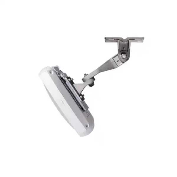
The device measures approximately 22.6 x 22.6 x 4.9 cm without the mounting bracket and weighs about 1.52 kg. Mechanical planning should confirm ceiling support, bracket compatibility, cable bend radius and safe service access. The access point should be positioned where technicians can reach it without unnecessary disruption, but serviceability should not compromise RF placement.
For specialized antenna requirements—such as warehouse aisles, unusual ceiling heights, selective directional coverage or RF isolation—the external-antenna CW9174E may be more appropriate. The integrated-antenna CW9174I is best when the desired pattern aligns with an omnidirectional indoor cell. Choosing between I and E variants should happen during design, not after the installation team encounters a coverage geometry problem.
Security capabilities for enterprise wireless access
The CW9174I supports modern enterprise wireless security mechanisms including WPA2, WPA3, 802.1X-based access control, Enhanced Open/OWE and strong AES-based cipher suites such as GCMP and CCMP variants supported by the Cisco platform. It also supports multiple EAP methods commonly used in enterprise authentication environments. These features provide the building blocks for secure access, but the security outcome still depends on identity architecture, certificate management, RADIUS policy, endpoint posture, segmentation and monitoring.
For corporate SSIDs, certificate-based authentication with EAP-TLS is often preferred where the endpoint-management process can support certificate issuance and lifecycle management. EAP-TLS reduces dependence on reusable passwords and can provide a strong device-identity foundation. Guest access should normally be separated from corporate resources through policy and routing boundaries, while IoT devices may require their own segmentation strategy because many embedded clients cannot support the same authentication methods as managed laptops.
A dedicated scanning radio is also operationally valuable. Wireless threat detection, rogue-device visibility, RF monitoring and assurance can be performed without dedicating a primary serving radio entirely to scanning. This can help security and network teams maintain visibility while preserving service capacity. The exact feature set depends on the selected Catalyst or Meraki software stack and licensing level.
Security should extend beyond the air interface. The switch port connected to the AP, controller connectivity, management-plane access, administrator authentication, firmware lifecycle, API credentials and logging integrations all belong to the same security boundary. FourTeck can align wireless policy with firewall segmentation and broader network-security controls through the Firewall Dubai practice when the wireless upgrade is part of a larger zero-trust or segmentation initiative.
Client capacity and density: why the theoretical maximum is not a sizing target
Cisco documents a scale figure of up to 768 clients for the CW9174 platform, with 256 clients per radio in the referenced deployment guidance. This number describes platform capability, not a recommended design target for every production cell. An access point with hundreds of associated devices can still provide a poor user experience if a large percentage of those devices are actively transmitting, using legacy rates, consuming airtime with multicast traffic, roaming poorly or competing on a congested channel.
Professional sizing therefore distinguishes between associated clients and active clients. A training room may have 120 devices associated but only 30 simultaneously exchanging meaningful traffic. A conference hall may have 500 associated devices with short bursts from many users. A call center may have fewer devices but continuous voice and desktop traffic. A hospital may have moderate user density but strict mobility requirements and a mix of specialized wireless endpoints. Each pattern drives a different airtime model.
Client capability also matters. A modern Wi-Fi 7 laptop can take advantage of capabilities that an older 802.11ac handset cannot. The network must preserve backward compatibility while preventing old clients from dominating airtime. Minimum data-rate policies, band steering, SSID design, client-driver management and periodic endpoint refresh all influence realized capacity. The AP can support earlier 802.11 generations, but backward compatibility should not become an excuse to keep inefficient radio settings indefinitely.
For high-density spaces, AP count should be based on the expected airtime demand per cell and acceptable channel reuse rather than simply increasing transmit power. More power can make cells larger, but it does not make client devices transmit more strongly. In many designs, reducing AP transmit power and deploying a carefully planned number of smaller cells produces better bidirectional performance and roaming than attempting to cover a large area from a small number of very powerful APs.
Roaming, voice and real-time application design
Seamless roaming is a system behavior involving access points, controllers, authentication services and clients. Installing newer APs improves the radio platform, but it does not guarantee that every handset will roam at the ideal moment. Most Wi-Fi clients make their own roaming decisions, and poorly tuned client drivers can remain attached to a distant AP even when a stronger neighbor is available. An enterprise design must therefore create consistent coverage overlap, reasonable cell boundaries and compatible fast-roaming settings.
Voice and interactive video place additional demands on latency, jitter and packet loss. These applications often expose wireless weaknesses that general web browsing hides. For a voice-heavy UAE deployment, design targets should consider minimum signal level, signal-to-noise ratio, channel utilization, retry rate and roaming delay. Quality-of-service markings should be preserved through the wireless controller, switch fabric, WAN and firewall path where appropriate so that traffic classification does not stop at the AP.
Wi-Fi 7 features such as Multi-Link Operation may improve future latency and resiliency for supported clients, but deployment teams should test the actual client fleet. Enterprise applications rarely refresh every endpoint simultaneously. A new CW9174I network may therefore serve a mixed population of Wi-Fi 5, Wi-Fi 6, Wi-Fi 6E and Wi-Fi 7 devices for years. Designing only for the newest client can create surprising behavior for the majority of users.
A pilot is particularly valuable for contact centers, healthcare voice systems, logistics handhelds and other latency-sensitive applications. The pilot should reproduce actual roaming paths, power-saving states, authentication behavior and busy-hour utilization rather than testing a single speed measurement near an AP.
IoT, BLE and edge-application potential
The CW9174I is not only a client Wi-Fi access point. Its integrated Bluetooth Low Energy radio, 802.15.4 capability, dedicated IoT radio, USB interface and application-hosting support create a broader edge platform. Cisco specifies BLE 5.3 support with a future software upgrade path toward BLE 6, subject to software support. These features can support location-aware applications, asset tracking, wayfinding, telemetry collection and other IoT workflows when paired with the appropriate Cisco software and application ecosystem.
The USB 2.0 port can provide up to 9W under full power conditions, allowing supported modules to be integrated without an entirely separate power system. Application hosting can also allow containerized functions to execute at the edge on supported configurations. The design value is consolidation: rather than installing multiple independent overlays for wireless access, scanning and certain IoT functions, an enterprise may be able to use the access-point estate as a distributed edge platform.
This is particularly relevant to retail, healthcare, logistics and smart-building use cases in the UAE. A retailer may use wireless infrastructure for customer connectivity, handheld devices and location analytics. A hospital may combine staff connectivity with asset awareness. A commercial building may support occupant applications and selected sensor integrations. However, every IoT design should define data ownership, application lifecycle, security boundaries, battery behavior, radio coexistence and support responsibility before deployment.
Organizations should also confirm whether the specific IoT use case requires licensed software, cloud services, third-party integration or dedicated gateway functionality. The presence of an integrated radio is an enabler, not a complete solution by itself. FourTeck can incorporate these dependencies into the architecture and bill of materials so the project scope reflects the end-to-end application rather than only the AP hardware.
UAE regulatory and 6 GHz planning
The CW9174I uses Cisco’s global-use hardware approach, which removes the need to procure a traditional country-specific regulatory-domain hardware variant. Cisco lists the United Arab Emirates under the CW917x country support matrix. Even with global hardware, radio behavior is still governed by the configured country, supported software release and regulatory approvals. This distinction is important: global hardware simplifies logistics, but it does not override national spectrum rules.
For 6 GHz, Cisco explicitly notes that availability is country-specific and can require a software release later than the base release. The safest procurement and deployment method is to validate the current Cisco country support and channel availability for the exact software train selected for the project. This should occur before the final RF design is locked, because the number of usable 6 GHz channels affects channel-width strategy, capacity assumptions and AP reuse.
Design documents should separate hardware capability from regulatory operation. The CW9174I hardware supports 6 GHz and channel widths up to 320 MHz, but the live network must use only the frequencies and power levels permitted by the UAE profile in the deployed software. A site survey can still model future 6 GHz coverage, but the implementation plan should be based on the legally available channel set at commissioning time.
This approach protects customers from two common mistakes: purchasing region-bound stock that complicates support, and assuming a specification-sheet channel plan that does not match the country profile. FourTeck can verify the planned controller or Meraki software path, power requirements and local operating assumptions before rollout.
Migration from Wi-Fi 5, Wi-Fi 6 and Wi-Fi 6E
A CW9174I deployment can be introduced as a staged upgrade rather than a one-day replacement of every access point. Cisco supports interoperability with earlier client generations, and hybrid AP estates may be practical while organizations refresh floors, branches or buildings in phases. The migration plan should consider controller software compatibility, switch PoE, mGig readiness, mounting hardware, RF channel plans and whether older APs will remain in the same mobility domain during transition.
From Wi-Fi 5: The jump is significant because the network gains OFDMA, newer MU-MIMO behavior, BSS coloring, WPA3 support and the broader improvements carried through Wi-Fi 6 and Wi-Fi 7. Many Wi-Fi 5-era switches also have 1 GbE and older PoE budgets, so the wired edge is often the largest migration dependency.
From Wi-Fi 6: Organizations already have modern OFDMA and MU-MIMO foundations, but Wi-Fi 7 adds 4K QAM, MLO, preamble puncturing and wider 6 GHz channel capability. The business case should focus on density, spectrum, latency, future client lifecycle and infrastructure standardization rather than on replacing functional Wi-Fi 6 solely for a theoretical peak-speed gain.
From Wi-Fi 6E: The organization already has 6 GHz experience, so the migration decision becomes more about Wi-Fi 7 efficiency, management architecture, higher-order modulation, MLO, preamble puncturing and long-term support. Existing 6 GHz RF plans can provide a useful baseline but should still be recalculated because client mix and channel strategy may change.
A phased migration should include pilot areas, success criteria and rollback planning. Suitable pilot zones include collaboration-heavy floors, executive meeting areas, high-density training rooms or a representative branch. Measure user experience, channel utilization, client roaming, uplink rate, PoE state and controller health before repeating the design across the wider estate.
Deployment scenarios across the UAE
Corporate offices
Open-plan floors, video meeting rooms, executive spaces and hot-desking areas benefit from predictable 5 GHz capacity, selective 6 GHz use for newer clients and careful cell sizing. The CW9174I’s integrated antenna format is well suited to conventional ceiling layouts.
Hospitality
Hotels and serviced apartments require guest connectivity, staff devices, voice, IPTV-related workflows and operational systems. RF design must account for room walls, corridors and high-density public spaces; a single AP placement rule cannot cover both guestrooms and ballrooms.
Education
Classrooms, lecture halls and common areas often produce sharp concurrency peaks. Capacity planning should be based on students per room, active-device ratio, online learning applications and assessment periods rather than building area alone.
Healthcare
Clinical mobility, voice, medical devices, guest traffic and asset use cases demand both coverage and policy separation. Change control, validation and roaming tests are normally more important than maximum benchmark throughput.
Retail
Point-of-sale, scanners, handheld inventory devices, staff applications, digital engagement and guest Wi-Fi can coexist on the same physical RF infrastructure while remaining logically segmented through SSIDs, VLANs and policy.
Warehousing and logistics offices
The CW9174I fits normal offices and operational rooms, while specialized warehouse aisles or high ceilings may justify the external-antenna CW9174E. A mixed I/E design can be more effective than forcing one AP form factor across every environment.
SSID architecture and segmentation
Cisco documents support for up to 16 SSIDs per band on the CW9174 platform, but this does not mean a production design should advertise sixteen networks everywhere. Each broadcast SSID adds management overhead and increases airtime consumed by beacons and associated control traffic. A smaller number of well-designed SSIDs is usually preferable. The objective is to map user and device groups to policy while keeping the RF environment efficient.
A typical enterprise architecture may use a corporate SSID, a guest SSID and one or more device-specific onboarding mechanisms, with segmentation enforced through identity and policy. IoT should not automatically receive its own SSID for every device category; policy groups, dynamic VLAN assignment or software-defined segmentation can often reduce SSID sprawl. The exact mechanism depends on the Catalyst or Meraki architecture and the identity platform.
Guest traffic should be isolated from internal networks and should have bandwidth, DNS, content and security controls appropriate to the organization. Corporate traffic may require direct access to internal resources or cloud security services. Voice devices may need optimized QoS behavior. Building systems may require east-west isolation. These requirements should be documented as a policy matrix before AP configuration begins.
FourTeck can align wireless segmentation with upstream routing and security policy using the broader FourTeck UAE network portfolio. This is especially useful for customers who want the Wi-Fi 7 project to serve as a trigger for simplifying VLANs, modernizing authentication or introducing role-based access controls.
Performance expectations: reading the PHY rate correctly
Cisco cites aggregate PHY data rates up to roughly 17.5 Gbps for the tri-band Wi-Fi 7 configuration under idealized conditions that combine 4×4 320 MHz operation on 6 GHz, 4×4 160 MHz on 5 GHz and 2×2 20 MHz on 2.4 GHz. This is a useful indication of radio capability, but it is not an application-throughput guarantee. PHY rates include protocol overhead, and real traffic is affected by contention, retransmissions, client spatial-stream count, channel width, signal quality, encryption, scheduler behavior and the wired path.
Most enterprise clients are two-spatial-stream devices rather than four-stream devices. A four-stream AP still provides major value because it can use MU-MIMO, spatial diversity and capacity mechanisms across multiple endpoints, but a single 2×2 laptop will not consume the full 4×4 radio capability. Similarly, a client that supports only an 80 MHz channel cannot take advantage of a 320 MHz 6 GHz channel even if the AP advertises it.
Performance testing should therefore use representative clients and applications. A good acceptance test includes several simultaneous clients at different distances, uplink and downlink traffic, roaming, latency and packet-loss measurements. Testing only one flagship laptop beside the AP produces a benchmark that may be technically impressive but operationally unrepresentative.
The 5 Gbps Ethernet interface also establishes a practical wired ceiling for aggregate traffic through one AP. This is not a defect; it is a deliberate balance between radio capacity, traffic behavior, cost and switch architecture. The objective is predictable user experience across many clients, not a claim that every theoretical wireless bit must exit the AP at the same instant.
Switching and core-network readiness checklist
Before purchasing a large CW9174I quantity, the access layer should be audited. Confirm which switch ports support 2.5G or 5G mGig, whether the switch software supports the desired AP behavior, how much Class 5 PoE power is available, how uplinks are provisioned, whether link aggregation or redundant core paths meet availability goals, and whether existing patch panels and horizontal cabling can sustain multigigabit operation.
Core and distribution design should be reviewed for aggregate wireless growth. A Wi-Fi 7 refresh may increase traffic because users actually consume more bandwidth when the access layer stops being the bottleneck. Cloud backups, video, virtual desktops and large software updates can quickly raise east-west and north-south usage. WAN and internet circuits may also need to be reconsidered in branches where the local access network becomes substantially faster.
DHCP, DNS and authentication infrastructure must scale with the client population. Wireless outages attributed to access points are often caused by exhausted DHCP scopes, delayed RADIUS responses, DNS failure, incorrect VLAN trunking or firewall policy. An upgrade project should therefore include service dependencies in the commissioning checklist.
For campus networks, consider the failure domain. If a single switch stack powers every AP on a floor, a switch-stack outage removes all wireless coverage from that area. Strategic AP distribution across redundant switch systems can improve resilience. The correct design depends on building cabling, network architecture and business continuity requirements.
Operational assurance, troubleshooting and lifecycle management
A production Wi-Fi network should be operated through telemetry and trends, not only through user complaints. The CW9174I’s integration with Cisco management platforms enables administrators to monitor client experience, RF conditions, channel utilization, retries, onboarding failures, software status and other operational indicators. Catalyst Center can add assurance and analytics capabilities in supported deployments, while Meraki provides cloud-based dashboards and operational workflows for organizations using that stack.
A useful operations baseline records normal values before problems occur. Capture client count by AP, average channel utilization, retry rates, top applications, uplink negotiation rate, radio power, channel assignments and authentication latency. During an incident, these baselines help distinguish a real RF change from a broader network or application issue.
Software lifecycle management is equally important. Wi-Fi 7 is an evolving ecosystem in which client drivers, AP firmware and controller software receive ongoing improvements. Organizations should maintain validated software versions, test updates in a representative pilot group and review release notes before broad rollout. A regulated or critical environment may need a formal maintenance window and documented rollback path.
Spare strategy should also be considered. The global-use hardware model can simplify spares because a common CW9174I unit can fit supported geographies and management models, but licensing, software and country configuration still have to be handled correctly. Cisco provides a limited lifetime hardware warranty for the series, with terms that should be verified for the exact purchasing channel and support contract. Customers requiring faster incident response may still choose Cisco support services and locally held spare stock.
Energy use and sustainable network operations
Cisco documents typical PoE+ power consumption for the CW9174I at approximately 15.9W under its stated test conditions, with idle consumption around 12.4W plus or minus the documented variance. Actual use changes with radio activity, Ethernet rate, USB use, traffic and environmental conditions. For a large deployment, even modest per-AP savings can become meaningful across hundreds or thousands of devices.
Cisco includes AP Power Save capabilities that can reduce energy consumption by disabling selected features during periods when full capacity is not required. This can be relevant in offices with predictable off-hours, schools outside teaching periods or branches that close overnight. Energy features should be applied carefully in 24×7 environments, because building systems, security teams and cleaning staff may still require wireless access outside normal business hours.
Switch-side port scheduling can complement AP power policies in compatible environments, but abrupt PoE removal eliminates all service from that AP and may not suit critical locations. A better plan may selectively reduce radio features rather than remove power completely. Monitoring actual power consumption before and after policy changes helps validate savings.
Hardware reuse is another sustainability consideration. Cisco has designed the platform with compatibility for existing mounting approaches in many upgrade situations, which can reduce installation waste and labor. Customers should verify actual bracket compatibility for the current estate before assuming every legacy mount can be reused, but the principle supports smoother refresh projects.
Procurement guidance for UAE organizations
Wireless procurement should include more than the access-point part number. A complete CW9174I bill of materials can require mounting hardware, appropriate PoE switching, power injectors or DC supplies for exceptional cases, controller capacity, licenses, support coverage, optics for switch uplinks, patching and possibly new structured cabling. The exact BOM depends on whether the deployment uses Catalyst controllers or Meraki cloud management and whether the site already has compatible switching.
The global-use CW9174I product architecture simplifies regional stock management, but organizations should still verify local approval, country support, software release and intended 6 GHz operation before rollout. Procurement teams should also distinguish genuine Cisco channel stock from unsupported gray-market hardware. Support entitlement, warranty handling and replacement logistics can depend on the source of the equipment and service contract.
Lead time matters for large UAE deployments. Access points, switches, optics and licenses may have different availability windows. Ordering APs before validating PoE switch availability can leave hardware sitting unused, while ordering switches without a final RF count can create port shortages. A coordinated project schedule reduces these dependencies.
For organizations with regional operations beyond the UAE, FourTeck can also coordinate technology requirements through its global FourTeck network. The objective is to standardize core architecture where practical while respecting each country’s spectrum rules, import requirements and deployment conditions.
When the CW9174I is the right access point—and when to consider another model
The CW9174I is a strong fit for moderate-to-high-density indoor environments that need more than entry-level Wi-Fi 7 capability but do not require the maximum radio and wired specifications of the highest-end Cisco models. Its 4×4 capability on 5 GHz and 6 GHz, 5 GbE interface, integrated omnidirectional antennas and IoT functions make it particularly suitable for enterprise offices, education, healthcare, retail and hospitality spaces with substantial client populations.
Consider the CW9174E instead when the RF design requires external directional or specialized antennas. Consider higher-end Wi-Fi 7 models when extremely dense venues, advanced location functions, dual high-speed uplinks or additional radio resources justify the extra hardware. Consider lower-tier models where client density, application demand and wired infrastructure do not warrant the CW9174I’s capacity.
The most cost-effective product is not always the least expensive AP. If an undersized model requires more APs, more switch ports and more cable runs, the installed project can cost more than a correctly sized higher-capacity design. Conversely, deploying premium APs everywhere can waste budget if branch locations have ten users and a 500 Mbps WAN link. Sizing should therefore optimize the whole system.
FourTeck can compare the CW9174I against adjacent Cisco options using floor plans, user counts, existing switch inventories and application requirements. This avoids selection based only on model hierarchy and ensures the chosen AP aligns with the real constraints of the site.
Reference architecture: branch, campus and multi-site deployment patterns
A branch deployment may use a compact set of CW9174I access points connected to mGig PoE access switches with centralized cloud management through Meraki or controller connectivity back to a corporate Cisco architecture. The design priority is often operational simplicity: standardized templates, remote visibility, resilient WAN behavior and minimal local technical intervention. Branch AP count is driven by room geometry and client demand, not by a fixed number per square meter.
A campus deployment typically adds more layers. Access switches may be stacked or redundant, with multiple uplinks to distribution. Catalyst 9800 controllers can centralize policy, and Catalyst Center can provide assurance and automation. RF design must coordinate channel reuse across floors and adjacent buildings. Authentication and segmentation are usually integrated with enterprise identity services. A campus may also use mixed AP models so ordinary offices receive CW9174I units while auditoriums, outdoor areas or warehouses use other antenna and radio configurations.
A multi-site enterprise may adopt a standardized hardware and licensing policy while still allowing site-specific RF designs. This provides the best of both approaches: centralized operations without forcing identical AP counts and channel widths across completely different buildings. Standardization should cover software versions, naming, SSID policy, authentication, logging, switch configuration and change control. Site variation should be allowed for RF geometry, user density and local regulatory needs.
The CW9174I’s global-use architecture helps this model because one core hardware PID can support many deployment regions. The country configuration and software stack still determine actual radio behavior, so regional governance remains essential. Multi-country customers should maintain a regulatory matrix that maps software version, country code, permitted bands and support status for every operating territory.
Implementation sequence for a controlled Wi-Fi 7 rollout
Discovery: Collect current floor plans, AP inventory, switch models, PoE budgets, controller versions, licenses, VLANs, authentication services, internet circuits, user counts and known wireless complaints. Export current RF metrics if available. Identify business-critical areas where downtime or poor roaming would have high impact.
Design: Build the target RF plan, determine AP count and model mix, define channel-width strategy, select the Catalyst or Meraki operating model, calculate switch and PoE requirements, and document SSIDs and segmentation. Validate UAE regulatory and software assumptions before locking the 6 GHz design.
Pilot: Install a representative sample of CW9174I units. Confirm 5 GbE or 2.5 GbE negotiation as planned, validate PoE state, test authentication, roam representative clients and measure performance under realistic load. Record exceptions before scaling.
Rollout: Stage hardware, licenses and configurations. Upgrade switch code if required. Install APs in controlled batches and monitor adoption, channel selection, client experience and controller health after each change window. Maintain rollback paths for areas supporting critical operations.
Optimization: Perform post-deployment validation after the building returns to normal occupancy. Adjust transmit power, channels, minimum rates or AP locations based on measured data. Compare before-and-after KPIs and transfer operational documentation to the network team.
Common Wi-Fi 7 deployment mistakes to avoid
Using 320 MHz everywhere
The widest channel maximizes peak PHY potential but can reduce channel reuse. Dense networks often benefit from narrower channels and more independent cells. Width should be a capacity-design decision.
Ignoring PoE mode
A CW9174I powered by legacy PoE can enter a severely restricted state. Confirm 802.3bt Class 5 if full 10-stream, 5 GbE and 9W USB operation is required.
Assuming old cabling is fine
mGig negotiation depends on cable condition. Test legacy links, especially long runs, heavily patched circuits and cable bundles exposed to high temperatures.
Sizing by floor area only
Coverage and capacity are different problems. User density, construction materials, application demand and roaming targets are required inputs.
Overloading the SSID count
The platform supports many SSIDs, but every broadcast network consumes airtime. Consolidate policy through identity and segmentation where practical.
Skipping post-install validation
Predictive designs are assumptions until measured. Verify RF, client roaming, retries, uplink rate, authentication and PoE behavior after deployment.
FourTeck UAE engineering and deployment support
A Cisco CW9174I project can range from a small office refresh to a multi-building enterprise rollout. FourTeck can support discovery, RF design, access-switch readiness, bill-of-material validation, controller integration, Meraki deployment, licensing alignment, structured cabling coordination, implementation, migration and post-deployment optimization. The engagement can start with a single site and expand into a standard architecture for multiple UAE branches.
For organizations modernizing more than wireless, the project can be integrated with switching, firewall, server, voice and broader infrastructure requirements. This reduces the risk of disconnected projects in which every technology is upgraded independently without considering shared dependencies such as VLANs, DHCP, identity, PoE, uplinks and monitoring.
FourTeck also supports organizations evaluating lifecycle strategy. Not every site needs Wi-Fi 7 immediately. Some locations may remain on Wi-Fi 6 while high-density or strategic areas move to CW9174I first. A staged roadmap can balance budget, client refresh cycles and operational capacity while still establishing a consistent target architecture.
To review other enterprise infrastructure and networking capabilities, visit FourTeck UAE, explore specialized IT services in the UAE, or use the FourTeck global site for broader regional requirements.
Frequently asked technical questions
Is the Cisco CW9174I a true Wi-Fi 7 access point?
Yes. It is an IEEE 802.11be Wi-Fi 7 enterprise access point supporting features including 4096-QAM, Multi-Link Operation, preamble puncturing, OFDMA and up to 320 MHz channels in 6 GHz where allowed.
How many spatial streams does the CW9174I support?
Up to ten in tri-band mode: two on 2.4 GHz and four each on 5 GHz and 6 GHz. It can also run dual-band with four streams on 2.4 GHz and four on 5 GHz while 6 GHz is disabled.
Does it require a 5 GbE switch port?
The AP supports 5 GbE, but it can negotiate lower rates. Full 5 GbE operation requires a compatible mGig switch port and sufficient power. Under PoE+ Cisco documents 2.5 GbE operation, while legacy 802.3af PoE limits the AP substantially.
Can it work with Cisco Catalyst and Meraki?
Yes. The platform is part of Cisco’s unified hardware direction and supports controller-based Catalyst or Meraki cloud-managed deployments, subject to the required software and licensing.
Is 6 GHz available in the UAE?
Cisco lists the UAE in its CW917x country support matrix, but 6 GHz availability remains dependent on current country approval and software release. The exact deployed release and channel profile should be checked during project design.
What PoE should be planned?
For full 10-stream tri-band operation, 5 GbE and 9W USB, plan for 802.3bt Class 5 or the supported DC power option. PoE+ can run the AP with reduced Ethernet and USB capability, while 802.3af produces a heavily degraded mode.
Is the CW9174I suitable for warehouses?
It can suit warehouse offices and some open operational spaces, but narrow aisles, very high ceilings or directional-coverage requirements may be better served by the external-antenna CW9174E or another specialized model.
Does a Wi-Fi 7 deployment require Wi-Fi 7 clients?
No. The AP remains interoperable with earlier supported Wi-Fi generations. However, only Wi-Fi 7 clients can use Wi-Fi 7-specific mechanisms, and the actual benefit depends on client capability, drivers and RF conditions.
Decision recap: what a technically sound CW9174I purchase should achieve
The Cisco Wireless CW9174I is most valuable when its capabilities are matched by the surrounding architecture. A successful deployment should deliver not only a newer radio standard, but also cleaner spectrum usage, adequate wired uplink capacity, correct PoE power, secure identity-based access, operational telemetry and a migration path that fits the organization’s management model.
Choose CW9174I when
You need integrated omnidirectional antennas, moderate-to-high client density, 4×4 capacity on 5 and 6 GHz, a 5 GbE uplink, enterprise IoT capabilities and Catalyst or Meraki flexibility.
Upgrade the access layer when
Existing switches lack 5G mGig, cannot provide adequate Class 5 PoE, have limited uplink bandwidth, or use old cabling that cannot reliably sustain multigigabit Ethernet.
Validate before rollout
Confirm UAE country support, software release, 6 GHz operating profile, controller or Meraki licensing, AP count, PoE budget, cabling, switch uplinks and representative client behavior.
Measure success by
User experience, retries, channel utilization, roaming quality, authentication reliability, application latency, uptime and operational simplicity—not by a single speed test next to the AP.
Quotation input checklist for Cisco CW9174I UAE projects
Providing the following information allows FourTeck to prepare a more accurate bill of materials, licensing plan and deployment scope. Where exact data is unavailable, approximate figures can be used for the first design pass and refined during discovery.
Number of locations, floor areas, ceiling types, construction materials and any high-ceiling or outdoor-adjacent spaces.
Expected concurrent users, number of devices per person, IoT devices, phones, scanners and high-density rooms.
Voice, Teams or Webex, video, VDI, cloud apps, guest access, POS, medical devices, real-time systems and large file transfers.
Switch model, available mGig ports, PoE standard, total power budget, PSU redundancy and uplink speeds.
Existing Catalyst 9800 controller, Catalyst Center, Meraki organization, or requirement for a new management architecture.
RADIUS, ISE, certificates, guest portal, VLANs, firewall segmentation and any compliance or audit requirements.
Current AP models, desired replacement window, coexistence requirements, downtime limits and priority pilot areas.
Hardware supply only, remote configuration, on-site installation, RF survey, cabling, managed support, spares or full turnkey deployment.
Plan the CW9174I as a complete wireless system, not an isolated device
FourTeck can help determine the correct AP quantity, RF design, Catalyst or Meraki management path, licensing, switch and PoE requirement, cabling readiness, security segmentation and UAE deployment sequence. The same engagement can include post-install validation so the delivered wireless network is measured against defined performance and coverage objectives.
For complex projects, share floor plans, current switch models, approximate user counts and the existing Cisco wireless platform. This allows the quotation to distinguish hardware, licenses, mounting, survey, implementation and migration work instead of hiding critical dependencies inside a single line item.
Recommended next steps
- Confirm site and user requirements.
- Audit mGig switching and Class 5 PoE.
- Validate controller or Meraki software path.
- Complete predictive RF design and pilot.
- Confirm UAE 6 GHz profile at deployment release.
- Roll out in measured stages with post-install optimization.

Reviews
There are no reviews yet.