
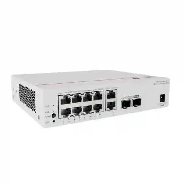
Huawei CloudEngine S5751-L8P2PN2J-RUA
A fanless, multigigabit PoE+ remote-unit switch engineered for streamlined campus access, compact edge locations and centrally operated enterprise networks.
For Dubai and UAE projects, the S5751-L8P2PN2J-RUA is especially relevant where network designers need more than ordinary Gigabit access at the endpoint, but do not want to place a full conventional access switch in every corridor, floor, classroom zone, guest-room cluster or branch edge. Its combination of eight Gigabit copper interfaces, two additional 2.5G PoE+ copper interfaces and two 2.5GE SFP uplinks makes it a practical bridge between legacy endpoint requirements and newer Wi-Fi, camera, collaboration and IoT devices that can benefit from multigigabit bandwidth.
What the S5751-L8P2PN2J-RUA is designed to do
The Huawei CloudEngine S5751-L8P2PN2J-RUA belongs to the CloudEngine S5751-L family of remote-unit switches. In Huawei’s streamlined campus design, a remote unit is not simply a small standalone switch placed at the network edge. It is intended to operate as a port-extension element associated with a compatible Huawei central switch. The objective is to move much of the configuration, policy control and operational logic toward the central switching layer while keeping the physical Ethernet ports close to users and devices. That distinction matters in large offices, hotels, schools, healthcare environments and distributed commercial facilities, because conventional access designs often require many independently managed switches, each with its own configuration, firmware lifecycle, fault domain and cabinet requirement.
By contrast, the remote-unit approach can simplify edge expansion. The RU provides local copper access and optical uplink connectivity while the central-switch architecture handles the broader network behavior. Huawei describes the S5751-L family as suitable for a simplified two-layer campus model in which access and core functions replace the traditional access, aggregation and core arrangement in appropriate designs. The practical benefit is not that every network automatically becomes simpler, but that designers have a way to reduce the number of independently operated edge boxes while still bringing Ethernet ports close to endpoints.
The S5751-L8P2PN2J-RUA is the variant to consider when the edge requires PoE+ and 2.5G copper access together. It provides six 10/100/1000BASE-T PoE+ interfaces, two 10/100/1000BASE-T interfaces without PoE, two 10/100/1000/2.5GBASE-T PoE+ interfaces and two optical SFP uplinks that support 100M, 1GE and 2.5GE operation. Huawei’s international documentation specifies 27 Mpps forwarding performance and 98 Gbps switching capacity for this model. The unit is powered through an external adapter, supports a 128 W PoE budget, and uses a fanless chassis. Those characteristics make it a focused edge device rather than a generic high-port-count access switch.
Eight Gigabit copper interfaces plus two multigigabit copper interfaces capable of 2.5G operation.
Dual SFP uplinks support 100M, 1GE and 2.5GE rates for flexible fiber connectivity to the central layer.
Six Gigabit and two 2.5G copper interfaces provide PoE+, with a published overall PoE budget of 128 W.
Natural heat dissipation supports quiet deployment in occupied spaces where fan noise is undesirable.
Detailed hardware and interface specification
| Model | CloudEngine S5751-L8P2PN2J-RUA |
| Gigabit downlinks | 6 × 10/100/1000BASE-T PoE+ plus 2 × 10/100/1000BASE-T non-PoE |
| Multigigabit downlinks | 2 × 10/100/1000/2.5GBASE-T PoE+ |
| Optical uplinks | 2 × 100M/1GE/2.5GE SFP |
| Switching capacity | 98 Gbps according to Huawei international specifications |
| Forwarding performance | 27 Mpps |
| PoE capability | PoE+ on six GE ports and two 2.5G ports; 128 W published PoE budget |
| Power supply | External power adapter; Huawei product description references one 220 V AC power adapter |
| Cooling | Fanless, natural heat dissipation |
| Chassis dimensions | 43.6 × 195 × 160 mm (H × W × D) |
| Weight | Approximately 1.2 kg without packaging |
| Installation | Desk or wall mounting according to Huawei brochure data |
| Operating temperature | -5°C to +45°C |
| Storage temperature | -40°C to +70°C |
| Relative humidity | 5% to 95%, non-condensing |
Specification note: Huawei publishes different platform figures for some regional documentation sets. For this Dubai/UAE page, the values above follow Huawei’s international/outside-mainland-China S5751-L documentation for the S5751-L8P2PN2J-RUA. Final project BOMs should still be checked against the exact orderable part and software release offered for the UAE.
Understanding the unusual port mix: why ten copper downlinks matter
The naming of this model can cause confusion because it is easy to assume that an “L8” remote unit contains only eight copper access ports. Huawei’s product description separates the interface groups more precisely. The S5751-L8P2PN2J-RUA contains eight 10/100/1000BASE-T ports, of which six provide PoE+, plus two additional 10/100/1000/2.5GBASE-T ports that also provide PoE+. That produces ten copper downlink interfaces in total. The two multigigabit interfaces are particularly important because they provide a higher-speed path for edge devices whose throughput can exceed one Gigabit without forcing all endpoints onto multigigabit hardware.
For an office floor, a reasonable mapping might place ordinary IP phones, printers, room controllers and fixed workstations on the Gigabit ports, while reserving the 2.5G PoE+ interfaces for wireless access points or high-throughput edge devices. In a hotel, the Gigabit ports may support room clusters, IPTV devices, phones or automation gateways, while the 2.5G interfaces support Wi-Fi access points located where client density is highest. In a school or training center, the multigigabit ports can serve high-capacity APs while the remaining ports connect interactive displays, cameras or administrative devices. The value is not simply “more speed.” It is the ability to assign higher-rate ports selectively where they create measurable benefit.
The two optical SFP uplinks can operate at 100M, 1GE or 2.5GE. This makes the model different from the S5751-L variants equipped with 10GE SFP+ uplinks. The S5751-L8P2PN2J-RUA is therefore best positioned where 2.5GE uplink bandwidth aligns with the expected aggregate traffic profile. For a remote unit serving a compact group of endpoints, that can be a strong fit. For an edge zone expected to sustain several Gigabits of simultaneous northbound traffic, a designer should compare this J-uplink model against the X-uplink alternatives in the S5751-L family. The correct choice should be based on measured or modeled traffic rather than on port count alone.
2.5G for modern wireless edge devices
Enterprise Wi-Fi access points can create a practical mismatch when a high-capacity radio is connected through only a single Gigabit Ethernet port. The two 2.5GBASE-T PoE+ interfaces on the S5751-L8P2PN2J-RUA give network planners a way to remove that local one-Gigabit ceiling for selected APs while retaining conventional Gigabit Ethernet for other endpoints. This is useful in meeting areas, classrooms, hospitality public spaces, reception zones and high-density office sections where wireless client concurrency is more demanding.
The PoE+ capability also helps keep the cabling model simple: data and power can share the same balanced copper run for supported endpoints. Designers should still verify the actual power draw and power class of each proposed AP, because “PoE+” describes a supported power-delivery category, while the exact available per-port and overall budget must be reconciled against the 128 W system PoE budget and the endpoint mix.
Gigabit where Gigabit remains sufficient
Many enterprise endpoints do not need more than one Gigabit. IP phones, access-control controllers, printers, building-management gateways, room panels, many cameras and general-purpose wired clients often remain comfortably within Gigabit limits. Supplying eight Gigabit ports alongside two 2.5G ports lets the remote unit deliver multigigabit capability without making every interface more expensive or complex than necessary.
Two of those Gigabit interfaces are non-PoE. That detail should be included in the port allocation plan before installation. It is good practice to identify non-powered devices in advance and reserve the non-PoE interfaces for them, leaving the six GE PoE+ and two 2.5G PoE+ ports available for powered endpoints. A simple port schedule prevents technicians from discovering power-allocation problems after the unit has already been mounted.
PoE engineering: the 128 W budget should be designed, not guessed
Power over Ethernet is one of the strongest reasons to select this model, but the 128 W PoE budget must be treated as an engineering constraint. The switch can deliver PoE+ on eight copper interfaces in total: six Gigabit ports and two 2.5G ports. The overall budget is not equivalent to every powered interface continuously drawing the maximum theoretical PoE+ value at the same time. A deployment should begin with an endpoint power schedule listing the nominal draw, maximum draw and any startup or peak requirements for every attached powered device.
Consider a simple design example. Two multigigabit wireless access points might be allocated 25 W each, four IP cameras 15 W each and two room-control devices 7 W each. The total design allocation would be 124 W, already close to the published 128 W budget. Even if real average consumption is lower, the design has little reserve. A more conservative configuration might move one camera to another power source, use a lower-power endpoint, or deploy an additional RU so that normal changes and replacements do not immediately exceed the available budget. This is especially important in UAE projects where the installed network may later receive higher-power APs, cameras with heaters or illuminators, or other upgraded endpoints.
The 2.5G PoE+ ports should usually be reserved for devices that benefit from both features. Connecting a low-bandwidth phone to a 2.5G port is technically possible in many designs but wastes the scarce multigigabit resource. Conversely, placing a modern AP on a non-PoE Gigabit port would either constrain bandwidth, require a local injector, or both. Planning the port map and power map together avoids these compromises.
FourTeck can help align switch selection with the powered-device inventory and the wider security architecture. For projects where the remote-unit network sits behind a perimeter or segmentation platform, visit Firewall Dubai by FourTeck for UAE firewall integration requirements, or use the broader FourTeck IT Services UAE team for deployment, cabling and network implementation support.
Remote-unit architecture versus a conventional access switch
A conventional access switch is normally treated as an independent network node. It has its own management identity, configuration state, software image, interfaces, feature set and troubleshooting workflow. That model is well understood and remains appropriate in many networks. The remote-unit concept changes the operational boundary. Huawei positions the S5751-L family as an extension of compatible central switching, allowing the remote device to provide physical interfaces near endpoints while reducing the amount of planning and configuration traditionally performed per edge switch.
This architectural distinction becomes valuable when a building contains many small access zones. Imagine a hotel with multiple guest-room corridors, a school with many classroom wings, or a healthcare facility with distributed nurse stations and treatment areas. Deploying a conventional managed access switch at every location can create a long list of individually configured nodes. Each node may require an IP management plan, AAA integration, monitoring registration, software consistency checks, template validation and replacement procedures. A remote-unit architecture can reduce some of that edge complexity by concentrating control at the central layer.
Huawei states that remote units in this architecture can be connected to the central switch over optical cabling and can act as port expansion units. It also describes plug-and-play behavior and simplified replacement in the supported central-switch environment. For the network owner, the potential operational gain is faster rollout and less manual device-by-device configuration at the edge. For the installer, it can reduce the number of full-sized telecommunications cabinets required for small clusters of endpoints. For IT operations, it can improve consistency because access behavior is driven from the central design rather than independently improvised at every small switch location.
The trade-off is that the central-switch relationship becomes a critical design dependency. Procurement must therefore include compatibility validation. Huawei documentation notes that supported CloudEngine central-switch families and software versions are required for the remote-unit function. The exact central chassis or fixed switch, software release, feature licensing and topology should be confirmed before purchase. An RU should not be selected merely because the physical ports look suitable. Its value comes from the architecture it joins.
Central switch compatibility is a mandatory BOM check
Huawei’s current S5751-L documentation states that compatible CloudEngine central switches include selected S16700, S12700E, S8700, S6700 and S5700 series platforms when running a supported software release. The exact compatibility matrix can change as software evolves, so the central switch should be identified by exact model and VRP software version during quotation. This page therefore does not treat “S5700 compatible” or “S6700 compatible” as a blanket statement for every device and every release.
For a production purchase, provide the central-switch model, current software version, required RU count, fiber type, distance, PoE endpoint list and intended redundancy design. That information allows the reseller or integrator to check whether the S5751-L8P2PN2J-RUA is the correct remote-unit variant and whether the chosen optics, software and uplink topology are supported together.
Forwarding performance and switching capacity in practical terms
Huawei’s international specification lists 27 Mpps forwarding performance and 98 Gbps switching capacity for the S5751-L8P2PN2J-RUA. These values describe different aspects of the device. Switching capacity represents the aggregate internal bandwidth available for moving traffic across interfaces, while forwarding performance indicates packet-processing throughput in millions of packets per second. Neither figure should be read as the guaranteed application throughput of a real deployment, because actual traffic behavior depends on packet size, link speeds, central-switch architecture, protocol overhead, uplink utilization and endpoint demand.
The port-speed profile helps explain why the model is suitable for a localized edge role. The copper side can present multiple Gigabit connections plus two 2.5G interfaces, while the optical uplinks are capped at 2.5GE per SFP interface. That means aggregate endpoint link rates can exceed the rate of a single uplink, which is normal in access networking. Access designs assume that not every attached endpoint transmits at line rate simultaneously. The correct engineering task is to estimate realistic concurrency and determine whether one or two uplinks provide enough northbound capacity and resilience.
For ordinary office traffic, voice, printer traffic, authentication exchanges, SaaS access and moderate Wi-Fi use, the utilization profile is usually bursty rather than continuously saturated. In those environments, a 2.5GE remote-unit uplink may offer a comfortable aggregation ratio. By contrast, a media-production workgroup, a lab transferring large datasets, a dense surveillance zone with many high-bitrate streams, or a wireless environment with sustained multi-gigabit demand could justify a model with 10GE uplinks. This is why the S5751-L family includes both J and X uplink variants.
A useful sizing exercise is to calculate busy-hour traffic rather than summing interface labels. List the expected peak traffic of each endpoint class, apply a reasonable concurrency factor, add growth headroom and then evaluate the result against the planned uplink topology. If the expected sustained northbound traffic approaches the available uplink bandwidth, select a higher-uplink model or distribute the endpoints across additional remote units. This produces a more defensible design than assuming that a 98 Gbps switching-capacity figure alone eliminates uplink bottlenecks.
Office and commercial floors
Use compact RUs near user clusters to connect phones, workstations, printers, room systems and selected multigigabit APs. The fanless design supports placement in occupied areas where acoustic noise matters. Centralized operation can reduce per-floor switch configuration effort in large campuses.
Hospitality
Guest-room corridors and public areas often combine IPTV, phones, access points, cameras and automation endpoints. A compact PoE remote unit can serve these clusters while fiber returns traffic to the central switching layer.
Education
Classroom wings need predictable access for APs, interactive displays, teacher workstations, cameras and building systems. The two 2.5G PoE+ ports are useful for higher-capacity wireless while Gigabit ports cover ordinary endpoints.
Healthcare
Distributed clinical and administrative zones can benefit from quiet edge hardware and centrally governed access. Device classification, policy, resiliency and compliance requirements must be validated at the central architecture level.
Fanless operation and why it matters in the UAE
Huawei specifies the S5751-L8P2PN2J-RUA as fanless with natural heat dissipation. The immediate benefit is acoustic: there is no continuously operating internal fan to create noise in meeting rooms, classrooms, guest-area cabinets, reception spaces or other occupied locations. Huawei’s brochure describes the acoustic output for this model as effectively noise-free, with low sound-pressure values under normal-temperature conditions. Fanless hardware also eliminates a mechanical fan as a wear component and can reduce the amount of dust pulled through the enclosure compared with actively cooled equipment.
Fanless does not mean temperature can be ignored. Natural convection depends on free airflow around the enclosure. The published operating-temperature range is -5°C to +45°C, with relative humidity from 5% to 95% non-condensing. In Dubai and the wider UAE, ambient outdoor temperatures can exceed the device’s rated operating range, so the unit should be installed in a controlled indoor environment or a correctly engineered enclosure. It should not be placed in a rooftop box, unconditioned outdoor cabinet or sun-exposed service area simply because it has no fan.
Installation teams should preserve clearance around the chassis, avoid stacking heat-producing power adapters directly against the unit, and verify that wall-mount orientation follows Huawei guidance. Dust management remains important in service rooms. The absence of a fan reduces forced airflow, but connectors, optical interfaces and heat-dissipation surfaces still need a clean environment. Where the RU is installed above ceilings or inside joinery, technicians should ensure access for inspection, replacement and cable tracing.
Power planning should also include the external adapter. Huawei identifies an external power adapter for this model and references a 220 V AC adapter in the orderable product description. UAE sites commonly use 230 V nominal mains infrastructure, but the exact supplied adapter input range, plug format and local compliance should be verified on the specific UAE shipment. A proper quotation should identify the included power component rather than assuming that every regional package is identical.
Fiber uplink planning: optics, distance and topology
The two uplink slots support 100M, 1GE and 2.5GE SFP operation. That gives designers flexibility, but the SFP itself, fiber type and central-side interface must be chosen as a compatible set. An uplink is not fully defined by saying “use fiber.” The bill of materials should specify whether the run is multimode or single-mode, the approximate route length, connector type, patch-panel arrangement, required optical standard, and whether the central interface negotiates or supports the desired rate with the selected module.
For an existing building, inspect the installed fiber plant before finalizing optics. Legacy multimode cabling, mixed connector types, undocumented splices or old patch panels can affect the achievable result. A link that works at 1GE does not automatically validate a 2.5GE design with an arbitrary transceiver combination. For new construction, document each RU uplink as part of the structured-cabling schedule and label both ends consistently with the central-switch port map.
The presence of two SFP uplinks also creates topology options, but the exact supported redundancy and forwarding behavior depends on the Huawei remote-unit and central-switch configuration. Do not assume that the second port automatically creates active-active bandwidth aggregation or automatic failover in every software release. Define the desired resiliency objective first: protection against a transceiver failure, a fiber cut, a central port failure, or a central-switch failure. Then map that objective to a supported topology and software configuration.
For multi-building or geographically distributed UAE sites, fiber provides electrical isolation and distance advantages compared with extending copper between telecommunications spaces. The compact RU can therefore serve as a local copper breakout point while the optical path returns to the central switching infrastructure. When a project extends beyond the UAE, FourTeck also supports regional technology requirements through FourTeck Africa, while UAE enterprise sourcing and solution coordination can be handled through FourTeck UAE.
Security model: access isolation with policy centered upstream
Huawei highlights flexible downlink port isolation as a security and reliability feature of the S5751-L remote-unit architecture. In practical terms, the RU can be used so that attached endpoint traffic is not treated as unrestricted local peer-to-peer switching. User data can be forwarded according to the policies defined through the central switching architecture. This is relevant in environments where edge devices should communicate with authorized services without freely discovering or reaching neighboring endpoints on the same physical RU.
Port isolation is only one part of a broader access-control design. Enterprise projects typically combine segmentation, identity or device classification, VLAN or virtual-network assignments, DHCP protections, authentication, security-policy enforcement and upstream firewall controls. The exact feature set available to a remote-unit deployment depends on the central-switch platform and software release. Therefore, it is more accurate to design security from the central architecture outward than to evaluate the RU as if it were a standalone security appliance.
For hotels, isolation can help separate guest-facing or room devices. In education, it can limit unnecessary lateral communication among classroom endpoints. In healthcare, it can contribute to segmentation between device groups, although clinical-network requirements demand a complete risk-based architecture rather than reliance on one switch feature. In offices, policy can distinguish employee, voice, IoT, printer and building-system traffic. The RU provides the physical edge, while the central switch and upstream security stack define the policy outcome.
A good deployment document should state which ports are assigned to which endpoint classes, whether the endpoint is expected to authenticate, which network or policy it enters, what upstream services it may reach, and what happens if the endpoint is unknown or non-compliant. This turns the edge design into an auditable access model instead of a simple patching diagram.
Operations and maintenance advantages in distributed buildings
The strongest operational argument for remote units appears when a site contains many small edge locations. Every conventional access switch added to a network can become another independently managed object: another configuration file, another software version, another monitoring record, another console-access location and another replacement procedure. Huawei’s simplified architecture is designed to reduce that edge-management burden by treating remote units as extensions of the central switch.
For rollout teams, plug-and-play behavior can shorten installation. The field technician’s job becomes more physical: mount the unit, connect the correct uplink, attach the documented endpoints and confirm that the central system recognizes the RU. For operations teams, replacement can be simpler because a failed edge unit can be exchanged without recreating a large standalone configuration by hand, provided the supported central-switch workflow is correctly implemented. This is particularly useful for organizations with limited IT staff at branches or where site access is handled by facilities personnel rather than network engineers.
Centralization does not eliminate the need for documentation. In fact, accurate physical records become more important. Each RU should have a unique site identifier tied to its location, central-switch relationship, uplink fiber pair, optical modules, power source, PoE endpoint list and local patching. Photographs of the completed installation, port labels and wall-mount position can reduce future troubleshooting time. A remote unit may be logically simple to manage, but technicians still need to find it quickly when a cable or endpoint fails.
Monitoring design should also distinguish local RU health from central-switch health and from endpoint health. A user report such as “Wi-Fi is down in meeting room 4” could originate from the AP, copper patch lead, RU port, RU power budget, fiber uplink, SFP, central switch, authentication service, upstream routing or internet path. Centralized management can improve visibility, but incident procedures should still follow the path systematically rather than assuming that the RU is the fault.
Deployment sizing methodology for UAE projects
1. Count physical endpoints
List every wired device in the access zone and identify which ones require PoE. Include future planned devices, spare ports and temporary equipment. The RU has ten copper downlinks, but only eight deliver PoE+.
2. Identify multigigabit needs
Reserve the two 2.5GBASE-T interfaces for access points or other endpoints that can genuinely use more than one Gigabit. If more than two such devices exist in one zone, a different model may be more appropriate.
3. Build a PoE budget
Sum maximum or design power for all powered endpoints and keep sensible reserve below 128 W. Do not size from average consumption alone if startup or feature activation can increase draw.
4. Model uplink demand
Estimate busy-hour aggregate traffic and compare it with the 2.5GE uplink capability. Choose the 10GE-uplink S5751-L variants when sustained demand justifies the higher northbound rate.
5. Validate central compatibility
Confirm exact central-switch model, software release and supported RU topology. This is a design prerequisite, not a final commissioning check.
6. Validate the installation environment
Check temperature, humidity, ventilation, mounting, mains availability, cable routes and physical service access before fixing the RU location.
Example design: meeting-room and office-zone remote unit
Consider a commercial floor where one remote unit serves a meeting-room cluster and adjacent open-office area. Two ceiling-mounted wireless access points require multigigabit Ethernet and PoE+, four IP phones require Gigabit PoE, one occupancy controller requires Gigabit PoE, one printer uses Gigabit without PoE and one audiovisual control processor uses Gigabit without PoE. This endpoint set maps naturally to the S5751-L8P2PN2J-RUA: the two APs use the 2.5G PoE+ ports, five powered lower-speed devices use five of the six GE PoE+ ports, and the printer plus AV processor use the two non-PoE GE ports. One GE PoE+ port remains spare.
The next step is the power calculation. If each AP is budgeted at 25 W, each phone at 8 W and the occupancy controller at 10 W, the design allocation is 92 W. That leaves 36 W of nominal headroom within the published 128 W budget. The spare powered port can therefore accept a moderate PoE device later without immediately exhausting the budget. The actual endpoint datasheets should replace these illustrative values before procurement.
Traffic sizing then checks whether the 2.5GE optical uplink is appropriate. The APs may each have 2.5G physical links, but their combined sustained northbound traffic may be far lower than 5 Gbps. Phones, the printer and controllers add modest demand. If measured or forecast busy-hour traffic remains well below 2.5 Gbps, one uplink can be sufficient from a bandwidth perspective, while the second uplink may be considered for a supported resilience topology. If the business expects sustained multi-gigabit wireless transfers, the model with 10GE uplinks should be evaluated instead.
This example shows why model selection should consider port type, PoE and uplink traffic simultaneously. The S5751-L8P2PN2J-RUA is not simply an “eight-port PoE switch.” Its most useful deployment pattern is a mixed endpoint cluster where two devices benefit from 2.5G PoE+, several ordinary devices need Gigabit PoE+, and a small number of non-powered Gigabit endpoints share the same local access point.
Example design: hospitality floor segment
Hospitality networks often combine guest connectivity, operational technology and security devices within the same physical floor. A remote-unit architecture can be attractive because small switches can be distributed closer to rooms and common areas while the main network remains centrally controlled. In a sample floor segment, the two 2.5G PoE+ ports might connect Wi-Fi access points covering guest corridors and lift lobbies. The Gigabit PoE+ ports could support IP cameras, door-control gateways, IP phones or service-area devices, while the non-PoE interfaces could connect local controllers that use their own power supplies.
The network design must still keep device roles separated logically. Guest Wi-Fi, staff systems, CCTV, voice and building automation should not be treated as one common trust zone simply because they terminate on the same RU. Access policies should be defined through the central switching and upstream security architecture. Where guest-room or IoT endpoints should not communicate laterally, the port-isolation capabilities described by Huawei can contribute to the design, but they should sit within a broader segmentation plan.
Hospitality also emphasizes serviceability. RUs may be installed in corridor cabinets, housekeeping areas or back-of-house spaces. Each location should provide controlled temperature, secure access, power availability and enough space to replace the external adapter. Patch cords should be short, labeled and strain-relieved. The device should not be hidden permanently above a sealed ceiling simply to keep it out of sight. A remote unit that is easy to operate logically must also be accessible physically.
Finally, hotel designers should consider room renovation cycles. Wireless standards, cameras and digital signage evolve faster than the building cabling. The presence of two 2.5G copper ports gives some headroom for newer access points, but only two such interfaces are available. If a floor segment is expected to add several multigigabit endpoints, a higher-density multigigabit RU model or a different access-switch design may provide a better long-term fit.
Surveillance and IoT considerations
The S5751-L8P2PN2J-RUA can support IP cameras and IoT devices, but surveillance designs should pay particular attention to sustained traffic and power. Unlike general office clients, cameras can generate continuous upstream streams. A group of high-resolution cameras may therefore consume a predictable portion of the 2.5GE uplink around the clock. Add the expected bitrate of each camera, include codec and scene-complexity assumptions, allow for firmware updates and management traffic, and keep operational headroom. Where local camera count or bitrate is high, distribute the cameras across multiple RUs or use a higher-uplink model.
PoE can also vary significantly among camera models. Basic fixed cameras may consume modest power, while PTZ units, infrared illuminators, heaters or advanced analytics hardware can draw more. The 128 W RU budget is generous for a compact unit, but it is finite. A BOM should list every camera by exact model and its worst-case power requirement, not simply count “eight PoE devices.”
IoT endpoints introduce a different issue: trust. Building controllers, sensors, badge readers and smart-room devices may have limited security capabilities or long firmware lifecycles. The network should therefore minimize unnecessary lateral communication and restrict access to only the services each device needs. Huawei’s port-isolation approach and central policy model can support this objective when correctly designed with the compatible central platform.
For critical operational technology, document failure behavior. What happens if the fiber uplink fails? Which devices lose connectivity? Which functions continue locally? Does a door-control system fail safe or fail secure? Does a camera continue recording locally? Those are system-level questions that the Ethernet switch alone cannot answer, but the access design must recognize them before deployment.
Power consumption, reliability and environmental data
Huawei’s current brochure publishes detailed environmental and reliability figures for the S5751-L8P2PN2J-RUA. The unit is fanless, with natural heat dissipation. The listed operating range is -5°C to +45°C, storage range is -40°C to +70°C, and relative humidity is 5% to 95% non-condensing. Huawei also lists an MTBF figure of 83.69 years and availability greater than 0.99999 in the product table. These statistical reliability figures are useful for platform comparison, but they should not be interpreted as a guarantee that an individual unit will operate for that number of calendar years without failure.
The same brochure identifies a static power-consumption figure of approximately 7.15 W for the relevant platform table and a typical value around 16.74 W, with maximum consumption increasing substantially under full PoE load because the unit is supplying power to attached devices. The product table references roughly 162 W at full PoE loading, including a 128 W PoE allocation. Exact site input power will depend on endpoint consumption and adapter efficiency.
For facility planning, separate “switch electronics” power from “delivered PoE” power. If an RU powers access points and cameras, much of the electrical load is actually serving those endpoints. UPS sizing should therefore include the full switch-plus-PoE load appropriate to the required backup runtime. It is a mistake to size UPS capacity only from the low static consumption of the switch itself.
In UAE installations, environmental control is particularly important for UPS-backed telecom spaces. During a building power interruption, a UPS may keep the network energized while air conditioning stops. A fanless RU can continue generating heat and powering endpoints even though room temperature is rising. The continuity plan should therefore account for cooling duration, not just electrical runtime.
Physical deployment and wall-mount planning
At approximately 43.6 mm high, 195 mm wide and 160 mm deep, with a listed weight of about 1.2 kg without packaging, the S5751-L8P2PN2J-RUA is substantially smaller than a traditional 19-inch fixed access switch. Huawei lists desk and wall mounting for the model. This compact form factor is one of the reasons remote units are useful in buildings that need network ports in locations without a full telecommunications rack.
Compact mounting should still be professional. The mounting surface must support the device and cabling loads. Copper patch leads should not hang in a way that transfers weight to RJ45 connectors. Fiber patch cords need appropriate bend radius and protection from snagging. The power adapter should be secured and positioned with ventilation around it. If the RU is installed in a small cabinet, allow space for technicians to see port labels and remove SFPs without dismantling the entire enclosure.
A wall-mounted RU can reduce horizontal copper distance by bringing the active edge closer to devices. This is helpful in long corridors, large hotel floors or older buildings where routing many copper cables back to a central cabinet is difficult. The optical uplink carries aggregated traffic back to the central switch, while shorter local copper runs fan out to endpoints. This can simplify pathways and reduce the size of local cabinets, although the final design must still comply with structured-cabling and fire-stopping requirements applicable to the site.
Physical security is also important. A small switch mounted in an accessible area can be disconnected or tampered with. Use lockable enclosures or controlled service spaces where necessary. Document the RU identifier on the enclosure, but avoid exposing sensitive network addressing or credentials on external labels. Good physical design complements the logical security controls upstream.
Choosing between the S5751-L8P2PN2J-RUA and 10GE-uplink variants
Huawei offers closely related S5751-L models with 10GE SFP+ uplinks. The most important comparison question is not which model has the larger headline number, but whether the access zone needs more than 2.5GE of practical northbound capacity. The S5751-L8P2PN2J-RUA retains the attractive 128 W PoE budget and two 2.5G PoE+ downlinks while using two SFP uplinks that top out at 2.5GE. The comparable “X” variant adds higher-rate SFP+ uplink capability.
Choose the J-uplink model when the endpoint mix is moderate, traffic is bursty, 2.5GE optical infrastructure aligns with the central design, and the site values a compact RU with multigigabit access but does not need 10GE uplinks. Choose a 10GE-uplink variant when wireless density, sustained data transfer, camera aggregation or future growth is likely to push beyond the comfortable operating range of 2.5GE northbound links. The price difference should be weighed against the cost of replacing hardware later if bandwidth requirements increase.
Do not overprovision automatically. A 10GE uplink does not improve a branch where actual peak traffic is 200 Mbps, and it may require different optics and central-side ports. Conversely, do not underprovision merely to reduce initial cost if the RU will serve two high-capacity APs in a busy venue. Use measured traffic from similar sites when available. Where no measurement exists, build a conservative model from user count, application profile, AP radio capacity, camera bitrate and expected growth.
The correct comparison should therefore include interface mix, optical module cost, central-switch port availability, RU count, PoE endpoint inventory, expected bandwidth, support lifecycle and installation environment. A product page can summarize specifications; a final BOM should be architecture-specific.
UAE procurement notes for the exact orderable model
Enterprise switch procurement should always use the complete model string. For this page, the target is S5751-L8P2PN2J-RUA. Similar-looking S5751-L variants differ in PoE budget, copper-port mix, uplink speed and power architecture. Omitting characters from the model name can result in a materially different product. Purchase orders, distributor quotations and project BOMs should carry the full SKU description and should explicitly identify included power adapters and required optical modules.
Before placing an order, confirm four groups of dependencies: the Huawei central-switch model and software version; the number and type of optical transceivers; the endpoint PoE power schedule; and the mounting/power accessories required at the RU location. If the project requires spare units, consider whether spare power adapters and optics should be stocked as well. A spare RU without the correct uplink module or adapter may not restore service quickly.
Warranty and support should be aligned with the operational importance of the site. Large hospitality, healthcare and education deployments may justify keeping onsite spares even when vendor replacement services are available, because physical access and service windows can create more downtime than the hardware replacement itself. Record serial numbers and installation locations during commissioning so that support cases can be opened without a site visit merely to identify the device.
For Dubai and UAE customers, quotation requests should state the delivery location, required quantity, central-switch platform, optics, PoE endpoint models and desired installation services. This allows FourTeck to distinguish a simple hardware supply request from a complete architecture-and-deployment requirement.
Commissioning checklist for a remote-unit deployment
A successful rollout is easier when commissioning is treated as a repeatable engineering process. Start by verifying the received model and accessories against the approved BOM. Confirm that the label reads S5751-L8P2PN2J-RUA, that the supplied adapter matches the order, and that the planned SFP modules correspond to the fiber and central-side ports. Inspect the chassis and connectors before installation.
Next, validate the physical route. Test or certify the fiber where required, inspect connector cleanliness, and label both ends. Verify copper cable category and distance for the desired endpoint rate, especially on the 2.5G links. Multigigabit Ethernet can often reuse suitable installed cabling, but the condition and channel construction matter. Do not assume that every legacy copper run will sustain 2.5G reliably without validation.
Mount the RU with adequate ventilation and service access. Connect the uplink first according to the documented topology and confirm that the compatible central switch recognizes the remote unit. Then attach endpoints in accordance with the port schedule. Check which devices receive PoE, whether the aggregate budget remains within design limits, and whether 2.5G endpoints negotiate the intended speed. A port that falls back to 1GE can indicate endpoint limitations, cabling issues or configuration mismatch.
Functional testing should include endpoint network access, segmentation policy, authentication behavior where applicable, DHCP or addressing, reachability to required services and isolation from prohibited destinations. Wireless APs should be tested under realistic client load rather than merely checked for power and link. Cameras should be verified at the recording platform. Voice devices should complete registration and test calls. IoT or building-control devices should be checked with their application server.
Finally, capture evidence: RU serial number, central-switch port mapping, SFP type, fiber identifier, local port assignments, PoE readings where available, installation photos, software version and test results. Store this information with the as-built network documentation. Remote units are designed to simplify operations, and good commissioning records ensure that the physical layer remains just as manageable as the logical one.
Common design mistakes to avoid
Buying the RU before checking the central switch: The S5751-L8P2PN2J-RUA is valuable because of its remote-unit relationship with supported Huawei central switching. A compatible central platform and software release should be confirmed before procurement, not after installation.
Counting only eight copper ports: The model includes eight Gigabit copper ports plus two additional 2.5G copper ports, for ten downlinks in total. Port schedules should distinguish six GE PoE+, two GE non-PoE and two 2.5G PoE+ interfaces.
Ignoring the difference between 2.5G access and 2.5G uplink: Two multigigabit endpoints can each connect at 2.5G, while the RU’s optical uplink is also 2.5GE per interface. Access link rates do not guarantee that all endpoint traffic can simultaneously traverse one uplink at full speed.
Treating 128 W as unlimited PoE: Eight ports can deliver PoE+, but the shared budget must cover the sum of attached endpoint requirements. Always leave headroom for power variation and future devices.
Installing a fanless unit in a hot unconditioned cabinet: Fanless operation reduces noise but does not remove the +45°C operating-temperature limit. UAE ambient conditions require proper environmental engineering.
Assuming the second uplink means automatic redundancy: Redundancy behavior depends on supported topology and software configuration. Define the failure scenario and verify the Huawei-supported design.
Leaving optics until the end: SFP selection is part of the network design. Fiber type, distance, central port and transceiver compatibility must be specified in the BOM.
Where the S5751-L8P2PN2J-RUA fits best
This model fits best when four conditions occur together. First, the site uses or is planning a compatible Huawei central-switch architecture that supports S5751-L remote units. Second, the local endpoint cluster needs around ten copper connections rather than a full 24- or 48-port access switch. Third, several devices require PoE+, with total design power comfortably inside a 128 W budget. Fourth, one or two endpoints benefit from 2.5G copper access while the aggregate northbound traffic remains appropriate for 2.5GE optical uplinks.
That combination is common in modern buildings. Wireless APs have become faster, yet most phones, printers, cameras and controllers still fit well on Gigabit Ethernet. A mixed-port RU provides multigigabit capacity where it matters without converting the entire edge to higher-cost ports. The fanless enclosure helps in occupied spaces, and the central-management model addresses the operational challenge of deploying many small access points throughout a building.
It is less suitable when the site needs large local port density, multiple high-power PoE++ devices, more than two 2.5G copper endpoints per RU, 10GE uplink capacity, unsupported third-party central switching, or standalone access-switch operation as the primary design goal. In those cases, another CloudEngine model or a conventional access switch may be the better engineering choice.
The product should therefore be evaluated as a component of a campus architecture, not as an isolated box. When the architecture matches, the S5751-L8P2PN2J-RUA can reduce edge complexity while providing an unusually useful combination of Gigabit, 2.5G, PoE+ and compact fanless deployment.
Technical FAQ
How many copper ports does the S5751-L8P2PN2J-RUA have?
It has ten copper downlinks in total: six 10/100/1000BASE-T PoE+ ports, two 10/100/1000BASE-T non-PoE ports and two 10/100/1000/2.5GBASE-T PoE+ ports.
Does it have 10GE uplinks?
No. This J variant provides two SFP uplinks supporting 100M, 1GE and 2.5GE. Huawei offers related X variants with 10GE-capable SFP+ uplinks.
What is the PoE budget?
Huawei’s product description specifies a 128 W PoE budget for this model. The endpoint power schedule should be calculated before deployment so that all powered devices fit within that shared budget with appropriate reserve.
Is the unit fanless?
Yes. Huawei lists the model as fanless with natural heat dissipation, making it suitable for quiet indoor locations when temperature and airflow requirements are respected.
Can it work as an ordinary standalone switch?
Its intended value proposition is Huawei’s remote-unit architecture with compatible central switching. Standalone expectations should not be assumed from the port hardware alone; confirm the exact deployment mode, central-switch model and software compatibility for the project.
What are the published performance figures?
Huawei’s international documentation lists 27 Mpps forwarding performance and 98 Gbps switching capacity for the S5751-L8P2PN2J-RUA.
What should be included in a quotation request?
Include quantity, delivery location, central-switch model and software, fiber type and distance, required SFP modules, endpoint list, PoE requirements, mounting location, redundancy objective and whether installation or configuration services are needed.
Decision recap for network architects
Choose it when
You need a compact fanless Huawei RU with ten copper downlinks, eight PoE+ ports, two 2.5G PoE+ interfaces, dual 2.5GE optical uplinks and a 128 W PoE budget.
Validate first
Exact central-switch compatibility, VRP release, optical modules, power-adapter package, PoE endpoint load, copper cabling quality and supported redundancy topology.
Consider another model when
You need 10GE uplinks, more multigigabit copper ports, PoE++ endpoints, higher local port density or a conventional independent access-switch operating model.
Best procurement practice
Order the complete S5751-L8P2PN2J-RUA part with validated optics, accessories and central-switch dependencies rather than sourcing the RU as an isolated line item.
Quotation input checklist
To produce an accurate Huawei CloudEngine S5751-L8P2PN2J-RUA quotation for Dubai or elsewhere in the UAE, provide the following project information. Complete data helps prevent incorrect optics, insufficient PoE sizing or incompatible central-switch assumptions.
Plan the RU as part of the complete campus architecture
The Huawei CloudEngine S5751-L8P2PN2J-RUA is a strong fit for compact access zones that need PoE+, selective 2.5G connectivity and quiet operation, but the final result depends on the surrounding architecture. FourTeck can help validate central-switch compatibility, optics, PoE capacity, cabling, firewall segmentation and implementation scope for UAE projects.
For a useful quotation, send the exact central-switch model, endpoint list and site requirements rather than only the RU quantity. This allows the BOM to include the dependencies that determine whether the remote-unit design will operate as intended on day one and remain supportable throughout its lifecycle.

Reviews
There are no reviews yet.